J. Cent. South Univ. (2012) 19: 135-143
DOI: 10.1007/s11771-012-0982-9
Design of a device for precision shaping of grinding wheel macro- and micro-geometry
Krzysztof NADOLNY1, Wojciech KAP?ONEK2
1. Department of Production Engineering, Faculty of Mechanical Engineering,
Koszalin University of Technology, Rac?awicka 15-17, 75-620 Koszalin, Poland;
2. Subject Group of Metrology and Quality, Faculty of Mechanical Engineering,
Koszalin University of Technology, Rac?awicka 15-17, 75-620 Koszalin, Poland
? Central South University Press and Springer-Verlag Berlin Heidelberg 2012
Abstract: The selected modifications to the construction of grinding wheels were described which facilitate an increase in the material removal rate (grinding wheels with conic chamfer and grinding wheels with microdiscontinuities on the active surface). Using these background details, a suggested thesis was put forward regarding the need to develop a device which will allow for the shaping of the macrogeometry of the grinding wheel (cylindrical and conical surfaces) and the microdiscontinuities within the dressing operation simultaneously. The device was presented and prepared in two functional variants (horizontal and vertical mounting of the motor), then a prototype was described. An example of the grinding wheel active surface, shaped by using this device, was also presented. The theoretical analysis and experimental verification performed determine that the error of shaping the conic chamfer angle within the range of 0�C1.5?, using the developed device, is approximately ��3%.
Key words: single-pass grinding; dressing; grinding wheels with conic chamfer; microdiscontinuities of grinding wheel
1 Introduction
The development of modern grinding processes is most often concerned with the introduction of new grinding materials, developing new kinematic variants of the process, or modifying construction of the grinding wheels. In the case of some new kinematic variants, precise shaping of the macro- and micro-geometry of the grinding wheel active surface (GWAS) during the dressing operation is necessary. In this way, the macro-geometry (conic chamfer) of grinding wheels, used in the continuous path-controlled grinding (CPCG) [1-6] and peelgrinding [7] processes, is shaped. The dresser can also be used in creating microdiscontinuities upon grinding wheel active surfaces [8]. In both cases, the high precision, nonconventional kinematics of the dresser movement, usually difficult to obtain without a special device, are necessary.
The authors of this work constructed, manufactured and tested a device for the precise shaping of the macro- and microgeometry of the GWAS with ceramic bond, using a diamond dresser, or cutting slates made from superhard materials such as cubic boron nitride (CBN), for example.
2 Grinding wheels with conic chamfer
Grinding wheels with conic chamfer are used most often in single-pass grinding processes such as: CPCG [1-6] or peelgrinding of external and internal cylindrical surfaces [7, 9-11]. Single-pass grinding processes, in which grinding wheels with conic chamfer are used, are presented in Fig. 1.
A conic chamfer with angle �� and breadth bc is shaped in the anterior part of the grinding wheel. This spreads the total machining allowance over a greater area of the GWAS. The majority of the material is removed in the conic zone, in which the rough grinding takes place. The finish grinding and sparking-out of the object surface takes place in the cylindrical zone.
Narrow grinding wheels made of grains of superhard abrasive materials such as CBN are most often used in such processes [1-7]. Another examined area was the application of grinding wheels with ceramic bond consisting of grains of relatively cheap grinding materials, which include aloxite and microcrystalline sintered corundum made using the sol-gel method [9-11]. Such grinding wheels are characterized by greater height T, as a result of which the active surface of the tool is enlarged and the active grains are less loaded. Moreover, zone-diversified structure can also be used. Such grinding wheels have different constructions of the rough and finished grinding zones. Large sized grains are placed in the conic rough grinding zone, while smaller grains are usually located in the cylindrical zone, responsible for finished grinding. An example of a grinding wheel of this type [12-14], used in single-pass internal cylindrical grinding [9-11], is presented in Table 1.
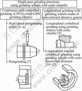
Fig. 1 Single-pass grinding processes carried out using grinding wheels with conic chamfer [1-7, 9-11]
The angle of the conic chamfer �� and its breadth bc are selected depending on machining allowance ae, total grinding wheel height T and the quality requirements of the machined objects. As the height T increases, the conic zone grows and the c angle decreases. It can assume really low values, e.g. for ae = 0.20 mm, T = 20 mm, bc = 12 mm, and c = 0.95��. Thus, an extremely important issue is the possibility of precise shaping of the conic chamfer, using special instrumentation.
Table 1 An example of grinding wheel with zone-diversified structure with conic chamfer used in a single-pass internal cylindrical grinding process [12-14]

3 Microdiscontinuities of grinding wheel active surface
Microdiscontinuities of the GWAS introduce local discontinuities into the surface structure of the tool and do not interfere with its macro-geometry. They are usually shaped as grooves and pits spread out in a regular manner. Their specific configurations are obtained with the use of the dressing operations, as presented schematically in Fig. 2 [8].
Application of microdiscontinuities on the grinding wheel active surface improves its wear properties. It influences the spread of heat and mechanical energy in the cutting zone positively, also allowing for better removal of excess heat and chips from the grinding zone and improving the effectiveness of the coolant liquid feed [8]. These properties prolong the service life of the grinding wheel, as well as supporting the course and effects of the grinding process. The different cutting and wear properties of the grinding tool can also be obtained, depending on the required technical conditions. This is achieved by adjusting the shape, dimensions, surface configuration and the relative participation of the microdiscontinuities on the GWAS. Microdiscontinuities can also be shaped on the GWAS in such a way that after their mapping on the machined surface, they will influence the condition of its wear properties in a positive manner. This aims at decreasing friction, absorption of dirt, additional development of the surface to improve adhesion of the protective layers, or enhancing the decorative effects.
The creation of microdiscontinuities of varying shape, and spatial lay-out on the GWAS depends on the local removal of the grinding wheel material using a single-grain dresser (Figs. 2(a)�C(d)) or dressing wheel (Figs. 2(e)�C(f)). This cut is realized directly after the process of dressing the grinding wheel and does not interfere with the shape of its macrogeometry [8].
4 Design of dressing device
The device was designed for the purpose of shaping the geometry of small-scale grinding wheels, used in internal cylindrical grinding processes. Shaping of the GWAS during the dressing operation was divided into three cuts, in which the following elements are shaped: the cylindrical surface, the conic chamfer and microdiscontinuities. The most difficult cut is the precise shaping of the conic chamfer with small angle c, and this is why a stiff slide plate and a micrometer screw were used for angular displacement of the plate. Also a large space between the axis of rotation and the point of contact of the spherical tip of the micrometer screw (a = 180 mm) was provided. In effect, the applied scope of the chamfer angle variability c = 0�C1.5�� was obtained by moving the end of the micrometer screw by 4.71 mm.
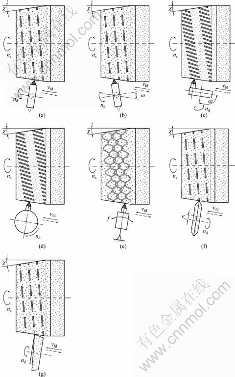
Fig. 2 Methods of shaping of micro-discontinuities on GWAS: (a)-(e) Using single-grain dresser; (f)-(g) Using dressing wheel [8]
4.1 Precision of shaping of conic chamfer
The schematic diagram of the setup for the setting of angular deflection applied in the designed device is presented in Fig. 3.

Fig. 3 Schematic diagram of setup for angle deflection
In the construction solution used, c angle is determined using the indirect method through direct measurement of a and b distances (Fig. 3):
 (1)
(1)
where a is the distance between the axis of rotation and the point of contact of the spherical tip of the micrometer screw with a mobile upper base of the device; b is the distance of dislocation of the tip of the micrometer screw.
In measurements using the indirect method, the systematic measurement result error depends on [14]:
1) Systematic size errors measured directly;
2) Correlations determining the relationship between the size measured in an indirect way and size measured in a direct way.
If size Y (measured indirectly) is connected with independent X1, X2, ��, XN (sizes measured in a direct way) with the following equation:
Y=F(X1, X2, ��, XN) (2)
then the systematic error is calculated using the equation which determines the measurement error with the exact differential method:
 (3)
(3)
where DX1, DX2, ��, DXN are systematic errors of the indirect measurement of sizes DX1, DX2, ��, DXN.
In the discussed case, equation (3) therefore takes the following form:
 (4)
(4)
In order to eliminate the influence of marks of particular components of equation (4), they were written in the following form:
 (5)
(5)
Next, the derivative  was calculated:
 (6)
(6)
where:
 (7)
(7)
Thus:
 (8)
(8)
Then, the subsequent derivative  was calculated in an analogical way:
 (9)
(9)
After the introduction of the results from the calculations of equations (8) and (9), equation (5) takes the following form:
 (10)
(10)
In the next step, errors Da and Db1 were determined, which resulted from the dislocation of the contact point of the micrometer screw, with spherical tip, from the mobile upper base of the device, as presented in Fig. 4.

Fig. 4 Diagram depicting point of contact of spherical tip of micrometer screw with movable upper base of device (r �C rounding radius of tip of micrometer screw)
Values of errors Da and Db1 were calculated knowing the distance a = 180 mm and the end fillet radius r = 4 mm, as well as assuming the maximum value of angular deflection of the upper basis of the device, which is 1.5��:
 (11)
(11)
Error Db1 was calculated using the equation for the arc arrow of the circular segment:
 (12)
(12)
In the discussed case, h = Db1 and a = 2Da, thus:
 =��0.001 4 mm (13)
The distance of dislocation of the tip of the micrometer screw b for angle c = 1.5�� is
 =180��0.026 2=4.713 5 mm (14)
While error Db, according to the principle of addition of systematic errors [14], is equal to the sum of the above calculated component Db1 (11) and the limiting acceptable error reading of the applied micrometer with the range of 50-75 mm, which is Db2= ��0.005 mm. Thus:
 =0.001 4+0.005=��0.006 4 mm (15)
Finally, after substitution of data and calculation of equation (8), the following value of the systematic error of angle setting in the device designed (for the maximum value from the used range of conic chamfer angle variability c = 1.5��) is

 (16)
(16)
Thus: D�� = ��5.059 1��10-5��.
The low value of the calculated Dc error results from the limited range of conic chamfer angle variability and the construction of the device (large distance a from the axis of rotation to the point of contact of the micrometer screw).
4.2 Setup with horizontal axis of spindle
In the first construction variant, the direct current motor YDK YA-010 produced by Yamamoto Electric Corp. (Japan), powering the disc with single-grain diamond dresser, was mounted horizontally (axis of rotation was parallel to the base). Figures 5 and 6 present a 3D model of the device in such a setup.
The main working motions are made by the disc, rotating with nd speed, to which the dresser was mounted. The mounting disc was equipped with two seatings allowing for mounting the dresser on its perimeter and anterior. This allows shaping of the microdiscontinuities according to the kinematics presented in Figs. 2(a)-(c). Moreover, the disc was equipped with blockades facilitating its immobilization in the right position, which is necessary when the conic chamfer is shaped.
The motor was mounted to the slide plate using the turntable with horizontal motor handle, which makes rotation of the motor axis in the basis plane, by degree w = 0-90��, possible. This further expands the functionality of the device and enables to shape microdiscontinuities in the kinematics presented in Figs. 2(b)-(c).

Fig. 5 Front view of 3D model of device for precision shaping of grinding wheel macro- and micro-geometry �C Setup with horizontal axis of spindle [15]

Fig. 6 Rear view of 3D model of device for precision shaping of grinding wheel macro- and micro-geometry �C Setup with horizontal axis of spindle [15]
The slide plate is set into reciprocating motion with speed vfd by the power transmission system. The most important element of the power transmission system is the driving motor with worm gear, which transmits the power through the toothed rack to the plate. Limit switches were installed in extreme positions on the slide plate, which, along with the contractor, allows for a change of direction in the rotation of the driving motor and thus changes in the direction of the slide plate motion. Moreover, the device was equipped with the slide plate blockade, which allows shaping the cylindrical zone of the GWAS, using the axial table feed of the grinding machine. The slide plate was mounted in a rotational upper base whose rotation angle is regulated using the micrometer screw mounted to the bottom base.
All of the elements of the device were mounted on a backing plate, which allowed the device to be mounted to the work table of the grinding machine.
The prototype of the device, prepared in accordance with the above-described project, was mounted in the workspace of the universal grinding machine RUP 28P (Fig. 7) equipped in electrospindle FISCHER type EV?70/70-2WB (maximum rotation speed 60 000 r/min, power of machine cutting 5.2 kW), as presented in Fig. 7.
In Figs. 8 and 9, the completed device was presented in a few variant working setups.

Fig. 7 Experimental setup: 1��Universal grinding machine RUP 28P; 2��Grinding wheel electrospindle FISHER EV-70/70-2WB; 3��Dosage system of air-oil mixture IG 54-2; 4��Frequency converter SIEB&MEYER 21.60; 5��Cooling unit IK?V07; 6��Computer with control program; 7�� Frequency converter SJ100 controlling direct current motor of workpiece spindle; 8��Workpiece spindle; 9��Device for precision shaping of grinding wheel geometry

Fig. 8 Prototypes of device for precision shaping of grinding wheel macro- and micro-geometry: (a) Dresser turntable rotation angle w = 90��; (b) Dresser turntable rotation angle w = 0��

Fig. 9 Prototypes of device for precision shaping of grinding wheel macro- and micro-geometry equipped with CBN dressing plate: (a) Overall view; (b) Mounting disc with holder of CBN dressing plate
Figure 8(a) presents the device with the turntable set at the degree w = 90��, with blocked rotational movement on the mounting disc of the dresser and with slide plate motion. Such a setup enabled the first cut of the GWAS shaping operation to be performed, and this consisted in dressing the cylindrical zone of the grinding wheel, using the grinding machine table feed.
Next, the GWAS conic chamfer was shaped. This was possible when the blockade was released and the slide plate reciprocating motion started. The conic chamfer angle value was set using the micrometric screw, while the slide plate feed speed vfd was regulated using the driving motor feeder.
The last cut shaped the GWAS microdiscontinuities, which could be carried out in a configuration corresponding to Fig. 2(c), as illustrated in Fig. 8(b). For this purpose, the blockade of the rotation of the dresser mounting disc must be released and the right kinematic parameters must be set to obtain the demanded effect. Figure 8 presents the device equipped with a single-grain diamond dresser with mass Qd = 1.25 kg. The micro- discontinuities can also be shaped using the cutting slates, such as those presented in Fig. 9 made from CBN. The device settings, as shown in Fig. 9, enabled the acquisition of microdiscontinuities compatible with the kinematics presented in Fig. 2(a).
Figure 10 presents a macrophotography (Fig. 10(a)) and SEM microphotography (Fig. 10(b)) of the finished grinding wheel with conic chamfer with angle c = 1.50�� and breadth b = 12.6 mm, as well as microdiscontinuities shaped using the described device.
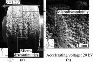
Fig. 10 Macrophotography (a) and SEM microphotography (b) of GWAS with conic chamfer and microdiscontinuities shaped using designed device (SEM microphotography obtained by JEOL JSM-5500LV scanning electron microscope produced by JEOL Ltd.)
In all of the above described cuts shaping the macro- and micro-discontinuities of the GWAS, the dressing depth was regulated using the feed-in system of the grinding wheel.
4.3 Setup with vertical axis of spindle
A construction solution allowing for shaping microdiscontinuities in the setup presented in Fig. 2(d) was also designed. For this purpose, the motor handle construction was changed in a way which facilitated its mounting both vertically and horizontally. The developed solution is presented in Figs. 11 and 12.
Such modifications of the construction allowed for shaping of the GWAS microdiscontinuities in four kinematic variants presented in Figs. 2(a)-(d). Due to this, as well as the possibility of shaping cylindrical surfaces and the precision performance of the conic chamfer, a universal device with great functionality was obtained.
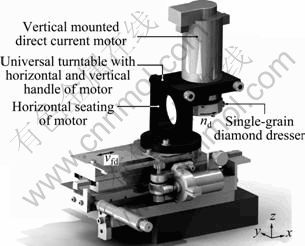
Fig. 11 Anterior view of 3D model of device for precision shaping of grinding wheel macro- and micro-geometry �C setup with vertical axis of spindle

Fig. 12 Posterior view of 3D model of device for precision shaping of grinding wheel macro- and micro-geometry �C Setup with vertical axis of spindle
4.4 Results of experimental verification of precision of conic chamfer shaping
The determined systematic error value Dc was compared with the results of the applied and obtained conic chamfer angles shaped, using the developed device, upon the GWAS.
The measurement of accuracy for the shaping of the conic chamfer angle of the GWAS was carried out by bench-type coordinate measuring machine Video- Check?-IP 250, produced by Werth Messtechnik GmbH (Germany). A general view of this machine is presented in Fig. 13.
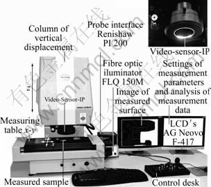
Fig. 13 General view of bench-type multisensor coordinate measuring machine Video-Check? -IP 250, produced by Werth Messtechnik GmbH
The Video-Check?-IP 250 was equipped with vision head, the main element of which was a high-resolution CCD camera. Images from the camera were processed to detect the contours of the measured object in incident and transmitted light. In this configuration, the machine is generally used for non-contact 2D and 3D measurements of a wide range of machine parts, machining tools as well as optic and electronic components. The Video-Check?-IP 250 used in measurements is characterized by the following features: measuring range: 250 mm (x-axis), 125 mm (y-axis), 200 mm (z-axis), resolution 0.1 ��m; range of magnifications: stepped (9 selective degrees) from 50 to 150. All measurements were carried out in automatic mode. In this case, a special measuring program was used, prepared in WinWerth? 6.21 software.
In order to check the precision of the designed device, six macrogeometries of the GWAS with conic chamfers of angle values c = 0.00��, 0.38��, 0.57��, 0.86��, 1.15�� and 1.50��, and with constant conic chamfer breadth bc=10 mm were shaped, as presented schematically in Fig. 14.

Fig. 14 Parameters of conic chamfers made for estimating precision of designed device
Extreme values and four exemplary ones, from the applied variability range of 0-1.5��, were shaped. The angle between the approximated lines, along with the 16 points of the cylindrical zone of the grinding wheel and the 16 points of the conic zone, were measured. Each measurement was repeated five times. A grinding wheel with the following technical specifications was used in the experimental investigation: 1?35��20��10?SG/ F60 K7VDG. This grinding wheel was devoid of zone-diversified structure and had SG size 60 grains throughout the whole volume. Such a grinding wheel did not introduce measurement errors resulting from different outlines, of the zones with varying structure.
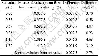
The average results, obtained from five measurements for each c angle value with determined deviations from the set value are presented in Table 2.
The average Dc error determined on the basis of the measurement of the geometry of the GWAS was ��2.73��10-2 ��. This value is then three orders higher than the systematic error of the device for shaping the conic
Table 2 Average results of measurements of angles of conic chamfers of GWAS chamfer of grinding wheels calculated earlier (��5.06��10-5 ��). The increase of the error results is due to the characteristics of the research stand, which, apart from lack of precision of the device itself, also suffered from the following factors, and all of these influenced the acquired geometry of the grinding wheel:
1) The mistake of parallel setting the dresser towards the grinding wheel spindle in the base position (0?);
2) Run-out caused by the error of coaxial mounting of the grinding wheel in the spindle;
3) Elastic deformation and vibrations of the dresser-grinding wheel system occurring during shaping of the GWAS.
Moreover, the angle values were measured from the grinding wheel surface with the error of the straight lines approximation on the basis of the 16 points registered upon the irregular profile of the grinding wheel.
5 Conclusions
1) The described dressing device construction allows for precise shaping of macro- and microgeometry of the active surfaces of the grinding wheels, required in the single-pass internal cylindrical grinding process.
2) This device allows the shaping of cylindrical surfaces, conic chamfer with low angular values c = 0-1.5��, as well as the GWAS microdiscontinuities in a few kinematic variants.
3) As a result of the performed theoretical and experimental analysis, it is determined that the error of shaping the conic chamfer angle within the range of c = 0-1.5?, using the developed device, is approximately ��3%. This value translates into an error of approximately ��0.03?, which corresponds to obtaining the required value of grinding depth ae with precision ��0.007 9 mm and chamfer breadth bc with error ��0.3 mm (maximum values for c = 1.5?).
4) Prototype tests confirm the assumed functionality of the device, which allows for shaping of the microdiscontinuities on the GWAS in the kinematic setup. Application of the modified engine handle facilitates shaping of the microdiscontinuities in the setup.
5) The described device significantly speeds up the shaping of the GWAS with unconventional macro- and micro-geometry. Such a device can be used mostly in experimental investigations on the influence of this type of geometry of the grinding wheel on various grinding processes.
6) Industrial applications include single-pass grinding processes, as well as those in which it is necessary to obtain a typical cutting and operating properties of the grinding wheel, e.g., grinding of hard-to-cut materials.
Acknowledgement
Part of this work was supported by the Polish Ministry of Science and Higher Education under Grant No. N503 214837.
The Authors wish to thank Mr. Andrzej Nowicki from Laboratory Team I for his help during experimental investigations of the dressing process, Mr. Krzysztof Maciejewski from the Laboratory of Metrology and Measurement Systems for optical measurements carried out by coordinate measuring machine Video-Check?-IP 250, Mr. Ryszard Gritzman from Central Laboratory of Institute of Mechatronics, Nanotechnology and Vacuum Technique for acquisition of SEM micrographs as well as Mr. Daniel Wilczy��ski, MSc, BSc, for his help in a modified version of the device for precision shaping of the grinding wheel geometry.
Nomenclature
ae��Machining allowance, mm
bc��Conic chamfer breadth, mm
D��Grinding wheel outside diameter, mm
e��Eccentric value, mm
f��Dresser oscillation frequency, Hz
H��Inside diameter of grinding wheel, mm
nd��Dresser rotational frequency, r/min
ns��Grinding wheel rotational frequency, r/min
Qd��Mass of diamond dresser, kg
r��Rounding radius of tip of micrometer screw, mm
T��Grinding wheel total height in axial direction, mm
T1��Height of rough grinding zone, mm
T2��Height of finish grinding zone, mm
vfa��Axial table feed speed, mm/s
vfd��Dresser table feed speed, mm/s
c��Conic chamfer angle, (��)
w��Dresser turntable rotation angle, (��)
References
[1] MARINESCU I D, HITCHINER M, UHLMANN E, ROWE W B, INASAKI I. Handbook of machining with grinding wheels [M]. Boca Raton: CRC Press, 2007.
[2] ROWE W B. Principles of modern grinding technology [M]. Burlington: William Andrew, 2009.
[3] JACKSON M J, DAVIM J P. Machining with abrasives [M]. New York: Springer, 2010.
[4] KLOCKE F. Manufacturing processes 2: Grinding, honing, lapping [M]. Berlin: Springler-Verlag, 2009.
[5] L?ETJENS P, MUSHARDT H. Grinding out hardened parts [J]. American Mechanist, 2004, 148(3): 52-59.
[6] WEBSTER J, TRICARD M. Innovations in abrasive products for precision grinding [J]. Annals of the CIRP, 2004, 53(2): 597-617.
[7] WEINERT K, FINKE M, K?TTER D. Wirtschaftliche alternative zum hartdrehen. innenrund-sch?lschleifen steigert flexibilit?t beim schleifen von futterteilen [J]. Maschinenmarkt, 2003, 109(48): 44-47.
[8] PLICHTA J, BILL T. Method of grinding wheel dressing using single-grain dresser: Polish, 155182[P]. 1992.
[9] S?OWI?SKI B, NADOLNY K. Effective manufacturing method for automated diameter grinding [J]. Journal of Advanced Mechanical Design, Systems, and Manufacturing, 2007, 1(4): 472-480.
[10] NADOLNY K, PLICHTA J. Possibilities of development in the single-pass internal cylindrical grinding [C]// Proceedings of the 19th Int Conference on Systems Engineering. Las Vegas: University of Nevada, 2008: 230-235.
[11] NADOLNY K, S?OWI?SKI B. Potential for increasing the effectiveness of automated production systems due to application of single-pass grinding [J]. Advances in Manufacturing Science and Technology, 2010, 34(2): 19-30.
[12] HERMAN D, PLICHTA J, NADOLNY K. Ceramic abrasive tool for single-pass cylindrical grinding and its manufacture: Polish Patent 204902[P]. 2009.
[13] HERMAN D, PLICHTA J, NADOLNY K. New ceramic abrasive tools for rough and finishing grinding in one pass [J]. Materials Science Forum, 2006, 526: 163-168.
[14] PLACKO D. Metrology in industry: The key for quality [R]. London: ISTE Ltd., 2006.
[15] NADOLNY K. Device for shaping of conic chamfer on grinding wheels surface for small angular values: Polish Patent 388765[P]. 2009.
(Edited by YANG Bing)
Received date: 2011-05-24; Accepted date: 2011-06-27
Corresponding author: Krzysztof NADOLNY, Assistant Professor, PhD; Tel: +48-94-3478412; E-mail: krzysztof.nadolny@tu.koszalin.pl

