Performance of viscous fluid dampers coupling adjacent inelastic structures under near-fault earthquakes
来源期刊:中南大学学报(英文版)2010年第6期
论文作者:阁东东 朱宏平 张俊兵 陈晓强
文章页码:1336 - 1343
Key words:nonlinear viscous fluid; damper; adjacent structure; near-fault earthquake; seismic response
Abstract: The behavior of viscous fluid damper applied in coupling structures subjected to near-fault earthquake was studied. The structural nonlinearity was characterized by Bouc-Wen model and several near-fault ground motions were simulated by the combination of a recorded earthquake (background ground motion) with equivalent velocity pulses that possess near-fault features. Extensive parametric studies were carried out to find the appropriate damping coefficient. Performances of viscous fluid dampers were demonstrated by the relationship between the force and displacement, the maximal damper force and stroke. The control performances were demonstrated in terms of the response reductions of adjacent structures. The results show that the dynamic responses of adjacent structures are mitigated greatly. Proper damping coefficients of connecting fluid dampers have a small difference, while adjacent structures under different near-fault ground motions with the same peak acceleration. The maximum force of damper is about 0.8 MN, and the maximum damper stroke is about ±550 mm. Satisfied viscous fluid dampers can be produced according to the current manufacturing skills.
J. Cent. South Univ. Technol. (2010) 17: 1336-1343
DOI: 10.1007/s11771-010-0639-5![]()
GE Dong-dong(阁东东)1, 2, ZHU Hong-ping(朱宏平)1, 2,
ZHANG Jun-bing(张俊兵)1, 2, CHEN Xiao-qiang(陈晓强)1, 2
1. School of Civil Engineering and Mechanics, Huazhong University of Science and Technology,
Wuhan 430074, China;
2. Hubei Provincial Key Laboratory of Control Structure, Huazhong University of Science and Technology,
Wuhan 430074, China
? Central South University Press and Springer-Verlag Berlin Heidelberg 2010
Abstract: The behavior of viscous fluid damper applied in coupling structures subjected to near-fault earthquake was studied. The structural nonlinearity was characterized by Bouc-Wen model and several near-fault ground motions were simulated by the combination of a recorded earthquake (background ground motion) with equivalent velocity pulses that possess near-fault features. Extensive parametric studies were carried out to find the appropriate damping coefficient. Performances of viscous fluid dampers were demonstrated by the relationship between the force and displacement, the maximal damper force and stroke. The control performances were demonstrated in terms of the response reductions of adjacent structures. The results show that the dynamic responses of adjacent structures are mitigated greatly. Proper damping coefficients of connecting fluid dampers have a small difference, while adjacent structures under different near-fault ground motions with the same peak acceleration. The maximum force of damper is about 0.8 MN, and the maximum damper stroke is about ±550 mm. Satisfied viscous fluid dampers can be produced according to the current manufacturing skills.
Key words: nonlinear viscous fluid; damper; adjacent structure; near-fault earthquake; seismic response
1 Introduction
In modern cities, increasing population but limited land lead to inadequate separation, often resulting in collision of adjacent structures during a strong earthquake. Pounding between adjacent structures was observed during most major urban earthquakes, such as Loma Prieta earthquake in 1989, Northridge earthquake in 1994, Kobe earthquake in 1995, and Turkey earthquake in 1999. Connecting two adjacent structures with various types of control devices which are passively, semi-actively or actively controlled, was proved to be a effective approach to prevent pounding and reduce the response of adjacent structures under earthquake excitation.
ZHANG and XU [1-2] obtained the optimal parameters of Kelvin model defined viscoelastic dampers and Maxwell model defined fluid dampers for achieving the maximum seismic response reduction of adjacent structures through both parametric and sensitivity studies. XU et al [3] performed an experimental study of adjacent structures connected by fluid dampers using two three-story building models and a linear viscous damper. YANG et al [4] carried out a comprehensive experimental investigation on the dynamic characteristic and seismic response of adjacent structures linked by fluid dampers. NI et al [5] developed a method for analyzing the random seismic response of a structural system consisting of two adjacent structures interconnected by non-linear hysteretic damping devices. BASILI and ANGELIS [6] studied the optimal passive control of adjacent structures interconnected by nonlinear hysteretic devices. The dynamic behavior of two adjacent structures connected with friction damper under harmonic ground excitation and various earthquake excitations was investigated by BHASKARARAO and JANGID [7].
Viscous fluid damper is a passive energy dissipation device that is commonly applied to civil structures to reduce structural vibrations induced by earthquake or
wind [8]. Compared with other types of energy dissipate devices, viscous fluid damper has several inherent and significant advantages: insensitivity to temperature change; small size in comparison to output force; easy installation; reliability and longevity; and almost free maintenance [8-10].
Numerous experimental and analytical studies show that viscous fluid dampers effectively mitigate the seismic response of linked adjacent structures [1-4]. However, in these investigations, the viscous fluid dampers were all modeled as Kelvin or Maxwell model, which are used to capture the linear behavior of viscous fluid dampers. The addition of dampers to the adjacent structures allowed the main structural elements to remain in their elastic range, and the earthquake excitations are limited to far field ground motions with low peak accelerations. Moreover, the researchers just concerned about the control effectiveness of the damper, but neglected the behavior of the damper itself, such as the maximal damper force and damper stroke, which are the important parameters of viscous fluid dampers. Linear viscous fluid dampers may develop excessive damper forces in applications where large structural velocities can occur, especially in long period structures subjected to intense ground motion [11]. The near-fault strong ground velocity time histories have large, brief pulses of ground motion that are potentially damaging to multi- story buildings. The near-fault pulse-like ground motion has large long-duration velocity and displacement pulse, and large peak ground acceleration especially in the fault-normal direction [12]. As mentioned above, pounding between adjacent structures is observed during most near-fault earthquakes. Owing to large displacements, structural systems exhibit nonlinearity. So, the performance of the nonlinear viscous fluid dampers in the adjacent inelastic structures subjected to near-fault ground motions is an important research topic.
The design of fluid viscous dampers is strongly affected by their force-deformation behavior and dynamic characteristics of the adjacent structures. The nonlinearity introduced in the dampers may lead to a poor building performance and important structural damage. In this work, seismic response analysis of adjacent structures connected by nonlinear viscous fluid dampers was presented. The effectiveness of nonlinear viscous fluid dampers was investigated in terms of the structural responses. The performances of nonlinear pure viscous fluid dampers were investigated based on the hysteresis loops and maximal damper forces.
2 Modeling of adjacent structures
2.1 Equation of motion
The two adjacent structures are assumed to be symmetric with their symmetric planes in alignment. The ground motion is assumed to occur in one direction in the symmetric planes of the buildings so that the problem can be simplified as a one-dimensional problem as shown in Fig.1 schematically. The floors of each building are at the same level. Both structures are assumed to be subjected to the same ground acceleration. Taking no account of the optimal displacement of dampers, uniform distribution of dampers in all stories of a structure is the most effective distribution from the point of view of response reduction.
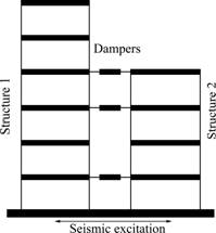
Fig.1 Adjacent structures connected by dampers
Fig.1 illustrates a structural system consisting of two adjacent high-rise structures of n1 and n2 (n1≥n2) stories, connected by viscous fluid dampers at some stories. The equation of motion of the coupled structural system subjected to seismic excitation can be expressed as
![]() (1)
(1)
where m, ke, kh and c are the n×n (n=n1+n2) mass, elastic stiffness, hysteretic stiffness, and internal damping matrices of the adjacent structures, respectively; x(t) is the n-dimensional story drift vector; the contribution of the force caused by a single damper fvdj is considered through the influence vector dj; and nd is the number of possible locations for a damper in the structure and equal to the minimum of n1 and n2; z(t) is the inter-story hysteretic displacement vector; m0 is the load indicating vector; and ![]() is the acceleration of ground motion.
is the acceleration of ground motion.
Many civil structures exhibit hysteresis characteristic when they are subjected to severe earthquakes. Bouc-Wen model can capture many commonly observed types of hysteretic behavior [13- 14]. The Bouc-Wen model typically consists of an output equation and a nonlinear first-order differential equation:
![]() (2)
(2)
![]() (3)
(3)
where subscripts j and i (i=1, 2) denote the jth floor of structure i; Fji is the inter-story restoring force; aji is an index represented the ratio of post-to-pre-yielding stiffness; zji is the inter-story hysteretic displacement; xji is the story drift; Aji, bji and gji are the parameters controlling the shape of the generated hysteresis loops; and hji determines the rate of transition from the elastic to yield state.
2.2 Calculation model of viscous fluid damper
A viscous fluid damper generally consists of a piston within a damper housing filled with a compound of silicone or similar type of oil [9, 15]. A viscous fluid damper dissipates energy by forcing a fluid to flow through orifices, causing a pressure difference and thereby force, which can be expressed as
![]() (4)
(4)
where subscript j denotes the jth damper; Cj is the damping coefficient determined mainly by the damper diameter and the orifice area; sgn( ) is the signum function; ![]() is the relative velocity between the two ends of the damper; and aj is the damper exponent ranging from 0.2 to 1 for seismic applications [15-17]. The damper exponent of viscous fluid damper was selected as 0.4 in this work.
is the relative velocity between the two ends of the damper; and aj is the damper exponent ranging from 0.2 to 1 for seismic applications [15-17]. The damper exponent of viscous fluid damper was selected as 0.4 in this work.
3 Dynamic analysis of structure-damper system
3.1 Ordinary differential equation (ODE) method
The numerical integration of Eqs.(1)-(4) can be done using a state-space formulation. By using the state-space representation, Eq.(1) can be written in the form

 (5)
(5)
In fact, Eq.(5) is a first-order differential equation, which describes a time-invariant control system. Once in this form, the equation can be conveniently solved using efficient solvers. In this work, the ODE solver from the MATLAB package is implemented for the numerical integration of Eq.(5).
3.2 Index of control effectiveness
The following linear quadratic performance index is usually chosen in structural vibration control under seismic excitation
![]() (6)
(6)
where tf is the duration time of ground motion. In fact, Eq.(6) represents the total kinetic energy in the adjacent structures. The aim of the coupled building control strategies is to reduce the motion of adjacent structures as much as possible. This objective can be achieved by minimizing the sum of the kinetic energy of the coupled structures at whole time steps during seismic excitations.
4 Near-fault ground motions
Due to complex rupture mechanism and limited quantity of available near-fault ground motions, it is difficult to comprehensively investigate the effect of pulse parameters of near-fault ground motion on the response of the coupled adjacent structures. The frequency component of equivalent velocity pulse is unitary, however, the real near-fault pulse-like ground motions contain abundant frequency components. To effectively simulate the fault-normal and fault-parallel components of near-fault ground motion, artificial near-fault ground motion can be generated through the superposition of a recorded ground motion with simple pulses that portray near-fault features. The reasonable model of equivalent velocity pulse was proposed by PARK et al [12]. The pulse effect of near-fault and the local characteristics of ground soil were taken into account in this model. According to synthesis method of manual simulation about the near-fault pulse-like ground motions, time history of velocity for artificial near-fault ground motion ![]() can be expressed as
can be expressed as
![]() (7)
(7)
where ![]() is the time history of velocity for normal ground motion, which is selected as background ground motion; the peak velocity of equivalent velocity pulse
is the time history of velocity for normal ground motion, which is selected as background ground motion; the peak velocity of equivalent velocity pulse ![]() is equal to that of the background ground motion
is equal to that of the background ground motion ![]() ; a is the participation coefficient of equivalent velocity pulse for the artificial near-fault ground motion
; a is the participation coefficient of equivalent velocity pulse for the artificial near-fault ground motion ![]() ; for instance, a (selected as 1, 2, and 4) indicates that the contribution rates of equivalent velocity pulse
; for instance, a (selected as 1, 2, and 4) indicates that the contribution rates of equivalent velocity pulse ![]() on artificial near-fault ground motion
on artificial near-fault ground motion ![]() reach 50.0%, 66.7% and 80.0%. The larger the a, the more significant the pulse effect [18-19]. During the synthetic process, adjustment about the velocity peak of
reach 50.0%, 66.7% and 80.0%. The larger the a, the more significant the pulse effect [18-19]. During the synthetic process, adjustment about the velocity peak of ![]() to coincide with that of
to coincide with that of ![]() is necessary. Then, the time history of velocity is differentiated to yield the time history of acceleration.
is necessary. Then, the time history of velocity is differentiated to yield the time history of acceleration.
The velocity pulse period, Tp, of the simulated near-fault ground motions is expressed by the moment magnitude (Mw) as follows [18-19]:
![]() (8)
(8)
Several models are available in the literatures for the simulation of near-fault ground motions. The analytical models summarized in Ref.[20] are composed of different piecewise functions or modulating functions to simulate near-fault ground motions with various velocity pulse characteristics. The analytical model used in Ref.[21] is represented by a single function, which is essentially an amplitude modulated sinusoid. The simplified model neglects the beginning time of the pulse and the integer parameter controlling the skewness of the pulse envelope. Moreover, this model simulates the velocity time history of near-fault ground motions with forward rupture directivity effect by a decaying sinusoid. Different impulse effects are achieved by adjusting a variable called the decay factor. The velocity- and acceleration-time histories of the ground motions are given by the following equations [18-19]:
![]() (9)
(9)
![]()
![]() (10)
(10)
where zp is the decaying factor of the sinusoid, which is similar to the damping factor in structural dynamics problems; wp is the frequency of the sinusoid; s is the initial amplitude of the velocity pulse; and t is the time.
The decaying sinusoids with zp =10%, 20% and 40% can simulate near-fault ground motions with multiple, forward- and backward and forward velocity pulses respectively, and increasing values of zp from 10% to 20% and to 40% results in only three, two and one significant pulse(s) respectively [19]. Thus, to simulate a near-fault ground motion with a peak ground velocity, vp, a pulse period, Tp, and a decaying factor, zp, the model parameters s and wp must be chosen such that the peak velocity and pulse period of the model match the given vp, and Tp respectively. For this purpose, first, wp is calculated as
![]() (11)
(11)
In Eq.(11), ![]() is introduced so that the velocity pulse period of the simulated near-fault ground motion matches the given vp when wp is substituted into Eq.(9). Next, the time, tp, at which the peak ground velocity occurs is calculated by setting Eq.(10) equal to zero and then solving for t
is introduced so that the velocity pulse period of the simulated near-fault ground motion matches the given vp when wp is substituted into Eq.(9). Next, the time, tp, at which the peak ground velocity occurs is calculated by setting Eq.(10) equal to zero and then solving for t
 (12)
(12)
Next, substituting tp into Eq.(9) and setting Eq.(9) equal to vp, s is calculated as
![]() (13)
(13)
Three earthquake records were selected as background motions in this work, which were Kobe earthquake in 1995, Duzce, Turkey earthquake in 1999 and Loma Prieta earthquake in 1989. The features of earthquake records used are listed in Table 1. In the table, PGA, PGV, and PGD represent the peak values of acceleration, velocity, and displacement of ground motion, respectively. At zp=10% and a=4.0, Fig.2 shows the three simulated near-fault ground motions, and the peak accelerations are scaled to 3 m/s2.
5 Numerical study
To illustrate the application of the coupled control strategies presented in this work for hysteretic structures, two 20-story high-rise structures having the same floor elevations with dampers connecting two neighboring floors were considered. The adjacent structures were modeled as hysteretic shear type structures having total height of 66 m with each story height of 3.3 m. The mass, shear stiffness, internal damping coefficient of structure 1 are uniform for each story with the mass of 1.29×10⁶ kg, the shear stiffness of 4.0×10⁹ N/m and the damping coefficient of 1.5×10⁶ N?s/m. For structure 2, the mass, shear stiffness and damping coefficient of each story are also identical with the same mass as structure 1 but with the shear stiffness of 2.5×10⁹ N/m and the damping coefficient of 1.0×10⁶ N?s/m only. It is assumed that the post- to pre-yield stiffness ratio α for each story is uniform and selected as 0.02. The nonlinear behavior of each story can be described by hysteretic model, with A=1.0, β=1.95, g=-0.75 and h=2.
Table 1 Important features of earthquake records used in this work

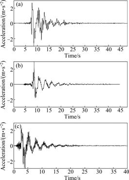
Fig.2 Simulated near-fault ground motions: (a) Kobe earthquake; (b) Turkey earthquake; (c) Loma Prieta earthquake
5.1 Parametric study
Parametric studies of the viscous fluid dampers were conducted to find appropriate damping coefficient in order to achieve the maximum seismic response reduction of the adjacent structures. Effects of damper coefficient on dynamic response mitigation of the 20-story adjacent structures are sought for different near fault earthquake records. Fig.3 shows the variations of displacement responses with damping coefficient for the first story drifts, while structures 1 and 2 are subjected to simulated near-fault ground motions derived from Kobe earthquake and itself. The variations of the kinetic energy with damping coefficient for structures 1 and 2 are displayed in Fig.4. From Figs.3-4, it can be observed that the optimal damping coefficient is about 7.0×10⁵ N?s/m for the purpose of minimizing the dynamic response of both adjacent structures. If the damping coefficient decreases or increases from 7.0×10⁵ N?s/m, the performance of damper will deteriorate gradually. Furthermore, for the adjacent structures subjected to various artificial near-fault ground motions that have different participation coefficients of equivalent velocity pulse, the appropriate damping coefficient of damper are just the same. Obviously, the larger the participation coefficients of equivalent velocity pulse, the more intensive the response mitigation of adjacent structures.
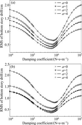
Fig.3 Variations of root mean square (RMS) of bottom story drift with damping coefficient for adjacent structures subjected to derived Kobe earthquake: (a) Structure 1; (b) Structure 2
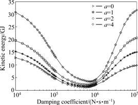
Fig.4 Variations of kinetic energy with damping coefficient of dampers for adjacent structures subjected to derived Kobe earthquake
Due to the installation of viscous fluid dampers, the total kinetic energy of adjacent structures are mitigated to the same level basically.
Figs.5-6 show the variations of total kinetic energy with damping coefficient for structures 1 and 2 under simulated near-fault ground motions derived from Turkey and Loma Prieta earthquakes, respectively. It can be identified that the beneficial damping coefficients are basically in accord with the results from the structures
excited by Kobe earthquake. Moreover, the dynamic response can be reduced to comparative level for structures under Turkey or Loma Prieta derived near- fault earthquakes, respectively, even if the participation coefficients of equivalent velocity pulses have significant difference. The proper damping coefficients of dampers show only a little difference for different near fault ground excitations, it would be very helpful for the application of viscous fluid damper in coupling structure control strategies.
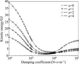
Fig.5 Variations of kinetic energy with damping coefficient for adjacent structures under derived Turkey earthquake
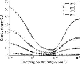
Fig.6 Variations of kinetic energy with damping coefficient for adjacent structures under derived Loma Prieta earthquake
5.2 Performance of viscous fluid damper
In this section, extensive time history response analysis was carried out to confirm the control performance of the viscous fluid dampers for example structures subjected to various near-fault ground motions. Fig.7 shows the response histories of bottom story drifts of bottom floor versus time, while the adjacent structures are excited by simulated near-fault earthquake with participation coefficient of 4.0 on the basis of Kobe earthquake. It can be observed that after installing the dampers, the bottom story drifts of structures 1 and 2 are reduced effectively.
Table 2 lists the control effectiveness of damper connected adjacent structures under various near resource earthquakes. The performance of viscous fluid damper is quantified by the percentage reduction of RMS values of the seismic responses about coupled adjacent structures with respect to the structures without control. In terms of the top floor displacements and accelerations, bottom story drifts and base restoring forces, the effectiveness of viscous fluid damper was investigated. Obviously, the seismic responses of adjacent structures are mitigated effectively.
The relationships between the displacement and force of damper at the top floor level while structures excited by derived Kobe, Turkey and Loma Prieta earthquakes are shown in Fig.8. It can be found from Fig.8(a) that the maximum force of damper is about 0.8 MN, and the maximum damper stroke is about ±550 mm, which can be achieved for viscous fluid damper but a large stroke is necessary obviously. The Taylor Devices’ seismic viscous fluid dampers are available in output levels of about 6 MN force, and the parameter is obtained through the website of Taylor Devices. The stroke of viscous fluid dampers applied in the bridge engineering can reach up to ±550 mm.
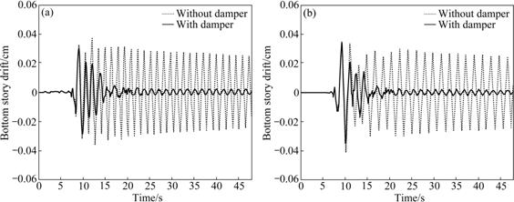
Fig.7 Response histories of bottom story drifts of adjacent structures under Kobe earthquake with participation coefficient of 4.0: (a) Structure 1; (b) Structure 2
Table 2 Percentage reduction of RMS of seismic responses about damper connected adjacent structures under various near resource earthquakes %
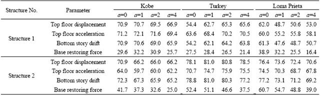
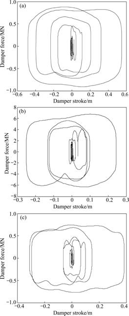
Fig.8 Hysteretic loops of damper at top floor level while adjacent structures are subjected to derived Kobe (a), Turekey (b) and Loma Prieta (c) earthquakes with a=4
6 Conclusions
(1) When adjacent structures are subjected to various near-fault earthquakes with peak acceleration scaled 3.0 m/s2, the proper damping coefficients of connecting damper basically have a small difference, even if the participation coefficients of equivalent velocity pulses reach 4.0. This will be very helpful for the application of viscous fluid dampers in coupling structure control strategies.
(2) The maximum force is about 0.8 MN and the maximal damper stroke is about ±550 mm for the connecting dampers while two structures are excited by derived Kobe earthquake. Viscous fluid dampers with large stroke can be produced by adopting proper manufacturing technique. Each story may be equipped with one or more dampers in practical engineering, and viscous fluid dampers may be installed only at several stories.
(3) Dynamic responses of two adjacent structures under near field ground motions are mitigated greatly due to the addition of connecting dampers.
References
[1] ZHANG Wen-shou, XU You-lin. Dynamic characteristics and seismic response of adjacent buildings linked by discrete dampers [J]. Earthquake Engineering and Structural Dynamics, 1999, 28: 1163-1185.
[2] ZHANG Wen-shou, XU You-lin. Vibration analysis of two building linked by Maxwell model-defined fluid dampers [J]. Journal of Sound and Vibration, 2000, 233(5): 775-796.
[3] XU You-lin, ZHANG Wen-shou, KO Jan-ming. Experimental investigation of adjacent buildings connected by fluid damper [J]. Earthquake Engineering and Structural Dynamics, 1999, 28: 601-631.
[4] YANG Zhen, XU You-lin, LU Xi-lin. Experimental seismic study of adjacent buildings with fluid dampers [J]. Journal of Structural Engineering, 2003, 129(2): 197-205.
[5] NI Yi-qing, KO Jan-ming, YING Zu-guang. Random seismic response analysis of adjacent buildings coupled with non-linear hysteretic dampers [J]. Journal of Sound and Vibration, 2001, 246(3): 403-417.
[6] BASILI M, ANGELIS M D. Optimal passive control of adjacent structures interconnected with nonlinear hysteretic devices [J]. Journal of Sound and Vibration, 2007, 301(1/2): 106-125.
[7] BHASKARARAO A V, JANGID R S. Seismic analysis of structures connected with friction dampers [J]. Engineering Structures, 2006, 28(5): 690-703.
[8] CONSTANTINOU M C, SYMANS M D. Experimental study of seismic response of buildings with supplemental fluid dampers [J]. Journal of Structure Design of Tall Buildings, 1993, 2(2): 93-132.
[9] LEE D, TAYLOR D P. Viscous damper development and future trends [J]. Journal of Structure Design of Tall Buildings, 2001, 10(5): 311-320.
[10] SONG Xu-ming, DAI Gong-lian, ZENG Qing-yuan. Seismic response analysis and control of self-anchored suspension bridge [J]. Journal of Central South University: Science and Technology, 2009, 40(4): 1079-1085. (in Chinese)
[11] MALHOTRA P K. Response of buildings to near-field pulse-like ground motions [J]. Earthquake engineering and Structure Dynamics, 1999, 28: 1309-1326.
[12] PARK S W, GHASEMI H, SHEN J, SOMERVILLE P G, WEN W P, YASHINSKY M. Simulation of the seismic performance of the Bolu Viaduct subjected to near-fault ground motions [J]. Earthquake Engineering and Structure Dynamics, 2004, 33: 1249-1270.
[13] WEN Y K. Method for random vibration of hysteretic systems [J]. Journal of the Engineering Mechanics Division, 1976, 102(2): 249- 263.
[14] ISMAIL M, IKHOUANE F, RODELLAR J. The hysteresis Bouc-Wen model: A survey [J]. Archives of Computational Methods in Engineering, 2009, 16(2): 161-188.
[15] LIN W H, CHOPRA A K. Understanding and predicting effects of supplemental viscous damping on seismic response of asymmetric one-storey systems [J]. Earthquake Engineering and Structural Dynamics, 2001, 30: 1475-1494.
[16] MARTINEZ-RODRIGO M, ROMERO M L. An optimum retrofit strategy for moment resisting frames with nonlinear viscous dampers for seismic applications [J]. Engineering Structures, 2003, 25: 913-925.
[17] GEOL R K. Seismic response of linear and non-linear asymmetric systems with non-linear fluid viscous dampers [J]. Earthquake Engineering Structure Dynamics, 2005, 34: 825-846.
[18] DICLELI M, BUDDARAM S. Equivalent linear analysis of seismic-isolated bridges subjected to near-fault ground motions with forward rupture directivity effect [J]. Engineering Structures, 2007, 29: 21-32.
[19] DICLELI M. Supplemental elastic stiffness to reduce isolator displacement for seismic-isolated bridges in near-fault zones [J]. Engineering Structures, 2007, 29: 763-775.
[20] MAVROEIDIS G P, PAPAGEORDIOU A S. A mathematical representation of near-fault ground motions [J]. Bulletin of Seismological Society of America, 2003, 93(3): 1099-1131.
[21] HE W L, AGRAWAL A K. Analytical model of ground motion pulses for the design and assessment of seismic protective systems [J]. Journal of Structural Engineering, 2008, 134(7): 1177-1188.
Foundation item: Project(50778077) supported by the National Natural Science Foundation of China; Project(50925828) supported by the National Science Foundation for Distinguished Young Scholars of China
Received date: 2010-02-01; Accepted date: 2010-05-08
Corresponding author: ZHU Hong-ping, PhD, Professor; Tel: +86-27-87542631; E-mail: hpzhu@mail.hust.edu.cn

