开洞对脱硫塔大型薄壁圆柱壳抗风稳定性的影响
王登峰1,曹平周2,王元清3,石永久3
(1. 江南大学 环境与土木工程学院,江苏 无锡,214122;
2. 河海大学 土木与交通学院,江苏 南京,210098;
3. 清华大学 土木工程系,北京,100084)
摘要:基于某脱硫塔大型薄壁圆柱钢壳为工程背景,采用非线性有限元方法系统地研究有圆形开洞的圆柱壳在风荷载作用下的屈曲模态和屈曲承载力,分析开洞位置、开洞尺寸对于柱壳抗风稳定性的影响。根据大量计算结果,划定开洞不利区域,并根据开洞对柱壳抗风稳定承载力的影响提出判断孔洞直径的标准。研究结果表明:进行开洞圆柱壳的抗风稳定性验算时,先要确定最不利的过风方向。在开洞不利区域内开大洞时,孔洞会使柱壳抗风稳定承载力明显降低,需要考虑开洞对柱壳抗风稳定性的影响。在壳体上开洞不利区域以外区域开洞,或者在开洞不利区内开小洞,开洞的影响较小,可不考虑其对柱壳抗风稳定性的影响。在开洞不利区域,随着开洞直径的增大,柱壳抗风稳定承载力降低。在壳体上开洞不利区以外区域开洞时,随着开洞直径的增大,柱壳抗风稳定承载力基本保持不变。
关键词:结构工程;薄壁圆柱壳稳定性;非线性有限元;开洞;风荷载
中图分类号:TU392.6 文献标志码:A 文章编号:1672-7207(2013)10-4228-10
Influence of cutout on buckling of large-scale thin-walled cylindrical shells of desulphurizing tower under wind loading
WANG Dengfeng1, CAO Pingzhou2, WANG Yuanqing3, SHI Yongjiu3
(1. School of Environment and Civil Engineering, Jiangnan University, Wuxi 214122, China;
2. School of Civil and Transportation Engineering, Hohai University, Nanjing 210098, China;
3. Department of Civil Engineering, Tsinghua University, Beijing 100084, China)
Abstract: Systematical investigations were conducted into the buckling mode and buckling capacity of the large-scale thin-walled cylindrical shells of a practical desulphurizing tower with circular cutout under wind loading by nonlinear finite element method. The influences of the cutout position and cutout size on the buckling behavior of cylindrical shells under wind loading were investigated. Based on a great many computation results, the unfavorable cutout region was delimited. The criterion for cutout size to judge whether the cutout is large or small was proposed on the basis of the influence of cutout on the buckling capacity. The results show that when checking the buckling capacity of cylinder with cutout against wind loading, it is supposed to firstly define the most unfavorable wind crossing direction. When the large cutout is situated in the unfavorable cutout region, it is necessary to take the influence of cutout into account for the check of wind resistance as the cutout will reduce the buckling capacity significantly. When the small cutout is situated in the unfavorable cutout region, or the cutout is situated out of such region no matter whether the cutout is large or small, it is unnecessary to take account of the influence of cutout for the check of wind buckling capacity. The buckling capacity under wind load decreases as the cutout size increases when the cutout is situated in the unfavorable cutout region. The buckling capacity approximately keeps constant as the cutout size increases when the cutout is situated out of the unfavorable cutout region.
Key words: structural engineering; buckling of thin-walled cylindrical shells; nonlinear finite element; cutout; wind load
脱硫塔是火电厂中用以减小大气污染的关键环保设备,其结构形式一般为大型薄壁圆柱钢壳,风荷载是其承受的主要横向荷载,风荷载作用导致柱壳丧失稳定性是主要破坏方式之一。在风荷载作用下可能使圆柱壳产生3种屈曲形式[1-3]。粗矮的圆柱壳在风压造成的环向压应力作用下发生类似于承受均匀外部径向压力时的屈曲,如图1(a)所示(图1中箭头表示过风方向)。中等高径比的圆柱壳,由于中上部截面的椭圆化,导致抵抗轴压刚度不足而发生屈曲,其屈曲特征为在迎风面的上部1/2区域产生水平向的波褶,如图1(b)所示。细高柱壳(高径比较大)在底部1/3区域的背风侧因轴向内力较大而发生屈曲,如图1(c)所示。Greiner等[4-5]研究了风荷载作用下圆柱壳稳定的缺陷敏感性。实际工程中的脱硫塔大型薄壁圆柱壳结构,经常需要在壳体上开众多较大的孔洞,如观察孔、检修孔、搅拌器开孔等。孔洞的存在影响了柱壳的刚度,改变了圆柱壳上应力和变形的分布状态,且在开洞区产生应力集中,引起稳定承载力的下降。Toda等[6-10]通过试验与数值计算等方法分别研究了开洞圆柱壳在轴压、纯弯、内压与轴压共同作用等荷载工况下的稳定性,结果表明小开洞对柱壳稳定性影响不大,大开洞会显著减小柱壳的稳定承载力。界定孔洞直径的临界值,与圆柱壳几何构造和荷载情况有关。风荷载引起的圆柱壳内力分布很不均匀,开洞对圆柱壳风荷载作用下稳定性的影响涉及因素较多,目前关于此课题的研究资料甚少。工程中有大量中等高径比的圆柱壳结构,本文作者基于1座实际的中等高径比脱硫塔几何构造,通过非线性有限元方法,研究开洞对此类薄壁圆柱壳风荷载作用下稳定性的影响。考虑脱硫塔上开洞大多为圆形,本文研究圆形的开洞情况。
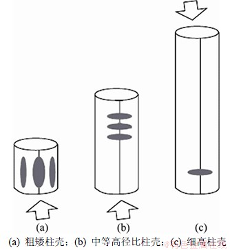
图1 风压下薄壁圆柱壳的屈曲形式
Fig. 1 Typical buckling modes of thin-walled cylindrical shells under wind loading
1 分析模型
1.1 结构模型
本文分析的背景脱硫塔圆柱壳高度H=30 m,半径R=8 m,壁厚t=16 mm,H/R=3.75,R/t=500,几何尺寸上属于中等高径比薄壁圆柱壳。结构的几何构造和位移坐标系如图2所示。采用有限元程序ANSYS进行分析。实际工程中的脱硫塔在底部塔壁钢板与钢底板通过焊缝连接,因此,塔底钢板对塔壁的转动约束作用较弱,塔壁在底部处可视作简支约束,在柱壳底部约束3个平动自由度。计算比较表明[11],在模型中的柱壳顶部设置1个长×宽×高为400 mm×400 mm×30 mm的箱形截面加劲肋可以近似等效地模拟实际结构中柱壳顶盖对壳体的约束作用,即2种模型的屈曲模态类似,屈曲承载力基本相等,且箱形加劲肋可以保证柱壳顶部截面在加载过程中保持在同一个平面上,不发生翘曲变形。为了提高建模效率,对圆柱壳顶部结构简化,用1个长×宽×高为400 mm×400 mm×30 mm的箱形截面加劲肋模拟实际结构中的顶盖。圆柱壳选用Shell181单元模拟,顶部加劲肋选用Beam188单元模拟。为了使研究结果对一类开洞薄壁圆柱壳在风荷载作用下的稳定性问题具有更普遍的参考意义,结构模型中忽略了背景脱硫塔由工艺要求决定的结构特点。由于薄壁圆柱壳在风荷载作用时失稳大多发生在弹性阶段[1, 4],对非细高的柱壳材料非线性的影响更小[4],所以,本文进行材料为弹性的几何非线性分析。钢材弹性模量E=2.06×10⁵ N/mm2,泊松比ν=0.3。用弧长法跟踪屈曲路径。当脱硫塔底部有石灰浆液时,内压使壳壁产生环向拉应力,可以部分抵消风荷载引起的环向压应力,对于抗风是有利的。本文仅研究柱壳内无浆液,即空壳时的风荷载作用下稳定性。
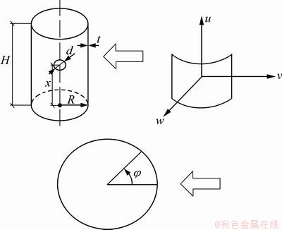
图2 开洞圆柱壳几何构造和位移坐标系
Fig. 2 Geometry of cylinder with circular cutout and displacement coordinate system
1.2 网格精度判定
网格划分精度是影响有限元计算结果是否准确的主要因素之一。本文采用完善柱壳的有限元分析结果与经典解对比的方法来判定网格精度合理性,即先对简支完善圆柱壳均匀轴压下的特征值屈曲承载力进行分析,通过其解与经典解Nx,cl比较,当误差不超过1%时,认为网格划分满足精度要求。均匀轴压下完善圆柱壳的线弹性屈曲承载力Nx,cl为[12]:
 (1)
(1)
本文分析时取网格轴向和环向尺寸为300 mm×1°,在开洞区域再进行网格细化,开洞上下各一倍线弹性弯曲半波长度λ0( )内,网格轴向尺寸取200 mm。非线性分析表明:开洞圆周的网格尺寸分别按60 mm/格和40 mm/格计算时,风压作用下屈曲模态相似,稳定承载力相差不超过2%,所以,开洞圆周网格尺寸取60 mm/格。
1.3 风荷载作用形式
径向风压的分布在柱壳表面是沿着环向和轴向变化的[13]。本文径向风压值pwind(φ)随环向变化的函数取傅里叶级数形式,如下式所示:
 (2)
(2)
式中:pr为迎风线上(φ=0°)的实际径向风压;cm为傅里叶系数,其取值按文献[4]确定,c0=-0.65,c1=0.37,c2=0.84,c3=0.54,c4=-0.03,c5=-0.07。
考虑到建造脱硫塔的火电厂一般建在建筑物密度不高的乡镇或城郊,因此,风压随着柱壳高度按照GB 50009―2001(《建筑结构荷载规范》)[14]中B类地区(指田野、乡村、丛林、丘陵以及房屋比较稀疏的乡镇和城市郊区)的风压高度系数线性变化。
1.4 有限元模型的对称性
考虑到风荷载关于迎风线对称,对于完善结构以及开洞在迎风线或者背风线上(φ=180°)的柱壳可以取一半结构建模,对称边界上施加对称边界条件。对于单个开洞在侧翼等不对称的情况,必须对整体结构建模。
1.5 分析方法验证
考虑圆柱壳承受风荷载作用下屈曲的风洞试验研究很少,且关于试验中风压分布函数及试件尺寸的数据资料不够完整,难以据此进行有限元模拟并将有限元计算与试验结果比较,本文将承受均匀径向外压下柱壳的特征值屈曲荷载与理论解进行对比,以验证本文方法分析柱壳承受径向压力时响应的可靠性。均匀径向外压下完善圆柱壳的环向屈曲应力σφ,cl经典解为[15]
 (3)
(3)
式中:Cφ为考虑边界条件的系数,对于底部约束3个平动自由度、顶端铰接的圆柱壳,Cφ取1.25。
有限元分析得到的特征值屈曲解比经典解大1.2%,认为应用有限元程序ANSYS能够较好地模拟圆柱壳在径向压力下的响应。
为了验证用ANSYS程序进行开洞柱壳非线性分析的准确性,本文根据文献[16]中承受均匀轴向压力的铝合金试件T1_5D_7_50L的几何构造和材料模型建模后计算,得到其屈曲承载力为211 N/mm,试验值为235 N/mm。试验中的柱壳在顶部设置了一刚性盖板通过控制位移加载,而数值模型中通过在柱壳顶部边界施加均布轴向压力加载,未考虑刚性盖板的约束作用,这可能是导致有限元计算结果比试验结果稍低的原因。可以认为ANSYS能够较准确地模拟开洞圆柱壳的非线性响应。这样,可以认为本文用ANSYS程序进行开洞圆柱壳在径向荷载下的非线性分析方法是准确、可靠的。
2 完善结构的非线性分析
2.1 完善柱壳的初始屈曲
为了进行开洞与无洞柱壳的对比分析,首先进行完善圆柱壳风荷载作用下的非线性分析。迎风线上高度0.71H处结点的荷载-径向位移曲线如图3所示,该点在后屈曲段有最大的径向位移。图3中纵坐标为柱壳底层风压幅值pper与均匀径向压力下线弹性屈曲解pφ,cl的比值(pφ,cl=σφ,cl×t/R),横坐标为径向位移w与壁厚t的比值,本文荷载-径向位移曲线中均以径向内凹变形为正。由于柱壳在风荷载加载过程中会发生屈曲模态的跃越,本文取最初发生的屈曲模态对应的荷载为柱壳抗风稳定承载力,对应荷载-位移曲线上的第1个极值点或拐点。荷载越过抗风稳定承载力后,柱壳响应进入后屈曲段。
加载初期,荷载-位移曲线是线性的,迎风面区域有径向内凹变形,侧翼有外凸变形,整个柱壳中上部截面有椭圆化趋势。加载到荷载-位移曲线上的A点时,结构上不同区域的响应路径发生分岔,在φ=20°,x=0.54H 为中心的局部区域内凹变形加速,迎风线中上部开始向外膨胀变形。继续加载到极值点B点(荷载对应本文定义的抗风稳定承载力),初始屈曲模态形成,此时的壳体径向位移等值线图如图4(a)所示,以外凸变形为正,内凹变形为负。图4(a)表明:柱壳迎风面发生类似于粗矮柱壳承受均匀径向压力下的屈曲变形,在环向φ=20°,45°和60°区域形成数个沿轴向延伸的屈曲波,以20°处的屈曲波幅值为最大,贯穿整个柱壳高度。风荷载作用会使圆柱壳产生径向变形,迎风面受压力径向向内变形,侧翼和背风面受吸力径向向外变形,因此,柱壳在风荷载作用下的径向变形并不等同于屈曲变形。屈曲波形成的特征是:屈曲区域壳体的径向变形趋势与周围壳体的有明显差异,屈曲区壳体变形发展速度远大于周围不发生屈曲区域的发展速度,或者屈曲区径向变形发展方向与周围壳体相反,两者的荷载-径向位移曲线明显分岔,此时屈曲区域壳体的径向变形可以认为是屈曲变形。为便于后续分析,本文将完善柱壳的初始屈曲模态称为第一屈曲模态。完善柱壳发生初始屈曲时,最大环向压应力发生在迎风面φ=0°~20°区域,幅值约为3σφ,cl;最大轴向压应力发生在侧翼靠近底部区域,幅值为0.87σx,cl。
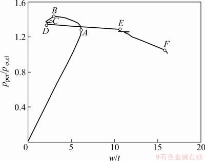
图3 完善圆柱壳的风压下荷载-径向位移曲线
Fig. 3 Load-radial displacement curve of perfect cylinder under wind loading
2.2 完善柱壳的后屈曲
越过初始屈曲荷载后结构进入后屈曲段,荷载下降,径向变形振荡(BCD段),变形分布梯度加大,完善柱壳的后屈曲段是不稳定的。为了顺利跟踪后屈曲路径,荷载增幅控制在0.001pφ,cl以内。从D点到E点,柱壳的屈曲模态发生越跃,原先在φ=20°区域的大波屈曲消退,内凹屈曲变形集中到迎风线中上部,如图4(b)所示。由于迎风线附近向内凹陷,迎风面变得扁平,柱壳截面椭圆化趋势加剧。由于截面的椭圆化,计算位置截面的曲率半径发生变化,Karamanos[17]根据线性理论给出了截面形状改变后的曲率半径计算公式:
 (4)
(4)
式中:R(φ=0)为迎风点的曲率半径;R0为未变形时的圆形截面半径;w0和w1分别为迎风点和计算区段终点的径向位移;△φ为计算区段的角跨度。可见:迎风线上(φ=0°)的曲率半径明显增大,若考虑几何非线性效应,曲率半径的增大更为严重,轴向压力也比线性计算时更大。由于迎风点的曲率半径增大,根据轴压经典屈曲临界应力计算公式
 ,此处所能抵抗的轴向屈曲应力减小。在较大轴压应力的作用下,迎风线中上部区域由E点的大波轴压屈曲模态转变为F点的小波轴压屈曲模态,屈曲波沿环向展开,中心在0.71H处,如图4(c)所示。图4(d)显示了迎风线中上段屈曲变形的变化。F点对应的屈曲模态类似于中等高度圆柱壳在风压下的失稳模态,称其为第二屈曲模态。

图4 完善圆柱壳风压下的屈曲特征
Fig. 4 Buckling characteristic of perfect cylinder
3 开洞圆柱壳的分析
3.1 开洞位置对圆柱壳风压稳定承载力的影响
由于风压呈不均匀分布导致环向应力和轴向应力在壳体内非均匀分布,所以,开洞位置的改变对其抗风稳定承载力影响很大。本文分别选取2种开洞直径下的10个典型位置进行开洞后的有限元计算,结果见表1,其中,d1和d2分别取本文背景工程脱硫塔上的观察孔和检修孔的直径。
C1(x=0.05H,φ=0°,d1=1.71λ0)为在迎风线靠近底部开洞的情况,其荷载-位移曲线和屈曲模态分别如图5(a)和5(b)所示。位移取屈曲中心的径向位移,后续分析均如此。在迎风线底部的开洞削弱了壳体底部边界对迎风线中上部区域的约束,加剧了该区域截面椭圆化的趋势,削弱了局部抵抗轴向压力的刚度,使得结构没有经历类似完善柱壳的第一屈曲模态就直接呈现迎风面中上部的轴压屈曲,屈曲模态类似于完善柱壳的第二屈曲模态。C1情况的抗风稳定承载力明显小于完善柱壳之值,加载到极值点后结构变形有振荡,无稳定后屈曲段,越过极限承载力后沿前屈曲路径卸载。
表1 不同开洞位置的抗风稳定承载力对比
Table 1 Comparison of buckling capacity of cylinder under wind loading with varying cutout position
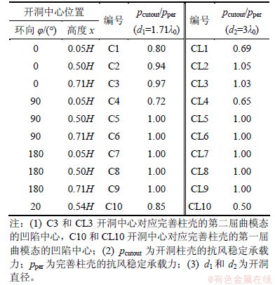
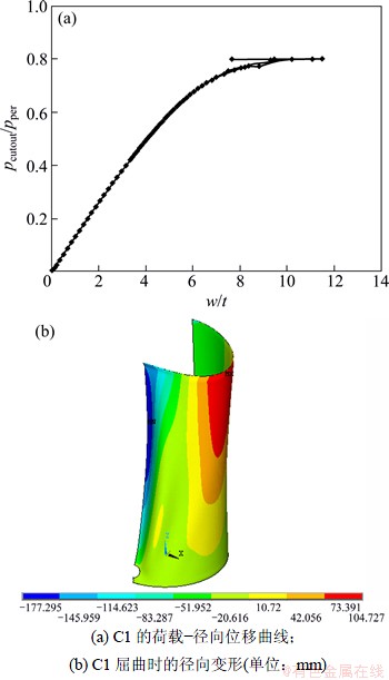
图5 C1的屈曲特征
Fig. 5 Buckling characteristic of C1
C2和C3(φ=0°,d1=1.71λ0)分别为在迎风线中部和上部开洞的情况,荷载-径向位移曲线和屈曲模态分别如图6(a)和6(b)所示。孔洞的存在削弱了柱壳抵抗环向压应力的刚度,应力集中导致洞口的环向邻域内有较大环向压应力,因此,对于这2种情况,柱壳因抵抗环向压应力不足而失稳,呈现出类似于完善柱壳第一屈曲模态的大波屈曲破坏。其稳定承载力小于完善柱壳之值。由于开洞破坏了迎风面上变形的连续性,抑制了柱壳中上部截面的椭圆化趋势,因此,不会发生类似于完善柱壳第二屈曲模态的轴压屈曲。荷载-径向位移曲线同时表明,这2种情况均无稳定后屈曲段。
C4(x=0.05H,φ=90°,d1=1.71λ0)为在侧翼靠近底部开洞的情况。C4最大局部凹陷中心的荷载-径向位移曲线和屈曲模态分别如图7(a)和7(b)所示。可见:C4情况的抗风稳定承载力比完善柱壳的小;越过极值点后,荷载下降,径向变形继续增大。完善柱壳的分析表明,侧翼底部的轴向压应力最大。开洞影响了壳体应力的分布,荷载达到稳定承载力时,开洞环向邻域内的轴向薄膜应力σx可以达到1.32σx,cl,环向薄膜应力σφ达到20σφ,cl。壳体内双向高压应力的存在导致洞口周围发生椭圆形的局部屈曲,圆形孔洞环向两顶点向外凸出,轴向两顶点向内凹陷,洞口形状趋近菱形。越过极值点后,荷载下降,但洞口周围的局部凹陷个数增加,即环向屈曲波数增加,且靠近迎风侧的屈曲波数明显多于背风侧的屈曲波数。在整个加载过程中,壳体除开洞区域的局部屈曲外无整体屈曲发生。
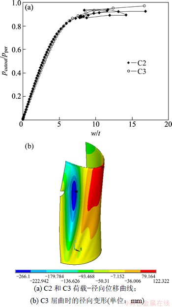
图6 C2和C3的屈曲特征
Fig. 6 Buckling characteristic of C2 and C3
C5~C9(d1=1.71λ0)为洞口在侧翼中上部和背风线的情况。迎风线中上部一结点的荷载-位移曲线如图8(a)所示。可见:这些情况的抗风稳定承载力没有减小。这是因为:在这些情况中,有些洞口区域压应力较小,有些则处在拉应力区,开洞的存在对柱壳抗压刚度的影响不大,所以荷载加到完善柱壳的初始屈曲值时,这些开洞柱壳发生第一模态的屈曲,如图8(b)所示。由于开洞使得壳体变形不连续,在一定程度上抑制了侧翼的外凸变形,减缓了截面的椭圆化趋势,使得壳体在达到初始屈曲荷载后不会因为迎风面抵抗轴压刚度减小而迅速发生第二模态的屈曲,荷载仍能继续增加。由图8(a)可以看出:结构越过完善柱壳的初始屈曲值后,变形有突变,原有的φ=20°位置大波屈曲骤然恢复,迎风面变得扁平;随着荷载继续增加迎风线中上部截面椭圆化趋势加剧,局部抵抗轴向压力刚度减小,当荷载达到极值1.1pper时,该处轴压应力达到最大,开始触发迎风线中上部的压屈破坏,壳体后屈曲模态如图8(c)所示。C5~C9有非常相似的屈曲响应过程,且类似于完善柱壳,其区别只在于开洞柱壳的后屈曲段是稳定的。虽然这些开洞柱壳的极限抗风承载力比完善柱壳的大,但是,当达到完善柱壳的屈曲承载力时,它们也发生了明显的屈曲,按照本文定义,对应初始屈曲模态的荷载为抗风稳定承载力,所以,认为C5~C9开洞柱壳抗风稳定承载力与完善柱壳相等。
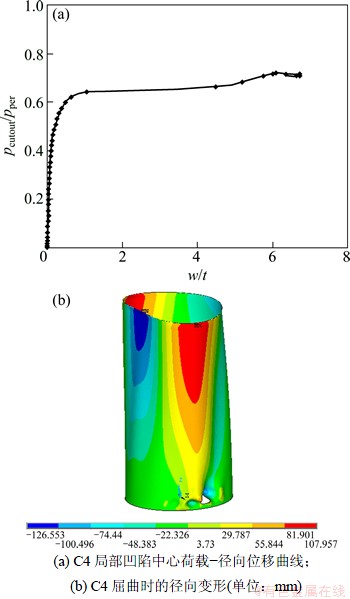
图7 C4的屈曲特征
Fig. 7 Buckling characteristic of C4
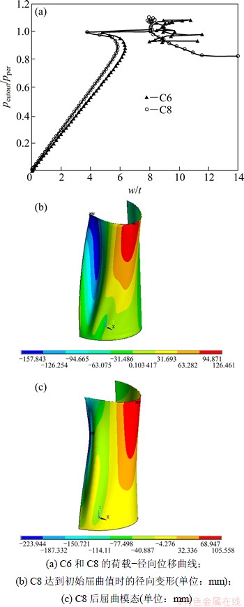
图8 C5~C9的屈曲特征
Fig. 8 Buckling characteristic of C5-C9
C10(x=0.54H,φ=20°,d1=1.71λ0)对应在完善柱壳第一屈曲模态凹陷中心开洞的情况。迎风线上有最大径向位移结点的荷载-位移曲线和屈曲模态分别如图9(a)和9(b)所示,可见C10情况的抗风稳定承载力明显比完善柱壳的小。开洞的存在减小了柱壳抵抗环向压应力的刚度,且在洞口环向邻域内引起很大的环向压应力,因同时存在轴向压应力,在双向压应力的作用下,开洞处发生趋近于菱形形状的局部屈曲变形。迎风线中上部由于较大环向压应力的存在也产生了一个沿轴向延伸的屈曲波。C10无稳定后屈曲段,越过极值点后,结构变形有振荡,随后沿着前屈曲路径卸载。
迎风线上开洞柱壳(φ=0°,d1=1.71λ0)抗风稳定承载力与完善柱壳稳定承载力的比值随开洞高度位置的关系曲线如图10所示。从图10可见:当开洞在迎风线上时,壳体的抗风刚度受到削弱;当迎风线上开洞标高在0.13H以下时,孔洞引起稳定承载力的降低超过10%;开洞标高在0.57H以上时,孔洞引起稳定承载力的降低小于5%。
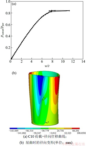
图9 C10屈曲特征
Fig. 9 Buckling characteristic of C10
当开洞在φ=20°时(d=1.71λ0),开洞柱壳抗风稳定承载力随开洞标高的关系曲线如图11所示。从图11可见:开洞高度位置在0.9H以下时,抗风稳定承载力的降幅都超过5%。
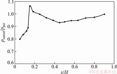
图10 迎风线上开洞高度位置与抗风稳定承载力的关系曲线(φ=0°,d=1.71λ0)
Fig. 10 Relationship curve between buckling capacity and axial position of cutout at windward meridian
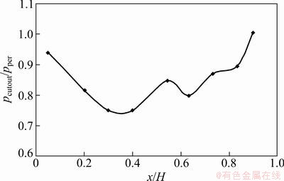
图11 φ=20°时开洞高度位置与抗风稳定承载力的关系曲线(d=1.71λ0)
Fig. 11 Relationship curve between buckling capacity and axial position of cutout when φ=20°
当开洞在靠近底部时(x=0.05H,d1=1.71λ0),柱壳抗风稳定承载力与开洞中心的环向位置关系曲线如图12所示。从图12可见:开洞在底部侧翼时是最不利的,开洞在φ=0°~112°区域时引起柱壳抗风稳定承载力降幅都超过5%,开洞在背风面时影响很小。
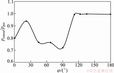
图12 底部开洞时洞口环向位置与抗风稳定承载力的关系曲线(x=0.05H,d=1.71λ0)
Fig. 12 Relationship curve between buckling capacity and circumferential position of cutout close to bottom
3.2 开洞尺寸对圆柱壳风荷载作用下稳定承载力的影响
表1中的CL1~CL10分别对应于在 C1~C10这10个位置的大开洞情况。在迎风线靠近底部开洞时(x=0.05H, φ=0°),柱壳稳定承载力与孔洞直径的关系曲线如图13所示。从图13可见:孔洞直径越大,抗风稳定承载力越低,两者基本呈线性关系,且屈曲模态没有改变。
C2(x=0.5H,φ=0°,d1=1.71λ0)和CL2(d2=3λ0)柱壳屈曲凹陷中心的荷载-径向位移曲线比较如图14所示。从图14可见:小开洞的刚度明显大于大开洞的刚度;在迎风线中部开大洞时(CL2),柱壳抗风稳定承载力比小开洞柱壳的大,没有稳定的后屈曲段,一旦达到第一屈曲模态,结构就破坏,且径向变形十分严重,最大值可以达到38t;在迎风线上部开大洞时(CL3)的屈曲响应与CL2非常相似,稳定承载力比C3的大。
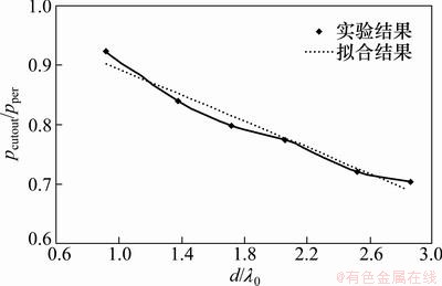
图13 迎风线底部开洞时柱壳抗风稳定承载力与孔洞直径的关系曲线(x=0.05H,φ=0°)
Fig. 13 Relationship curve between buckling capacity and diameter of cutout at windward meridian close to bottom
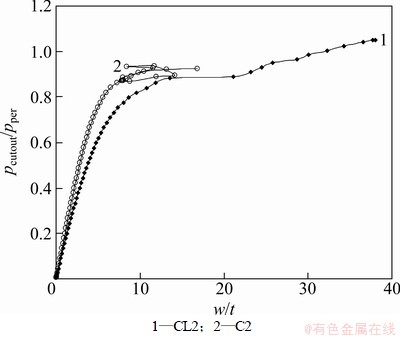
图14 C2和CL2的荷载-径向位移曲线对比
Fig. 14 Comparison between load-radial displacement curves of C2 and CL2
在侧翼靠近底部开洞柱壳(x=0.05H,φ=90°)的抗风稳定承载力与孔洞直径的关系曲线如图15所示。从图15可见:孔洞直径越大,抗风稳定承载力越低,孔洞直径达到λ0后两者基本成线性关系,且屈曲模态均呈现开洞周围的椭圆形局部屈曲。
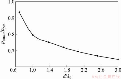
图15 在侧翼底部开洞时柱壳风压下屈曲承载力与孔洞直径的关系曲线(x=0.05H,φ=90°)
Fig. 15 Relationship curve between buckling capacity and diameter of cutout on flank close to bottom
在侧翼中部和上部开大洞时(CL5和CL6),当荷载达到完善柱壳的稳定承载力时,壳体发生第一屈曲模态的失稳,与小开洞不同的是:洞口同时发生局部屈曲变形,环向两顶点外凸,轴向两顶点内凹,开洞形状趋于菱形。此后,荷载不再增长,表明大开洞时无稳定后屈曲段。
在背风线的底部、中部和上部开大洞时(CL7~CL9),柱壳的屈曲路径、屈曲模态与小开洞时完全一致,有稳定后屈曲段,初始屈曲荷载(即抗风稳定承载力)与极限荷载同小开洞时的相等。
在完善柱壳的第一屈曲模态最大凹陷点开洞时,柱壳抗风稳定承载力与孔洞直径的关系曲线如图16所示。从图16可见:柱壳稳定承载力随着孔洞直径的增大而显著降低,屈曲模态与小开洞时保持一致,但达到稳定承载力时屈曲变形幅值增大。
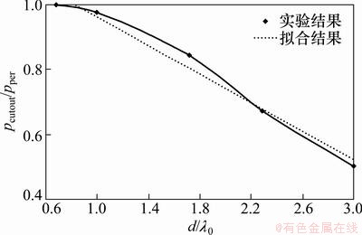
图16 完善柱壳初始屈曲中心开洞时柱壳抗风稳定承载力与孔洞直径的关系曲线(x=0.54H,φ=20°)
Fig. 16 Relationship curve between buckling capacity and diameter of cutout in first buckling mode centre of perfect cylinder
4 有开洞的脱硫塔大型薄壁圆柱壳抗风稳定性验算建议
本文取孔洞引起柱壳抗风稳定承载力降低是否超过5%作为界定孔洞对柱壳抗风有否明显不利影响的标准。当孔洞直径一定,孔洞处在迎风线靠近底部、侧翼靠近底部、完善柱壳第一屈曲模态最大凹陷点这3个典型位置时,比在柱壳上其他区域开洞更为不利。研究柱壳抗风稳定承载力与开洞直径的关系曲线发现:当这3个区域开洞直径d大于0.7λ0时,抗风稳定承载力降低超过5%,开洞的存在对柱壳抗风稳定性有明显不利影响。因此,认为承受风荷载作用的薄壁圆柱壳上开洞直径大于0.7λ0时,孔洞为大洞,显著削弱柱壳抗风稳定承载力;当开洞直径不超过0.7λ0时,孔洞为小洞,对柱壳抗风稳定承载力影响较小。
在实际工程中,脱硫塔并不是一个独立的结构,其烟道出入口均与周围的其他建筑连接,脱硫塔与周围建筑间距较小,考虑周边建筑的阻挡,过风方向并不是任意的。进行抗风稳定验算时,应根据当地的自然气候条件以及塔体过风面积,选择最不利的过风方向作为进行结构抗风验算时的过风方向。对于确定的验算时的过风方向,根据以上对不同位置、不同开洞尺寸脱硫塔圆柱壳抗风稳定承载力的计算,偏于安全地划定在迎风线两侧φ=0°~45°,x=0~0.9H以及φ=45°~112°,x=0~0.3H这2块区域为开洞不利区,在此区域开大洞(d>0.7λ0)的圆柱壳进行抗风稳定性验算时必须考虑开洞的影响。在开洞不利区以外区域开洞,或者在壳体任意位置开洞,但其直径不超过0.7λ0的圆柱壳,进行抗风稳定验算时可以不考虑开洞的影响。
5 结论
(1) 本文研究的完善柱壳(H/R=3.75,R/t=500,底端固定,顶端保持平面)在抗风屈曲路径上首先发生类似于粗矮柱壳承受均匀外部径向压力作用时的屈曲模态,在后屈曲段又跃越为类似于中等高径比柱壳迎风面中上部的轴压屈曲模态。
(2) 研究了在10个不同的典型位置开洞的圆柱壳在风荷载作用下的失稳机理,得到了其屈曲模态和屈曲承载力。
(3) 对于确定的验算时的过风方向,迎风线两侧φ=0°~45°,x=0~0.9H以及φ=45°~112°,x=0~0.3H这2处区域为开洞不利区,在此区域开洞直径大于0.7λ0的圆柱壳进行抗风稳定性验算时应考虑开洞的影响。在开洞不利区以外区域开洞,或者在壳体任意位置开洞,但其直径不超过0.7λ0的圆柱壳,进行抗风稳定验算时可以不考虑开洞的影响。
(4) 在开洞不利区域,随着开洞直径的增大,柱壳抗风稳定承载力降低。在壳体上开洞不利区以外区域开洞时,随着开洞直径的增大,柱壳抗风稳定承载力基本保持不变。
参考文献:
[1] Pircher M. The influence of a weld-induced axi-symmetric imperfection on the buckling of a medium-length silo under wind loading[J]. International Journal of Solids and Structures, 2004, 41: 5595-5610.
[2] Pircher M. Medium-length thin-walled cylinder under wind loading-case study[J]. Journal of Structural Engineering, ASCE, 2004, 130(12): 2062-2069.
[3] Pircher M, Lechner B, Trutnovsky H. The buckling of thin-walled cylinders under wind loading-an experimental study[C]//SHEN Zuyan. Advances in Steel Structures (2). Shanghai: Elsevier, 2005: 1689-1694.
[4] Greiner R, Derler P. Effect of imperfections on wind-loaded cylindrical shells[J]. Thin-Walled Structures, 1995, 23: 271-281.
[5] Godoy L A. Imperfection sensitivity to elastic buckling of wind loaded open cylindrical tanks[J]. Structural Engineering and Mechanics, 2002, 13(5): 533-542.
[6] Toda S. Buckling of cylinders with cutouts under axial compression[J]. Experimental Mechanics, 1983, 23(4): 414-417.
[7] Jullien J F, Limam A. Effects of openings of the buckling of cylindrical shells subjected to axial compression[J]. Thin-Walled Structures, 1998, 31: 187-202.
[8] Hilburger M W, James H, Starnes J R. Buckling behavior of compression-loaded composite cylindrical shells with reinforced cutouts[J]. Non-linear Mechanics, 2005, 40: 1005-1021.
[9] Yeh M K, Lin M C, Wu W T. Bending buckling of an elastoplastic cylindrical shell with a cutout[J]. Engineering Structures, 1999, 21: 996-1005.
[10] Tafreshi A. Buckling and post-buckling analysis of composite cylindrical shells with cutouts subjected to internal pressure and axial compression loads[J]. International Journal of Pressure Vessels and Piping, 2002, 79: 351-359.
[11] 王登峰. 脱硫塔大型薄壁圆柱钢壳结构的承载机理研究[D]. 南京: 河海大学土木工程学院, 2009: 21-38.
WANG Dengfeng. Study on the bearing capacity mechanism of desulphurizing tower structure of large-scale thin-walled steel cylindrical shells[D]. Nanjing: Hohai University, School of Civil Engineering, 2009: 21-38.
[12] 韩强, 黄小清, 宁建国. 高等板壳理论[M]. 北京: 科学出版社, 2002: 111-117.
HAN Qiang, HUANG Xiaoqing, NING Jianguo. Advanced theory of plates and shells[M]. Beijing: Science Press, 2002: 111-117.
[13] Macdonald P A, Kwok K C S, Holmes J D . Wind loads on circular storage bins, silos and tanks: I. Point pressure measurements on isolated structures[J]. Journal of Wind Engineering and Industrial Aerodynamics, 1988, 31(2/3): 165-188.
[14] GB 50009―2001, 建筑结构荷载规范[S].
GB 50009―2001, Load code for the design of building structures[S].
[15] DIN 18800-4, Structural steelwork analysis of safety against buckling of shells[S].
[16] Han H P, Chen J Q, Taheri F, et al. Numerical and experimental investigations of the response of aluminum cylinders with a cutout subject to axial compression[J]. Thin-Walled Structures, 2006, 44: 254-270.
[17] Karamanos A K. Bending instabilities of elastic tubes[J]. International Journal of Solids and Structures, 2002, 39: 2059-2085.
(编辑 杨幼平)
收稿日期:2012-09-12;修回日期:2012-12-09
基金项目:江苏省六大人才高峰资助项目(06-F-018);江南大学自主科研计划项目(JUSRP11250)
通信作者:王登峰(1981-),男,江苏无锡人,博士,讲师,从事大型环保装备结构的研究;电话:15161597381;E-mail:happywdf@126.com

