Operating performance of novel reverse-cycle defrosting method based on thermal energy storage for air source heat pump
АґФґЖЪїЇЈєЦРДПґуѧѧ±Ё(УўОД°ж)2011ДкµЪ6ЖЪ
ВЫОДЧчХЯЈє¶ЅЁпЗ ЅЄТжЗї Т¦Со ХЕС©µ¤
ОДХВТіВлЈє2163 - 2169
Key wordsЈєair source heat pump; thermal energy storage; phase change material; reverse-cycle defrosting
Abstract:
To solve the fundamental problem of insufficient heat available during defrosting while ensuring the efficient and safe system operation for air-source heat pumps (ASHPs). A novel reverse-cycle defrosting (NRCD) method based on thermal energy storage to eliminate frost off the outdoor coil surface was developed. Comparative experiments using both the stand reverse cycle defrosting (SRCD) method and the NRCD method were carried out on an experimental ASHP unit with a nominal 2.5 kW heating capacity. The results indicate that during defrosting operation, using the NRCD method improves discharge and suction pressures by 0.24 MPa and 0.19 MPa, respectively, shortens defrosting duration by 60%, and reduces the defrosting energy consumption by 48.1% in the experimental environment, compared with those by the use of SRCD method. Therefore, using the NRCD method can shorten the defrosting duration, improve the indoor thermal comfort, and reduce the defrosting energy consumption in defrosting.
J. Cent. South Univ. Technol. (2011) 18: 2163-2169
DOI: 10.1007/s11771-011-0958-1![]()
DONG Jian-kai(¶ЅЁпЗ), JIANG Yi-qiang(ЅЄТжЗї), YAO Yang(Т¦Со), ZHANG Xue-dan(ХЕС©µ¤)
Institute of Heat Pump and Air Conditioning of Technology, Harbin Institute of Technology, Harbin 150090, China
? Central South University Press and Springer-Verlag Berlin Heidelberg 2011
Abstract: To solve the fundamental problem of insufficient heat available during defrosting while ensuring the efficient and safe system operation for air-source heat pumps (ASHPs). A novel reverse-cycle defrosting (NRCD) method based on thermal energy storage to eliminate frost off the outdoor coil surface was developed. Comparative experiments using both the stand reverse cycle defrosting (SRCD) method and the NRCD method were carried out on an experimental ASHP unit with a nominal 2.5 kW heating capacity. The results indicate that during defrosting operation, using the NRCD method improves discharge and suction pressures by 0.24 MPa and 0.19 MPa, respectively, shortens defrosting duration by 60%, and reduces the defrosting energy consumption by 48.1% in the experimental environment, compared with those by the use of SRCD method. Therefore, using the NRCD method can shorten the defrosting duration, improve the indoor thermal comfort, and reduce the defrosting energy consumption in defrosting.
Key words: air source heat pump; thermal energy storage; phase change material; reverse-cycle defrosting
1 Introduction
Being energy-saving and environmentally friendly, air-source heat pumps (ASHPs) have been widely used. However, a primary problem that deterred the wider use of ASHP unit was that frost could form on the outdoor coil surface in winter. Over time, frost accumulation on coil surface became sufficient to restrict air passage through the coil, thus reducing the coilЎЇs efficiency [1]. In addition, frost increased the heat transfer resistance between ambient air and coil surface, leading to further performance degradation for the outdoor coil, or even the shutdown of the ASHP unit [2-3].
To improve the operation efficiency of ASHPs, the frost needs to be removed periodically. Defrosting could help the ASHPs return to the rated performance, although the defrosting operation itself consumed energy and caused uncomfortable fluctuation of indoor air temperature. Defrosting could be realized by a number of methods, including hot gas bypass defrosting, electric heat defrosting, reverse-cycle defrosting, and compressor shut down defrosting, etc. Among these methods, the hot gas bypass defrosting and stand reverse cycle defrosting (SRCD) methods were the most widely used for defrosting. However, each of these existing defrosting methods had its own limitations and problems. OЎЇNEAL et al [4] investigated the characteristics of a residential ASHP unit using a reverse-cycle defrosting method. The defrosting started up when the capacity of the heat pump dropped by 20% from its peak capacity. PAYNE et al [5] conducted an experimental study on the defrosting performances with both scroll compressor and reciprocating compressor. HUANG et al [6] compared the hot gas bypass defrosting with reverse-cycle defrosting methods on an air-to-water heat pump. The results showed that the defrosting time when using the hot gas bypass defrosting method was much longer than that when using the reverse-cycle defrosting method, but the indoor thermal comfort using the hot gas bypass defrosting method was better due to lower refrigerant noise, smaller indoor temperature fluctuation and no cold blowing. CHO et al [7] studied the performance of a showcase refrigeration system with multi-evaporator using both on-off and hot-gas bypass defrosting methods. According to the research results, when using hot-gas bypass defrosting method, it had higher refrigerating capacity and less temperature fluctuation than using on-off cycling under frosting/defrosting conditions, but it required more compressor power. BYUN et al [8] investigated the frost retardation of an ASHP using the hot gas bypass defrosting method. In their experiment, when the bypass refrigerant flow rate was 20% of the whole system, the COP and heating capacity were improved by an average of 8.5% and 5.7%, respectively, compared with normal system during 210 min operation. HEWITT and HUANG [9] studied the defrosting performance on a circular shape evaporator ASHP unit using the hot gas bypass method. The author argued the best defrosting initiation condition, defrosting operating time and time intervals. HUANG et al [10] found that the compressor shut down owing to the discharge pressure protection could be effectively avoided using the pre-starting of the fans after reverse-cycle defrosting terminated. Furthermore, JHEE et al [11] found that the heat exchanger with a hydrophobic surface treatment was more effective in aspects of the defrosting efficiency and defrosting time than that with a hydrophilic surface. WANG and LIU [12] fixed an adsorbent bed made of zeolite plates with an active carbon coat behind the outdoor unit of heat pump. In this way, not only did air humidity reduce, but also the air temperature rose because of absorbing heat. KINSARA et al [13] and JAIN and BANSAL [14] designed a liquid dehumidification system for an ASHP system, which could continuously work and gain good results in keeping down the formation of frost.
One of the disadvantages of reverse-cycle defrosting method is that the defrosting energy mainly came from compression power and the energy absorbed from indoor coils. However, the energy from indoor coil was little as the indoor fan was shut down when defrosting. Hence, the defrosting energy was not enough and led to many defrosting problems such as decreased suction pressure, increased defrosting duration and deteriorated indoor thermal comfort. For hot gas bypass defrosting, the frost on the outdoor coil was heated and melted by part of the compressor discharge. Therefore, the energy used to defrost was less and the defrosting duration was longer, compared with the reverse-cycle defrosting. Although there were so many problems in ASHP defrosting operation, the defrosting energy shortage was one of the utmost significance. Up to now, the previous related studies available in the open literature concentrated on the dynamics of reversed-cycle defrosting [15] and the effects of ASHPs components such as throttle regulator and accumulator [16-17]. How to solve the energy shortage problem when defrosting had been seldom studied.
To solve the fundamental problem of insufficient heat available during defrosting, the thermal energy storage based novel reverse-cycle defrosting (NRCD) method with three defrosting modes for ASHPs was developed. Comparative experiments using both SRCD and NRCD methods were carried out on an experimental 2.5 kW nominal heat capacity residential ASHP unit where a phase change material heat exchanger (PCM-HE) was inserted. In this work, a detailed description of the experimental ASHP unit incorporated with the PCM-HE and the experimental procedures were presented, followed by experimental results. Finally, a detailed discussion on the experimental results was presented.
2 Experimental system
2.1 Experimental setup and its instrumentation
The test facility consisted of three major parts: the psychrometric test system, the tested ASHP unit system, and the experimental data acquisition and recording system.
This experiment was carried out by installing the tested ASHP unit in a psychrometric test room. Figure 1 shows the schematic diagram of experimental setup. The psychrometric test room was measured to be 3.12 m (length)ЎБ3.10 m(width)ЎБ2.14 m(height), where a frosting outdoor environment could be simulated by using its existing air conditioning installations, which included heaters of totally 4.8 kW heating capacity, a humidifier of 0.3 kg/h capacity and a cooling coil of 2.8 kW.
The psychrometric test room was located inside a large indoor space where central space heating was separately provided. The outdoor coil of the experimental ASHP unit was placed inside the psychometric test room, while the indoor coil and the phase change material heat exchanger (PCM-HE) were in the large indoor space. Since the output heating capacity of the experimental ASHP unit was relatively small and the existing heating system was thermostatically controlled, the air temperature inside the large environment room was basically able to be maintained at its designed value, irrespective of whether the experimental ASHP unit was operated or not. Hence, the simulated environmental conditions of ASHP indoor and outdoor unit, such as air temperature and air humidity, could be kept constant.
Figure 2 shows the schematic diagram of operation for experimental ASHP unit. The experimental ASHP unit with a rolling rotor compressor used R22 as refrigerant, and the nominal input power and output heat capacity were 850 W and 2.5 kW, respectively.
The PCM-HE inserted into the experimental ASHP unit was a key component to the successful development of the NRCD method. The physical view and construction details of the PCM-HE are shown in Fig.3 and Fig.4, respectively, while the structural parameters are listed in Table 1. After defrosting had terminated, the refrigerant leaving compressor flowed into the PCM-HE firstly, and then into the indoor coil. In this way, the energy of refrigerant could be absorbed and stored in the PCM. When defrost became necessary, the heat stored in the PCM-HE could be used so as to provide sufficient thermal energy to melt the frost off the outdoor coil surface.
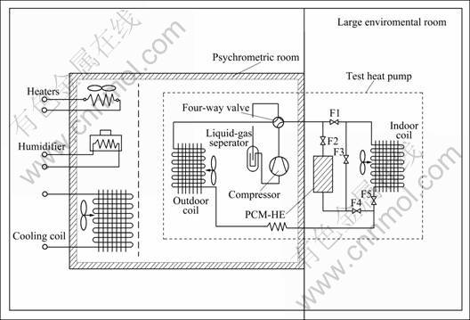
Fig.1 Schematic diagram of experimental set-up
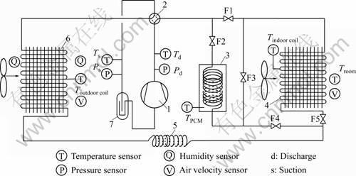
Fig.2 Schematic diagram of operation for experimental ASHP unit: 1ЎЄCompressor; 2ЎЄFour-way valve; 3ЎЄPCM-HE; 4ЎЄIndoor coil; 5ЎЄCapillary tube; 6ЎЄOutdoor coil; 7ЎЄGas-liquid separator; F1 to F5ЎЄSolenoid modulating valves
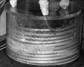
Fig.3 Physical view of PCM-HE
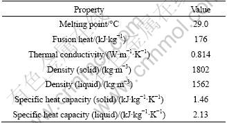
The PCM selected was CaCl2Ў¤6H2O and its thermal properties are listed in Table 2. Furthermore, SrCl2Ў¤6H2O, of which the mass fraction was 2.0%, was mixed in the CaCl2Ў¤6H2O to decrease the degree of super cooling to 0 ЎгC [18].
During experiments, the temperatures of refrigerant and air were measured using temperature sensors (PT1000, Class A). The relative humidities of air at both inlet and outlet of the outdoor coil were measured using a relative humidity sensor (of ЎА1.0% accuracy). Refrigeration pressures were measured using pressure transmitters (of 7.5 kPa accuracy) with a measuring range of 0-3 MPa. The input currents and voltages to the compressor, the indoor and outdoor coil fans were measured by current transmitters (of ЎА0.2% accuracy) and voltage transmitters (of ЎА1.5% accuracy) to evaluate the power inputs. Four air velocity sensors (of ЎА3% accuracy) were fixed evenly at the outlet of outdoor coil.
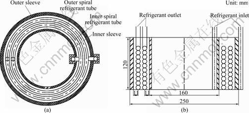
Fig.4 Construction details of PCM-HE used in novel ASHP unit
Table 1 Structural parameters of PCM-HE
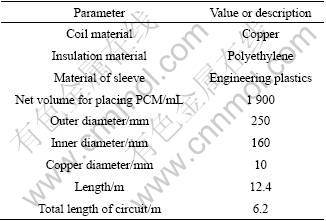
Table 2 Thermal properties of CaCl2Ў¤6H2O
All sensors and measuring devices used in the experimental ASHP unit were able to output direct current signals of 1-5 V or 0-1 V (for relative humidity sensor), which were transferred to a data acquisition unit for logging and recording. The measured data throughout an experimental process were collected and recorded at an interval of 10 s.
2.2 Experimental method and procedure
The experiments were carried out in the environmental chamber with the psychometric test facility. During frosting operation, the air temperature and relative humidity inside the large environment room were maintained at (20.6ЎА0.1) ЎгC and (50ЎА5)%, respectively, and those inside the psychometric room at (-1ЎА0.1) ЎгC and (80ЎА2)%, jointly by use of the experimental ASHP unit, existing heaters and humidifier.
Using the SRCD method, the experimental ASHP unit was firstly operated for heating for 1.5 h, with both Valve F1 and Valve F5 in open position, but Valve F2, Valve F3 and Valve F4 in close position, followed by defrosting operation. The experimental results obtained in this operational mode would provide a base for comparison. Using the NRCD method, the experimental ASHP unit was firstly operated for heating for 1.5 h, followed by defrosting. There were three modes according to the connections between indoor coil and PCM-HE in defrosting. They were series defrosting mode with Valve F2, Valve F3 and Valve F5 in open position, but Valve F1 and Valve F4 in close position, parallel defrosting mode with Valve F1, Valve F2, Valve F4 and Valve F5 in open position, but Valve F3 in close position, and the single defrosting mode with Valve F2 and Valve F4 in open position, but Valve F1, Valve F3 and Valve F5 in close position.
After 90 min frosting operation, the four-way valve was manually reversed to defrosting operation. At the same time, both the indoor and outdoor air fans were turned off. Defrosting operation was manually terminated when the tube surface temperature of the lowest refrigerant circuit of the outdoor coil reached 35 ЎгC. Then, the four-way valve was manually reversed to heating operation, and at the same time, indoor and outdoor air fans were turned on.
During defrosting, the defrosting time was the time period starting from defrosting initiation to termination. The integration cyclic COP was defined as the ratio of the integrated heating output to the integrated energy consumption. Output heating, ?Qc, was calculated using the air flow rate and temperature difference between inlet air and outlet air across the indoor coil as
![]() (1)
(1)
COP was calculated as
![]() (2)
(2)
where W is the electrical power running the ASHP and the indoor and outdoor fans.
3 Results and discussion
Under the exactly same experimental conditions, the defrosting performances when using the NRCD method are different from those when using the SRCD method, as shown in Figs.5-9. The defrosting duration in the NRCD method is 3.0 min and that in the SRCD method is 7.5 min. Therefore, when using the NRCD method, the defrosting duration can be shortened by 60%, as compared with that using the SRCD method. This is because with the use of PCM, adequate energy is provided from the PCM-HE, as compared with taking heat energy from the indoor coil.
3.1 Compressor discharge and suction pressures and temperatures
Figure 5 shows the measured compressor suction and discharge pressures. Under both defrosting methods, when the defrosting operation starts, there are sharp
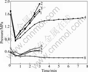
Fig.5 Measured compressor suction pressure and discharge pressure: 1ЎЄDischarge pressure in series defrosting; 2ЎЄDischarge pressure in single defrosting; 3ЎЄDischarge pressure in parallel defrosting; 4ЎЄDischarge pressure in conventional defrosting; 5ЎЄSuction pressure in series defrosting; 6ЎЄSuction pressure in single defrosting; 7ЎЄSuction pressure in parallel defrosting; 8ЎЄSuction pressure in conventional defrosting
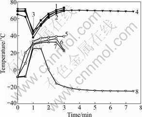
Fig.6 Measured suction temperature and discharge temperature: 1ЎЄDischarge pressure in series defrosting; 2ЎЄDischarge pressure in single defrosting; 3ЎЄDischarge pressure in parallel defrosting; 4ЎЄDischarge pressure in conventional defrosting; 5ЎЄSuction pressure in series defrosting; 6ЎЄSuction pressure in single defrosting; 7ЎЄSuction pressure in parallel defrosting; 8ЎЄSuction pressure in conventional defrosting
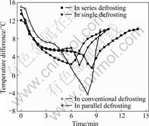
Fig.7 Air temperature difference across indoor coil
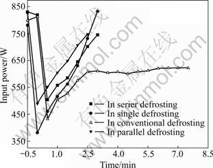
Fig.8 Measured input power to compressor
drops in discharge pressure but sharp increases in suction pressure due to the reverse operation of the four-way valve. At 3.0 min in SRCD method, the suction and discharge pressures are 0.20 MPa and 1.37 MPa, respectively, which are much lower than those of normal heating operation (0.37 MPa and 1.66 MPa, respectively). At the end of defrosting, the suction and discharge pressures reach 0.20 MPa and 1.47 MPa, respectively. In the NRCD method, the suction and discharge pressures are always higher than those in the SRCD method. At 3.0 min, the end of defrosting, the suction and discharge pressures are all above 0.44 MPa and 1.66 MPa, which are 0.24 MPa and 0.19 MPa higher than those in the SRCD method. But in three modes of the NRCD method, the pressures in series defrosting mode is the highest due to the fact that the defrosting energy can be provided by the indoor coil and PCM-HE simultaneously. With a higher suction pressure, it is more likely that the risk of shutting down ASHP unit due to low suction pressure can be avoided, and thus higher operation reliability for the ASHP will be resulted in.
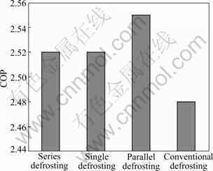
Fig.9 Variations of average system COP
Figure 6 shows the measured discharge and suction temperatures. In the first 1.0 min of defrosting, the suction temperatures in both defrosting methods increase rapidly due to the fact that there are certain amounts of energy stored in indoor coil metal and the refrigerant stored in the pipeline back to compressor. At 1.5 min of defrosting, the suction temperature in SRCD method is 24.7 ЎгC, and the lowest is 31.7 ЎгC in the NRCD method. At 4.0 min, the suction temperature is reached and levels at -23.8 ЎгC in the SRCD method. With such a low suction temperature, there will have no enough energy to melt the frost on the outdoor coil surface and prolong the defrosting duration. When using the NRCD method, the suction temperature in series defrosting mode is the highest due to more energy provided by the indoor coil and the PCM-HE. The variations of discharge temperatures are similar to the suction temperature in both defrosting methods. At the end of defrosting using the NRCD method, the discharge temperatures in the three modes all reach the values of normal heating operation. With higher suction and discharge temperatures, more thermal energy will be provided to melt and evaporate the frost on outdoor coil, and shorten the defrosting operation.
3.2 Defrosting effect on indoor thermal comfort
One of the disadvantages using the SRCD method is that some heat energy supplied to defrost is taken from the indoor environment by the indoor coil, resulting in deteriorated indoor thermal comfort. Figure 7 shows the air temperature difference across the indoor coil. After the defrosting has terminated, the experimental ASHP unit is operated at space heating-resumption period immediately. As seen, after starting the space heating- resumption period, the temperature differences in two defrosting methods both decrease rapidly due to the low temperature of indoor coil during defrosting operation and turning on the indoor coil fan. But the temperature difference in NRCD method is always higher than that in the SRCD method due to a higher temperature of indoor coil. At 8.0 min, it reaches the lowest value of -4.2 ЎгC in the SRCD method. When using the NRCD method, at 6.0, 7.0 and 8.5 min, the lowest temperature differences are 2.4, 2.2 and 1.6 ЎгC in single defrosting, parallel defrosting and series defrosting, respectively. In series defrosting mode, it takes the longest space heating- resumption period, which is 14.0 min. This can be explained by the fact that the heat energy discharged by compressor is absorbed by the PCM in the space heating-resumption period because the refrigerant flows through the PCM-HE firstly. Therefore, after defrosting terminates, the PCM-HE should not be connected into the ASHP unit until indoor environment is satisfied.
3.3 Compressor input power and system COP
Figure 8 shows the measured input powers to compressor. At the beginning of defrosting operation, the input power decreases rapidly due to the reverse operation of the four-way valve. At 2.5 min, the input power to compressor reaches 608.1 W in the SRCD method, and levels at 608.5 W for 2.5 min. At the end of defrosting operation, the input power is 621.6 W, which is lower than that of the normal heating operation. In the NRCD method, after 0.5 min, the input power increases rapidly due to a higher suction pressure and refrigerant mass flow rate. At the end of defrosting operation, the input power reaches 744.8 W. Although the input powers in the NRCD method are much higher than those in the SRCD method, the energy consumption during defrosting is 311.7 kW in the SRCD method and the highest value is 161.6 kW in the NRCD method. Therefore, the energy consumption for defrosting in the NRCD method is reduced by 48.1%, compared with that in the SRCD method, which is due to a shorter defrosting duration.
Figure 9 shows the variations of average COP. In the NRCD method, the average COPs are 2.52, 2.52 and 2.55 for series defrosting, single defrosting and parallel defrosting modes, respectively, which are all slightly higher than 2.48, the COP in the SRCD method. This is due to a shorter defrosting duration.
4 Conclusions
1) Defrosting duration is shortened by 60% when using the NRCD method, as compared with that using the SRCD method in the experimental environment, resulting from more energy available to melt the frost off the outdoor coil.
2) The discharge and suction pressures are increased by 0.19 MPa and 0.24 MPa, respectively, when using the NRCD method, as compared with those using the SRCD method. Therefore, the risk of shutting down an ASHP unit due to a low suction pressure can be avoided, and a higher reliability for the ASHP unit will be resulted in.
3) The input power to compressor is higher using the NRCD method, as compared with that using the SRCD method. However, as the defrosting duration is shorter, the energy consumption for defrosting is reduced by 48.1%. And the COP is slightly higher than that in the SRCD method.
References
[1] BYUN J S, LEE J, JEON C D. Frost retardation of an air-source heat pump by the hot gas bypass method [J]. International Journal of Refrigeration, 2002, 25: 405-413.
[2] KONDEPUDI S N, OЎЇNEAL D L. Effect of different fin configuration on the performance of finned-tube heat exchanger under frosting conditions [J]. ASHRAE Transactions, 1990, 96(2): 439-444.
[3] KONDEPUDI S N, OЎЇNEAL D L. Frosting performance of tube fin heat exchanger with wavy and corrugated fins [J]. Experimental Thermal and Fluid Science, 1991, 4: 613-618.
[4] OЎЇNEAL D L, PETERSON K T, ANAND N K, SCHLIESING J S. Refrigeration system dynamics during the reversing cycle defrosting [J]. ASHRAE Transaction, 1989, 95: 689-698.
[5] PAYNE V, OЎЇNEAL D L. Defrost cycle performance for an air-source heat pump with a scroll and a reciprocating compressor [J]. International Journal of Refrigeration, 1995, 18: 107-112.
[6] HUANG Dong, LI Quan-xu, YUAN X L. Comparison between hot-gas bypass defrosting and reverse-cycle defrosting methods on an air-to-water heat pump [J]. Applied Energy, 2009, 86: 1697-1703.
[7] CHO H Y, KIMA Y C, JANG I K. Performance of a showcase refrigeration system with multi-evaporator during onЁCoff cycling and hot-gas bypass defrost [J]. Energy, 2005, 30: 1915-1930.
[8] BYUN J S, LEEB J H, JEON C D. Frost retardation of an air-source heat pump by the hot gas bypass method [J]. International Journal of Refrigeration, 2008, 31: 328-334.
[9] HEWITT N, HUANG M J. Defrost cycle performance for a circular shape evaporator air source heat pump [J]. International Journal of Refrigeration, 2008, 31: 444-452.
[10] HUANG Dong, YUAN Xiu-ling, ZHANG Xing-qun. Effects of fan-starting methods on the reverse-cycle defrost performance of an air-to-water heat pump [J]. International Journal of Refrigeration, 2004, 27: 869-875.
[11] JHEE S, LEE K S, KIM W S. Effect of surface treatments on the frosting/defrosting behavior of a fin-tube heat exchanger [J]. International Journal of Refrigeration, 2002, 25: 1047-1053.
[12] WANG S W, LIU Z Y. A new method for preventing HP from frosting [J]. Renewable Energy, 2005, 30: 753-761.
[13] KINSARA A A, ELSAYED M M, OMAR M R. Proposed energy-efficient air-conditioning system using liquid desiccouldt [J]. Applied Thermal Engineering, 1996, 16: 791-806.
[14] JAIN S, BANSAL P K. Performance analysis of liquid desiccouldt dehumidification systems [J]. International Journal of Refrigeration, 2007, 30: 861-872.
[15] CHEN Yi-guang, GUO Xing-min. Dynamic defrosting characteristics of air source heat pump and effects of outdoor air parameters on defrost cycle performance [J]. Applied Thermal Engineering, 2009, 29: 2701-2707.
[16] WATTERS R J, OЎЇNEAL D L, DENNIS L. Effect of fin staging on frost/defrost performance of a two-row heat pump evaporator at standard test conditions [J]. ASHRAE Transactions, 2001, 107: 240-249.
[17] MEI V C, DOMITROVIC, R E, CHEN F C, KILPATRICK J K. A frost-less heat pump [J]. ASHRAE Transactions, 2002, 5: 452-459.
[18] XU Y L, LIU D. Preliminary super cooling research on calcium chloride hexahydrate as phase change material [J]. Material Engineering, 2006, Z1: 218-221. (in Chinese)
(Edited by YANG Bing)
Foundation item: Project(50606007) supported by the National Natural Science Foundation of China
Received date: 2010-09-17; Accepted date: 2011-04-19
Corresponding author: JIANG Yi-Qiang, Professor, PhD; Tel: +86-451-86282123; E-mail: jyq7245@163.com

