
Microstructure and mechanical properties of 3D fine-woven punctured
C/C composites with PyC/SiC/TaC interphases
ZENG Fan-hao(曾凡浩)1, 2, XIONG Xiang(熊 翔)1, 2, LI Guo-dong(李国栋)1, 2,
HUANG Bai-yun(黄伯云)1, 2, LUO Jian(罗 健)1, 2
1. State Key Laboratory of Powder Metallurgy, Central South University, Changsha 410083, China;
2. Powder Metallurgy Research Institute, Central South University, Changsha 410083, China
Received 10 August 2009; accepted 15 September 2009
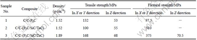
Abstract: The 3D fine-woven punctured C/C-(PyC/SiC/TaC) composites, composed of PyC/SiC/TaC interphases and pyrocarbon (PyC) matrix, were synthesized by isothermal chemical vapor infiltration (ICVI) methods. The alternating layers and the structure of these composites were examined by polarized light microscopy (PLM), X-ray diffractometry (XRD) and scanning electron microscopy (SEM). It is found that the PyC matrix has rough laminar (RL) structure, the TaC layer has NaCl-type cubic structure, and the SiC layer has few wurtzite type 10H-SiC besides β-SiC structure. The effects of fiber coating and the bulk density on the tensile and flexural properties of composites along X or Y and Z direction were investigated. It is shown that fiber coated 3D woven punctured C/C composites have good tensile and flexural strength, and the maximum of flexural strength is 375 MPa in X or Y direction at density of 1.89 g/cm3, which is about three times higher than that of samples without TaC/SiC fiber coating. The flexural strength and bending strength increase with increasing the density of the composites. The analysis of fracture surfaces reveals that fibers and fiber bundles are pulled out in composites, indicating that the composite exhibits a non-linear failure behavior through propagation and deflection of the cracks.
Key words: 3D woven puncture; C/C composites; microstructure; mechanical properties; PyC/SiC/TaC interphases
1 Introduction
Carbon fiber-reinforced carbon matrix (C/C) composites display advantageous properties for structural applications in different fields including exhaust nozzles of aero jet engines, aeroplane disc brakes and nose cone of re-entry flight vehicle due to their low density, high specific strength and low coefficient of thermal expansion at elevated temperatures[1-2]. However, C/C composites have not been actually applied to load-bearing primary structures. This is partly due to a shortage of mechanical data. Hence, the structures cannot be ensured to possess sufficient reliability. Another key factor is carbon starting to oxidize at about 370 ℃[3-4]. The mechanical properties of most C/C composites are degraded by oxidation and the prevention of extensive oxidation of C/C composites represents a real challenge[5].
In order to improve the mechanical properties of composites, the laminated interface was developed by NASLAIN[6-7], BERTRAND et al[8-9], APPIAHA et al[10], LEWIS et al[11] and REBILLAT et al[12] in ceramic matrix composites (CMCs). Through a proper design of the fiber/matrix (FM) interface, which can arrest and deflect cracks formed under load in the brittle matrix, the early failure of the composites can be prevented. It has been postulated that a thin layered compliant material on the fiber surface, such as pyrocarbon (PyC), hexagonal boron nitride (hex-BN), PyC/SiC or BN/SiC, can transfer load and protect fiber effectively. When being loaded at a high enough level, the interfaces have the potential to arrest microcrack propagation by enabling crack deflection and branching, which are responsible for a toughness increasing and non-linear stress―strain behavior for the composites.
On the other hand, extensive investigations have been carried out in an attempt to protect C/C composites against oxidation. For example, SiC was widely used as buffer lay of external coating because of its good compatibility with C/C composites[13-14]. In addition, TaC has been considered a good candidate material with good ablation resistance for C/C composites at ultrahigh temperature due to its high melting point (3 880 ℃), high hardness and stable chemical property[15]. Oxidation of C/C composites occurs preferentially at fiber/matrix (FM) interfacial zones. Although the development of external coatings to protect the composites has been widely pursued, little work has been devoted to fiber coatings as a method of internal oxidation protection. B-C interphases have been shown to protect efficiently carbon fiber against air oxidation. Moreover, boron-rich Si-B-C deposits form a glassy compound at interfacial zones that can block efficiently interfacial carbon oxidation[16].
Since the interphases can not only improve the mechanical properties, but also improve the oxidation resistance of composites, it is essential to analyze and understand the interfacial microstructure and the effects of interphases on the mechanical behavior of the composites. Thus, the focus of this study was to obtain detailed information on the interfacial microstructure and mechanical properties of these C/C composites with PyC/SiC/TaC interphases in order to enable subsequent improvements in the processing.
In the previous study, SiC/TaC coating was fabricated by chemical vapor deposition (CVD) as an external oxidation-resistant coating or by isothermal chemical vapor infiltration (ICVI)[17] as an internal oxidation protection on 3D needle-punctured felt[18]. However, there is a scarcity of published work on the PyC/SiC/TaC interphases by ICVI method and their mechanical effects on C/C composites on 3D fine-woven punctured preforms. In this work, the results of tensile, flexural test at room temperature of 3D fine woven punctured C/C composites with PyC/SiC/TaC interphases and their microstructure were presented in detail. The tensile strength and flexural strength were evaluated by uniaxial tensile test and three-point bending test, respectively, and their deformation mechanisms were discussed. In addition, the effects of the bulk density on the tensile strength and flexural strength of the C/C composites were investigated.
2 Experimental
2.1 Materials and ICVI process
The three dimensional (3D) fine-woven punctured preform is a novel reinforced body which was fabricated by alternatively cross stacked carbon fiber cloth in X and Y directions while using a fine-woven pierced fiber bundles in Z direction. The carbon fiber types of the felts were of PAN based T700 (12 000 carbon fiber tows with each tow containing 12 000 filaments) and the fiber volume fraction of the felt was approximately 42%. The density of the preform was about 0.76 g/cm3. Fig.1 shows the macrographs of 3D fine-woven punctured preform observed by optical microscope.
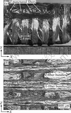
Fig.1 Morphologies of 3D fine-woven punctured preform in X-Y plane(a) and X-Z plane(b) by light microscopy
Details of the ICVI fabrication process, parameters, and reactor system for this composite have been previously described by LI et al[15, 18] and CHEN et al[17]. Briefly, during the ICVI process, the reagent gases flow through the 3D fine-woven carbon preforms. The PyC layer was first deposited on fibers from a mixture of propylene (C3H6), hydrogen and nitrogen gas at about 950 ℃. The SiC layers were deposited from a mixture of methyltrichlorosilane (CH3SiCl3, MTS), argon and hydrogen at 1 000 ℃. While TaCl5-Ar-C3H6- H2 system was used as source material to deposit TaC layer, where TaCl5 powders were evaporated in a stainless steel container at 180 ℃ and transported into the reactor by an Ar carrier gas and the depositing temperature was maintained at 800 ℃. Before being heated to the designed temperature, the preforms were heated for a long period of time in deposition chamber under vacuum to get rid of adsorbed moisture. After the deposition of PyC/SiC/TaC interphases, the preforms were further densified with pyrocarbon by ICVI method.
2.2 Mechanical tests and structure characterization
Mechanical behavior was examined in two types of C/C-PyC (sample 1) and C/C-(PyC/SiC/TaC) (samples 2 and 3) composites, which were reinforced with carbon fiber T700. The test specimens were cut from the part parallel (X or Y direction) and perpendicular (Z direction) to the fiber plies. At least 5 specimens were tested for each testing condition.
Dog-bone tensile specimens, shown in Fig.2, were used for the tensile tests. Three-point-bending tests were carried out to measure flexural strength and the dimension of the bars was 55 mm×10 mm×4 mm with a support span of 40 mm. The failure flexural stress is given by the following equation:
 (1)
(1)
where f is the measured load at fracture (N); l is the support span distance (mm); b is the width of the specimen (mm); and h is the specimen thickness (mm). All tests were performed using an Instron 3369 mechanical testing machine under a crosshead speed of 1 mm/min.

Fig.2 Geometry and dimensions of dog-bone-shaped tensile test-specimens
The bulk density was determined by Archimedes’ method. The crystal structure and microstructures of the composites were characterized by X-ray diffractometer (XRD) with a D/max-2550 VB using Cu Kα1 radiation (λ=1.540 6 ?), optical microscope (OM, Lecia MeF3) with polarizer, and scanning electron microscope (SEM, JSM-6360LV), respectively.
3 Results and discussion
3.1 Metallography
Fig.3 shows typical OM images of as-produced composites, viewed in Z direction. Cross-sectional micrographs of fibers are observed which are composed of concentric interphases and pyrocarbon matrix, and many pores/voids are also observed in both interbundle and intrabundle regions. Three layers with different optical color and thickness can be distinguished in Figs.3(a) and (b). The inner rings, which are observed around fibers in Fig.3(b), are PyC layers. Next about 8-9 μm-thick gray layer and 1 μm-thick golden yellow layer are observed around the fiber which can be recognized to be SiC and TaC, respectively.
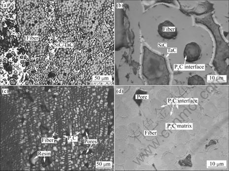
Fig.3 Optical microscopy images of 3D fine-woven punctured C/C composites: (a) Composites with PyC/SiC/TaC interphases; (b) Partially enlarged view of (a); (c), (d) Composites with only PyC interphases
To compare the microstructure changes of composites without SiC/TaC interphases, the OM images of the C/C-PyC composites prepared by the same process are also shown in Figs.3(c) and (d). It can be observed that the PyC interface (as marked in Fig.3(d)) has a width less than 300 nm and is well aligned around the transverse fiber surface. According to the classification method proposed by LIEBERMAN and PIERSON[19], the textures of the deposited pyrocarbon are classified into three main types, e.g. smooth laminar (SL), rough laminar (RL), and isotropic (ISO). Under polarized light, the pyrocarbon matrix is in the typical blue-and-yellow polarized light contrast, with various amounts of growth cones (columnar texture) and sharp Maltese cross, indicating that the matrix is rough laminar (RL) pyrocarbon, i.e. highly anisotropic carbon (see Fig.3(c))[19-20].
3.2 X-ray diffraction analysis
Fig.4 shows the typical X-ray diffraction (XRD) patterns of as-produced C/C-PyC/SiC/TaC composites and the image of corresponding XRD sample. It can be observed that the strong and widened peaks at 2θ=26?, 44? and 77? correspond to (002), (101) and (110) planes of the HCP structure carbon. Reflections from TaC (111), (200), (220), (311) and (222) planes are observed in the spectrum. Likewise, the peaks of FCC structure β-SiC are also shown in the XRD pattern, indicating that the composites consist of carbon, TaC and SiC phases. It is noticeable that there are some peaks at 2θ=33.7?, 36.3?, 38.1? and 64.5?, which are determined to be the reflections from 10H-SiC phases according to JCPDS card number 89-2214[21].
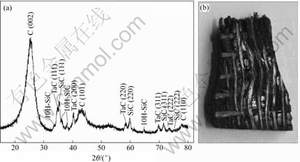
Fig.4 Typical XRD pattern of C/C-PyC-SiC-TaC composites (a) and image of corresponding XRD sample (b)
The carbon peaks of XRD pattern are contributed to carbon fiber and pyrocarbon, and the XRD pattern of the carbon exhibits a relatively broad diffraction peak, indicating the low degree of graphitization of the carbon fiber and pyrocarbon. TaC has NaCl-type cubic structure with lattice constant a=4.45 ?, but SiC occurs in many different polytypes including low-temperature stable phase of 3C(β)-SiC (cubic, zinc blende type) and high-temperature stable phases of 2H-, 4H-, 6H-, 10H-, 15R-SiC, etc., where H is wurtzite type hexagonal unit cell, R is rhombohedral unit cell, and the number corresponds to the layers of stack period along c-axis. The carbon atom is positioned at the center of mass of the tetragonal structure outlined by the four neighboring Si atoms so that the distance between the C atoms and each of the Si atoms is the same, approximately 1.89 ?. In general, the SiC structure of CVI process is 3C(β)-SiC because the growth temperature is much lower than 1 700 ℃. However, the 10H-SiC is clearly observed in the samples. This may be attributed to local non-stability of temperature and pressure during CVI, which can result in the stacking faults during the growth of SiC[22].
3.3 Mechanical properties
3.3.1 Tensile behavior
Fig.5 shows the tensile stress versus strain of a 3D C/C composite at room temperature in X or Y direction (Fig.5(a)) and Z (Fig.5(b)) direction, and the nonlinear curves indicate that the composites have non-linear behavior under tensile loading. Inserted pictures are the typical fracture macrographs of tensile specimens 3 and 1. Table 1 summarizes the results of the tensile and flexural tests. In Fig.5, all the curves are mainly composed of two parts: the initial nonlinear part with a reduction in slope and the pseudo-linear part with a relative stable slope. From Fig.5(a), it can be seen that the failure strength and elongation of the C/C-PyC (sample 1) are 132 MPa and 4.3%, respectively. The transition stress is about 35 MPa with a strain of 0.38%. When SiC/TaC interphase is deposited onto the fiber surface, the failure strength and elongation of the sample 2 (ρ=1.52 g/cm3) are decreased to 100 MPa and 1.2%, while sample 3 (ρ=1.89 g/cm3) has ultimate tensile strength of 168 MPa at strain of 2.2%, much higher than those of samples 1 and 2. The transition stress of sample 2 is about 58 MPa with a strain of 0.31%, and the sample 3 has a higher transition stress of 60 MPa and smaller strain of 0.25% as the composite density increases from 1.52 to 1.89 g/cm3.
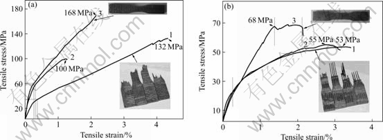
Fig.5 Stress―strain curves for 3D fine-woven punctured C/C composites under tensile loading: (a) In X or Y direction; (b) In Z direction (Inserted images are fracture macrographs of tensile specimens): 1-C/C-PyC; 2-C/C-PyC-SiC-TaC (ρ=1.52 g/cm3); 3-C/C-PyC-SiC-TaC (ρ=1.89 g/cm3)
Table 1 Tensile and flexural mechanical properties of C/C composites
The composites possess different tensile behaviors when loading in Z direction (see Fig.5(b)). The samples 1 and 2 have the same trends composed of only one initial non-linear part with low failure strength of 53 MPa and 55 MPa respectively, but sample 3 has obviously non-linear behavior with three parts including initial non-linear part with a reduction in slope, the second pseudo-linear part with a relative stable slope and the third pseudo-plastic part. On the other hand, the tensile strength of specimens in Z direction is smaller than that in X or Y direction, which can be explained in terms of fiber architectures. There are few punctured Z-fiber bundles in tensile specimens (see inserted images of Fig.5(b)), As a result, there are much lower contents of bearing fibers compared with X or Y direction, when being subjected to tensile test with the same section area.
The interfaces in the composites play an important role in tailoring and optimizing toughness and strength. The functions of interphases are: 1) acting as a mechanical fuse, i.e. to deflect the matrix microcracks and 2) maintaining a good load transfer between the fiber and matrix[7]. In the as-produced composites, the interface includes two types. One is between the fiber, matrix and the interphase, and the other is between the interphases. The interphase in the C/C (sample 1) composites is the pyrocarbon layer between fiber and matrix, while the interphase in the samples 2 and 3 is PyC/SiC/TaC. Therefore, there is a larger interface area in samples 2 and 3 than in sample 1 for a given volume fraction of fibers. During tensile loading, matrix microcracks loaded to failure depend first of all on the interphase bonding strength. Therefore, owing to the high number of cracks produced during this deflection, damaging mode appears as a highly dissipating mechanism and results in a higher strength of sample 3.
However, if interface bonding is very strong, stress concentration can cause fiber fracture and there are then no bridging fibers. Conversely, decreasing the interface sliding resistance promotes interface debonding, leading to long fiber pulling-out and high strength and ductility. Thus, the large strain in sample 1 might be maintained by the entangled fiber bundle with weak interfaces, not in bundles with strong PyC interfaces than that of samples 2 and 3(see Fig.6(b)).
The fracture surfaces of fiber bundles for the tensile specimen are shown in Fig.6. As shown in Fig.6(b), the fractures of sample 2 mainly occur at the cross-over of the fiber, and the fibers are subjected to extensive pulling-out among fiber bundles. The interface cracks and a few residual interphases surrounding the fiber are observed. However, sample 1 (see Fig.6(a)) has relatively smooth surface and step-like fracture morphology in fiber bundles, indicating that the nature of brittle fracture in C/C composites.
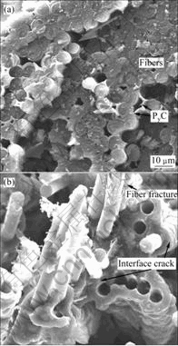
Fig.6 SEM images of fracture surface for composites under tensile test in X or Y direction: (a) C/C-PyC (ρ=1.52 g/cm3); (b) C/C-PyC-SiC-TaC (ρ=1.52 g/cm3)
There are extensively pre-exiting cracks in the composites including intra yarn cracks located in the transverse tows and inter yarn cracks formed during the processing at high temperature and the subsequent cooling down cycles. Unlike the pure ceramic of brittle fracture with a typical linear curve, the tensile behavior of C/C composites exhibits brittle fracture characteristic with nonlinear behavior due to the propagation of cracks in the composites. Under low tension, the stress was centralized at the voids and intersection of materials, which can induce crack initiation. The initiated microcracks and pre-exiting cracks begin to extend and can be deviated by passing through interface due to the radial tension stress and axial shear stress of the interface. Under this condition, the slope of stress―strain curve decreases gradually following the parabolic curve (see the first part of the curves in Fig.5).
When the stress is increased to a threshold value of matrix fracture, the microcracks influx to macrocracks and the cracks tend to saturate. At this time, the load is transferred to the fiber gradually with the fragmentation of the matrix, thus the strain is increased rapidly. Moreover, the debonding and sliding generate between fibers and interfaces accompanying with fiber fracture and pulling-out (see Fig.6(a)). In this situation, the slope of stress―strain curve is decreased rapidly, showing the parabolic curve. Finally, large fibers are damaged and ruptured by the dry friction of fiber with interfaces or matrix with the stress increasing, which results in the failure of composites.
3.3.2 Flexural behavior
Fig.7 shows a typical load―displacement curve for the 3D fine-woven punctured C/C composites. It is observed that the failure behavior of the composites is strongly dependent on the interphases and density. For the composites with a pyrocarbon interlayer (Fig.7(a), sample 1), the flexural behavior shows an inelastic response in the initial stage with the maximum failure load of 260 N (97.5 MPa), followed by a very slow decrease in load with long displacement, representative of inelastic or plastic deformation. In sample 1, a continuous pyrolytic carbon layer can result in a weak interfacial bonding, which makes the debonding easier and crack branching occur; therefore, fiber bundles are pulled out, resulting in the strain increasing. In contrast, the composites with SiC/TaC interphases exhibit nonlinear behavior with much higher failure strength but poorer fracture displacement. After the stress increases to its maximum value, the stress then decreases into pseudo-plastic stage. The highest strength is achieved by specimens with the higher density of 1.89 g/cm3 (sample 3) wherein on average a nearly 400 % increase over the SiC/TaC-uncoated specimens (sample 1) is attained.
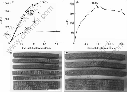
Fig.7 Typical load―displacement curves for 3D fine-woven punctured C/C composites under flexural loading in X or Y direction(a) and Z direction(b) (1-C/C-PyC; 2-C/C-PyC-SiC-TaC (ρ=1.52 g/cm3); 3-C/C-PyC-SiC-TaC (ρ=1.89 g/cm3)) and typical fracture macrographs of samples after flexural testing corresponding to X or Y direction(c) and Z(d) direction
Similar to the tensile test, there are few punctured Z-fiber bundles in flexural specimens; therefore, there are much lower contents of bearing fibers compared with X or Y direction, when being subjected to test with the same section area. Thus, the bending strength of the composites in Z direction is much lower than that in X or Y direction (see Fig.6(a)).
The mode of failure of C/C composite with interphases in flexure is complex. The most common modes of failures are transverse splitting, compressive failure due to fiber kinking, intralaminar shear failure, interfacial shear failure, and brittle tensile failure with fiber pulling-out. The matrix material is generally more brittle than the fiber and usually has a lower ultimate strain. Thus, as the specimen bends the matrix is likely to develop a series of cracks with the initiation and propagation of cracks depending not only on the type and positioning of the reinforcement, but also on the strain capacity of the matrix. Under tension, the composite matrix can failure either longitudinally or transversely by slight shear or compressive fracture, not only by simple brittle tensile fracture. Thus, the damage of matrix makes it lose the supporting and constraints to fiber skeleton, which causes the fiber bundles distorted and bended. After the matrix crack appears, the stress on the fiber goes up. This region corresponds to the initial non-linear region of the stress―strain curve for the composite. Then, the fiber takes up a major part of the load as it bridges the matrix cracks and fiber-matrix debonding, where the fiber is fractured and pulled out.
In general, the stereo net distributions of fibers are main unit for load bearing in the composites under external loading. As the density of composites increases, much matrix is filled into pores between fiber bundles. Thus, the bonding strength between carbon fiber and fiber bundles is increased and the area of bearing load is increased; then, the strength of composites is improved. On the other hand, high density means low flaws and cracks in the composites, which decreases the cracks propagation in per unit area and enhances the flexural strength. This is why the sample 3 has much higher strength than that of sample 2 or sample 1[23-24].
4 Conclusions
Three 3D fine-woven punctured C/C composites with PyC/SiC/TaC interfaces were developed by isothermal chemical vapor infiltration method. The structure and mechanical properties, including influence of the interface and the bulk density on the tensile and flexural properties were investigated. The bulk densities of the composites were 1.52 g/cm3 and 1.89 g/cm3. From this investigation, the following important conclusions are derived.
1) The microstructure of pyrocarbon matrix is rough laminar (RL) by the polarized light microscopy, and the TaC interphase has NaCl-type cubic structure. The SiC layer has β-SiC structure but few wurtzite type 10H-SiC structures are observed by XRD.
2) The mechanical properties of as-fabricated composites tested in X or Y direction are much higher than those of Z direction due to the architecture of fiber felt. PyC/TaC/SiC interphases can improve the mechanical properties of the 3D fine-woven punctured C/C composites. With the same density of 1.52 g/cm3, the flexural strength for the C/C-(PyC-SiC-TaC) composites is 310 MPa, which is about three times that of C/C-PyC composites.
3) The flexural and bending strength increase with increasing the density of the composites. As the density of the C/C-(PyC-SiC-TaC) composites increases from 1.52 to 1.89 g/cm3, the tensile strength of the composites in X or Y direction increases from 100 MPa to 168 MPa, and the flexural strength increases from 310 MPa and 375 MPa.
4) The C/C-(PyC-SiC-TaC) composites exhibit a non-linear failure behavior because the interfaces have the potential to arrest microcrack propagation by enabling crack deflection and branching of the cracks.
References
[1] BUCKLEY J D. Carbon-carbon, an overview [J]. Am Ceram Soc Bull, 1988, 67(2): 364-368.
[2] STRIFE J R, SHEEHAN J E. Ceramics coatings for carbon-carbon composites [J]. Am Ceram Soc Bull, 1988, 67(2): 369-374.
[3] McKEE D W. Oxidation behavior of matrix-inhibited carbon/carbon composites [J]. Carbon, 1988, 26(5): 659-665.
[4] SHEEHAN J E. Oxidation protection for carbon fiber composites [J]. Carbon, 1989, 27(5): 709-715.
[5] LAHAYE J, LOUYS F, EHRBURGER P. The reactivity of carbon-carbon composites [J]. Carbon, 1990, 28(1): 137-141.
[6] NASLAIN R. Design, preparation and properties of non-oxide CMCs for application in engines and nuclear reactors: An overview[J]. Compos Sci Technol, 2004, 64: 155-170.
[7] NASLAIN R. The design of the fiber-matrix interfacial zone in ceramic matrix composites [J]. Composites Part A, 1998, 29A: 1145-1155.
[8] BERTRAND S, DROILLARD C, PAILLER R, BOURRAT X, NASLAIN R. TEM structure of (PyC/SiC)n multilayered interphases in SiC/SiC composites [J]. J Eur Ceram Soc, 2000, 20: 1-13.
[9] BERTRAND S, PAILLER R, LAMON J. SiC/SiC minicomposites with nanoscale multilayered fibre coatings [J]. Compos Sci Technol, 2001, 61: 363-367.
[10] APPIAHA K A, WANG Z L, LACKEY W J. Characterization of interfaces in C fiber-reinforced laminated C-SiC matrix composites [J]. Carbon, 2000, 38: 831-838.
[11] LEWIS J S, LACKEY W J, VAIDYARAMAN S. Model for prediction of matrix microstructure for carbon/carbon composites prepared by forced flow-thermal gradient CVI [J]. Carbon, 1997, 35: 103-112.
[12] REBILLAT F, LAMON J, GUETTE A. The concept of a strong interface applied to SiC/SiC composites with a BN interphase [J]. Acta Materialia, 2000, 48: 4609-4618.
[13] SMEACETO F, FERRARIS M. Oxidation protection multilayer coatings for carbon-carbon composites [J]. Carbon, 2002, 40: 583-587.
[14] YAN Zhi-qiao, XIONG Xiang, XIAO Peng, CHEN Feng, ZHANG Hong-bo, HUANG Bai-yun. A multilayer coating of dense SiC alternated with porous Si-Mo for the oxidation protection of carbon/carbon silicon carbide composites [J]. Carbon, 2008, 46: 149-153.
[15] LI Guo-dong, XIONG Xiang, HUANG Bai-yun. Microstructure characteristic and formation mechanism of crackfree TaC coating on C/C composite [J]. Trans Nonferrous Met Soc China, 2005, 15(6): 1206-1212.
[16] LABRUQUERE S, BLANCHARD H, PAILLER R, NASLAIN R. Enhancement of the oxidation resistance of interfacial area in C/C composites. Part Ⅱ: oxidation resistance of B-C, Si-B-C and Si-C coated carbon preforms densified with carbon [J]. J Euro Ceram Soc, 2002, 22: 1011-1021.
[17] CHEN Zhao-ke, XIONG Xiang, HUANG Bai-yun, LI Guo-dong, XIAO Peng, WANG Ya-lei, WANG Qiong. Oxidation mechanisms of C-SiC-TaC-C composites prepared by chemical vapor infiltration [J]. Trans Nonferrous Met Soc China, 2007, 17: s145-s149.
[18] LI Guo-dong, XIONG Xiang, HUANG Bai-yun, HUANG Ke-long, Structural characteristics and formation mechanisms of crack-free multilayer TaC/SiC coatings on carbon-carbon composites [J]. Trans Nonferrous Met Soc China, 2008, 18: 255-261.
[19] LIEBERMAN M L, PIERSON H O. Effect of gas phase conditions on resultant matrix pyrocarbons in carbon/carbon composites [J]. Carbon, 1974, 12(3): 233-241.
[20] OBERLIN A. Pyrocarbons [J]. Carbon, 2002, 40: 7-24.
[21] The Joint Committee on Powder Diffraction Standards, International Centre for Diffraction Data [Z]. Swarthmore, Pennsylvania, USA, 1998.
[22] KUNIHITO K, SHUNJI T, CHUL H P, TAKAYORI S, HIROAKI Y. High-resolution electron microscopy observations of stacking faults in β-SiC [J]. J Am Ceram Soc, 1989, 72(10): 1985-1987.
[23] BUSSIBA A, KUPIEC M, PIAT R, BOHLKE T. Fracture characterization of C/C composites under various stress modes by monitoring both mechanical and acoustic responses [J]. Carbon, 2008, 46: 618-630.
[24] XIONG Xiang, HUANG Bai-yun, LI Jiang-hong, WU Feng-qiu. Bending property and fracture mechanism of quasi-3D C/C composites [J]. Journal of Aeronautical Materials, 2006, 26(4): 88-91. (in Chinese)
Foundation item: Project(50872154) supported by the National Natural Science Foundation of China; Project(20080431029) supported by China Postdoctoral Science Foundation; Project supported by the Postdoctoral Science Foundation of Central South University, China
Corresponding author: ZENG Fan-hao; Tel: +86-731-88877880; E-mail: zengfanhao608@mail.csu.edu.cn
DOI: 10.1016/S1003-6326(09)60045-5
(Edited by YANG Bing)

