Improved estimation of rotor position for sensorless control of a PMSM based on a sliding mode observer
��Դ�ڿ������ϴ�ѧѧ��(Ӣ�İ�)2016���7��
�������ߣ�Wahyu Kunto Wibowo Seok-Kwon Jeong
����ҳ�룺1643 - 1656
Key words��rotor position estimation; permanent magnet synchronous motor; sliding mode observer; adaptive observer gain; cascade low-pass filter; variable cut-off frequency; variable phase delay compensation
Abstract: This work proposes a new strategy to improve the rotor position estimation of a permanent magnet synchronous motor (PMSM) over wide speed range. Rotor position estimation of a PMSM is performed by using sliding mode observer (SMO). An adaptive observer gain was designed based on Lyapunov function and applied to solve the chattering problem caused by the discontinuous function of the SMO in the wide speed range. The cascade low-pass filter (LPF) with variable cut-off frequency was proposed to reduce the chattering problem and to attenuate the filtering capability of the SMO. In addition, the phase shift caused by the filter was counterbalanced by applying the variable phase delay compensation for the whole speed area. High accuracy estimation result of the rotor position was obtained in the experiment by applying the proposed estimation strategy.
J. Cent. South Univ. (2016) 23: 1643-1656
DOI: 10.1007/s11771-016-3219-5

Wahyu Kunto Wibowo1, Seok-Kwon Jeong2
1. Department of Electrical Engineering, Universitas Pertamina, Jakarta 12220, Indonesia;
2. Refrigeration and Air-Conditioning Engineering, Pukyong National University, Busan 608-739, Korea
 Central South University Press and Springer-Verlag Berlin Heidelberg 2016
Abstract: This work proposes a new strategy to improve the rotor position estimation of a permanent magnet synchronous motor (PMSM) over wide speed range. Rotor position estimation of a PMSM is performed by using sliding mode observer (SMO). An adaptive observer gain was designed based on Lyapunov function and applied to solve the chattering problem caused by the discontinuous function of the SMO in the wide speed range. The cascade low-pass filter (LPF) with variable cut-off frequency was proposed to reduce the chattering problem and to attenuate the filtering capability of the SMO. In addition, the phase shift caused by the filter was counterbalanced by applying the variable phase delay compensation for the whole speed area. High accuracy estimation result of the rotor position was obtained in the experiment by applying the proposed estimation strategy.
Key words: rotor position estimation; permanent magnet synchronous motor; sliding mode observer; adaptive observer gain; cascade low-pass filter; variable cut-off frequency; variable phase delay compensation
1 Introduction
A permanent magnet synchronous motor (PMSM) has been receiving high attention in various industry fields for many adjustable speed and position applications. Modern PMSMs have the ability to produce constant torque [1], high power density, high efficiency, fast dynamics, and rugged structure. The vector control, referred as a field-oriented control (FOC), is required to achieve the high control performance of a PMSM [2-3]. Correct rotor angular position information is necessary for the vector control. Hence, small torque ripple and smooth operation of the speed can be obtained in the vector control of a PMSM. Usually, a high precision mechanical sensor such as an encoder or a resolver is used to obtain the rotor angular position. However, the existence of the mechanical sensor would increase the cost production and the size of the PMSM. In addition, the mechanical sensor is very sensitive to environmental constraints such as vibration and temperature. Therefore, it spoils the control reliability and limit the applications.
The sensorless control or encoderless control has been a challenging subject of interest to researchers for the last decade. The absence of the physical sensor will escalate the system reliability, reduce the cost of production, and minimize the size of the PMSM. There are two main categories of sensorless control with specific regard for PMSMs: saliency-based method and model-based method. The saliency-based method exploits the magnetic saliency of the motor by injecting some signal into the system, and then regaining the motor angular position and speed by demodulating the resulting signal produced by the carrier excitation [4-5]. There are two basic saliency methods exist in this category. The first method is based on high-frequency carrier signal injection [6-11] and the second method is based on proper selection of inverter switching pattern [12-13]. All of these latest works that adopt the signal injection method allow the drive to work with high control performance even in the low-speed and standstill operation. However, some drawbacks are present for those methods. The injected signal will cause noise into the system that makes degradation to the control performance, and the system will fail to work in certain threshold speed. Furthermore, this method will not properly work on a surface mounted type PMSM because of its non-saliency characteristic.
On the other hand, the model-based method does not have those limitations. The model-based method exploits a dynamic model of the motor to obtain the back electromotive force (EMF) or flux linkage. In particular, the estimated back-EMF is exploited to calculate the rotor angular position and speed. However, this method is only suited for medium to the high-speed operational range because the measured back-EMF was too small at the low-speed operation. Furthermore, the model-based method is sensitive to the variation of the motor parameter because it depends on a mathematical motor model. Many existing research employs a model-based method to obtain the rotor angular position and speed because this method does not need additional hardware. The Luenberger observer and the model reference adaptive system (MRAS) have been used to estimate the rotor angular position and speed for sensorless control of a PMSM [14-18]. Those two approaches were successful to estimate the rotor angular position in the medium to high-speed range. However, those two methods were very sensitive to motor parameter variation. Thus, achieving good performance by using those methods was a difficult task in the low-speed operation. Many researchers adopted the Kalman filter as the system observer [19-24]. This approach has been widely used to estimate the rotor angular position for sensorless control of a PMSM considering the statistical characteristics of the system model error and the measurement noise. The Kalman filter can improve the estimation accuracy of the low-speed operation. However, the Kalman filter includes vector and matrix calculations that make computationally intensive. Furthermore, it is a difficult task to decide the covariance matrices and its initial values in the Kalman filter approach to avoid system instability.
The sliding mode observer (SMO) has attractive features of easiness in mathematical design and robustness to the system parameter variation, disturbance, and noise compared to other observers of the model- based method [25]. The SMO has been applied by many researchers on sensorless control of a PMSM [26-34]. The estimation of the back-EMF based on the SMO was giving a satisfactory result, which is resulting in a good estimation of the rotor angular position and speed. However, those outcomes only obtained when the SMO works in the medium to high-speed operation. The chattering problem that caused by the supply noise, switching frequency, and the discontinuous function have been remained as the main drawback of the SMO approach. This chattering will be magnified by the constant observer gain of the SMO, which makes the estimation results of the back-EMF fail especially in the low-speed operation. Currently, there are several options for the SMO to estimate the back-EMF by using the discontinuous control functions such as signum, saturation, and sigmoid. The saturation function is easy to implement on the microprocessor and effective enough to lessen the chattering phenomenon compared to other discontinuous functions. A low-pass filter (LPF) usually takes place in the SMO to reduce the chattering problem on the back-EMF estimation. Usually in the SMO, the rotor angular position is calculated from the estimated back-EMF by using the arc-tangent mathematical operation. The position accuracy result of those methods is highly influenced by the existence of the noises and harmonics on the estimated back-EMF. The obvious estimation error will occur especially at the zero crossing of the back-EMF [35-37]. The usage of the LPF with proper cut-off frequency and phase delay compensation is needed to obtain precise back-EMF estimation even at the zero crossing condition. Subsequently, the rotor angular position and speed estimation can be approximated precisely.
In this��work, a new strategy for the SMO is proposed to improve the rotor angular position estimation accuracy. An SMO with adaptive observer gain and a cascade LPF with variable cut-off frequency are designed to overcome the conventional SMO problems. The adaptive observer gain is aimed to reduce the chattering problem in the entire speed operation instead of the constant gain observer and deduced from the Lyapunov stability analysis. Furthermore, the cascade LPF with variable cut-off frequency is proposed to strengthen the filtering capability of the SMO. A variable phase delay compensation is proposed to handle the problem and to counterbalance the phase delay of the estimated rotor angular position correctly. The experimental results validate the effectiveness of the proposed strategy that applied in low to high-speed range under no-load and loaded condition. Experimental results also show that the estimated rotor angular position on the proposed strategies gives precise estimation when the motor speed rotates on 2% from the rated value.
2 Dynamic model of PMSM
A surface mounted PMSM type is considered in this paper which its quadrature axis synchronous inductance of the motor equals to direct axis inductance (Ld=Lq=Ls). The voltage model of the surface mounted PMSM in ���� rotationary reference frame is shown as follows:
 (1)
(1)
 (2)
(2)
where v��, v��, i��, and i�� are the stator voltages and currents in stationary reference frame, respectively; Rs and Ls are the stator resistance and inductance, respectively; ��r and ��r represent the rotor angular speed and flux linkage generated by the rotor magnet, respectively; p is the derivative of time operation; e�� and e�� are back-EMF in ���� stationary reference frame, respectively; ��r represents the position of the rotor flux. Current model of the PMSM shown in Eq. (3) can be derived from Eq. (1) and Eq. (2).
 (3)
(3)
3 Design of observer
3.1 Design of sliding mode observer for a PMSM
The SMO is utilized in the system as a replacement of the physical sensor to obtain the rotor flux position and speed information. Equation (3) is used to design the current observer as shown in Eq. (4). It was noted that all motor parameters are assumed as a constant value that makes the design of the observer much easier.
 (4)
(4)
 (5)
(5)
where the symbol hat ��^�� denotes the estimated value and K is the observer gain. Symbol z is the switching signal which contains the estimated back-EMF information. Dynamic estimation error can be obtained by subtracting Eq. (3) from Eq. (4):
 (6)
(6)
where the symbol bar represents estimation error of each corresponding variable. The sliding surface is selected as
 (7)
(7)
where is the actual value and
  is the estimated value. Superscript T denotes a transpose of a vector. When the estimated current reaches the sliding surface (S=0), then the estimation error becomes zero and the estimated current tracks the actual value.
Hence,  , Eq. (6) will give:
 (8)
(8)
The saturation function was used in the conventional SMO as shown in Eq. (8). Currently, there are several options for the SMO to estimate the back-EMF by using the discontinuous control functions such as signum, saturation, and sigmoid. However, the usage of those functions induce chattering problem. First-order LPF is taking a place in the algorithm to minimize the chattering problem as represented by Eq. (9).
 (9)
(9)
where ��c is the angular frequency of the LPF which contains cut-off frequency fc. The estimated back-EMF results are directly used to calculate the rotor flux position and speed estimation as described in Eq. (10) and Eq. (11).
 (10)
(10)
 (11)
(11)
Figure 1 shows the block diagram of a PMSM vector control with the SMO. Figure 2 shows the block diagram of the conventional SMO for a PMSM system.
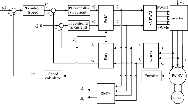
Fig. 1 Block diagram of a PMSM vector control with SMO
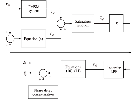
Fig. 2 Block diagram of conventional SMO with saturation function
3.2 Proposed adaptive observer gain for SMO
The SMO is known as a high gain observer which has appropriate behaviors in disturbance rejection. In the conventional SMO, a high constant gain observer is used in its estimation algorithm. The noise and chattering problem caused by the switching block are magnified because of the high gain usage. However, the estimation results will be deteriorated if the gain of the observer is too small. Hence, an appropriate gain is desirable for the observer to perform precise estimation and to suppress the chattering problem.
In this work, an adaptive observer gain is proposed to overcome the problem of the constant gain observer for the SMO. The adaptive observer gain is designed through the Lyapunov function. The sliding surface described in Eq. (7) is defined as the estimation error of the stator current. When the condition  is satisfied, the sliding mode exists, and this implies that S��0 for t����,
  and
and  The Lyapunov function candidate is defined in Eq. (12) to design the adaptive observer gain and to set up the stability condition of the SMO.
 (12)
(12)
From the Lyapunov stability theorem, the system is asymptotically stable when  hence:
 (13)
(13)
Equation (14) is obtained by substituting Eq. (6) into Eq. (13).

 (14)
(14)
The Lyapunov stability condition is satisfied when:
 (15)
(15)
where K is the observer gain. The condition of K represented in Eq. (15) is used in the conventional SMO as a constant value. Maximum value of the back-EMF produced at the maximum speed rotation of the motor is applied on the conventional SMO. Since the PMSM motor is generally used as a servo motor, variable speed operation is preferred for its control. When the motor operated in the low-speed area, the chattering problem will be magnified maximally by the constant observer gain. Hence, the observer gain should be regulated appropriately based on the speed reference. In here, the adaptive observer gain based on the speed reference is taking a place in the SMO. The design of the adaptive observer gain in this paper is achieved by a simple addition from the Lyapunov stability method that had already done until Eq. (15). The adaptive observer gain shown in Eq. (16) is designed based on Eq. (15) and Eq. (2). The back-EMF, which described in Eq. (2), will reach the maximum value when the values of sin��r and cos��r are equal to 1.
 (16)
(16)
where  is speed reference. With this adaptive method, the observer gain can adjust to the actual back-EMF so that the gain is appropriate to estimate the back-EMF precisely and able to suppress the chattering problem.
3.3 Proposed cascade LPF with variable cut-off frequency and variable phase delay compensation
In the conventional SMO system, a first-order LPF was used to decrease the chattering problem caused by the discontinuous function and high observer gain. However, the usage of the LPF is not enough to attenuate the chattering problem. Moreover, it induces changeable phase delay on the estimated back-EMF that leads to error in estimating the rotor position. The rotor angular position, which shown in Eq. (10), is calculated by using the arc-tangent mathematical operation from the estimated back-EMF. This method is considerably influenced by the existence of the noises and harmonics on the estimated back-EMF. The severe condition is the estimation at the back-EMF zero crossing. Subsequently, the estimated rotor angular position will be deteriorated if the estimated back-EMF includes noises and harmonics [35-37]. Those problems occurred because the cut-off frequency of the LPF is set to a constant value, which its value is decided to cover the maximum frequency of the PMSM. Hence, appropriate cut-off frequency based on the speed reference is needed in order to properly filtering the chattering problem and to accurately estimate the rotor flux position information for the variable control of PMSM applications.
A cascade LPF with variable cut-off frequency is proposed in this work to strengthen the filtering capability instead of the first-order LPF. The attenuation performance for suppressing the chattering problem will increase twice higher by using the cascade LPF. However, the usage of this filter causes a longer time delay in estimating the position of the rotor flux. The variable phase delay compensation method is used to counterbalance the phase delay (����) precisely based on the given speed reference. Equations (17) and (18) describe the proposed cascade LPF and its phase delay equation.
 (17)
(17)
 (18)
(18)
The cut-off frequency of the proposed cascade LPF and its phase delay are varied based on the given speed reference. Decision of the cut-off frequency fc is described as follows:
 (19)
(19)
 (20)
(20)
where n and P represent the speed in rpm and poles of the PMSM respectively. The angular frequency ��c of the proposed second order cascade LPF with advanced phase delay compensation method can be obtained by substituting Eq.(20) into Eq.(19).
 (21)
(21)
Figure 3 shows the block diagram of the proposed SMO.
4 Experimental set-up
The experimental set-up (Fig. 4) is based on surface mounted PMSM drive consisting of the following components.
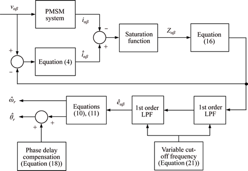
Fig. 3 Block diagram of proposed SMO with saturation function
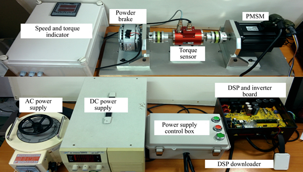
Fig. 4 Experimental setup
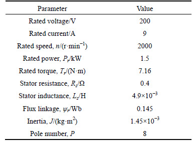
A three-phase PMSM model EMG 15-APA22 with parameters listed in Table 1; A 32-bit fixed DSP development system model TMS320f28035; A three- phase voltage source inverter (VSI) with maximum DC link voltage 450 V, rated current 14 A, rated power 1.5 kW and working at PWM frequencies up to 20 kHz.
The PMSM has no saliency as listed in Table 1, and it is equipped with 2000-line quadrature encoder that has been used here for comparing the estimated speed with the actual one. The experimental system is provided also with a suitable graphical user interface to manage the reference variable of the drive and to monitor responses of the drive at the same time. The sampling period of the control system was set at 100 ��s. The carrier frequency of the inverter was set at 10 kHz and the switching dead time was set at 2 ��s. Two kinds of experiment, conventional SMO estimation method and proposed SMO estimation method, were done in this research. The conventional SMO parameters were set as 105 for the observer gain K and 133.33 kHz for the cut-off frequency fc of the LPF and its phase delay compensation. The experimental results were compared directly side by side in order to verify the improvement of the proposed SMO estimation method. Both of the SMO estimation methods were tested under no load and loaded condition to check the estimation performance.
Table 1 Nominal parameters of PMSM
5 Experimental results and analysis
The proposed SMO estimation method has been tested experimentally on the test rig that is described. The experiment of the proposed SMO estimation method has been performed and compared with the conventional SMO estimation method to verify the effectiveness at low and high-speed operation. The mean square of the speed estimation error is calculated by using Eq. (22) to define the estimated error with regards to the actual speed response.
 (22)
(22)
5.1 Experiments with no load
In this experiment, the conventional SMO estimation method and proposed SMO estimation method were given the same speed profile, starts from 1600 r��min-1 and then reduces to 40 r/min, without load added into the system. These experiments were done in order to validate the proposed SMO estimation behavior and performance under no-load condition compared to the conventional SMO estimation method.
Figures 5(a) and (b) show the speed response and its estimation error of the conventional SMO estimation method without load condition. From these results, it can be seen that the conventional SMO estimation method was able to give a good tracking performance of the estimated speed at 1600 r/min with the maximum steady-state error as 0.5%. However, the tracking performance became deteriorated when the speed reference decreased into 40 r/min. The estimated speed result of the conventional SMO estimation method was failed to track the actual speed precisely. The big fluctuation was happened in the estimated speed because of the chattering phenomena. The maximum steady-state error of the estimated speed at 40 r/min was 82.5%. The total mean square of the speed estimation error was 130.32 r2/m2.
On the other hand, the experimental results of the proposed SMO estimation method, shown in Figs. 5(c) and (d), give a better results compared to the conventional method results. Figure 5(c) shows the speed response of the proposed SMO estimation method. The proposed SMO estimation method was able to provide a precise tracking performance of the estimated speed in all speed range. The maximum steady-state error at 1600 r/min was 0.25% and 10% at 40 r/min. The chattering phenomena was successfully decreased by using the proposed SMO method. The total mean square of the speed estimation error was 5.16 r2/m2. The proposed SMO estimation method was made a significant improvement in the speed estimation performance compared to the conventional SMO method.
Figures 6(a) and (b) shows the rotor angular position response and its estimation error of the conventional SMO method at 1600 r/min. The estimated rotor angular position was confirmed to have a big phase shift compared to the actual value. This big phase shift happens because it was not correctly compensated in the conventional SMO method. The constant value cut-off frequency of the LPF and its phase delay compensation was not appropriate to counterbalance the phase shift. Furthermore, major chattering phenomena happened as it can be seen in Fig. 6(a) of the estimated rotor angular position. Figure 6(b) shows the estimation error of the rotor angular position with 2.3 rad as the error in the steady-state condition. According to the latest research on the model-based estimation method, this big error was not a big problem for the sensorless control of a PMSM to work in the medium until the high-speed operation. However, the control performance was confirmed to have a low precision control on a position tracking performance.
Figures 6(c) and (d) shows the rotor angular position response and its estimation error of the proposed SMO method at 1600 r/min. These results ensured that the proposed SMO method gives a precise tracking performance of the estimated rotor angular position. The phase shift that happened in the estimated value was almost null. From Fig. 6(d), the estimation error was below 0.1 rad. The proposed SMO method that equipped with the proposed cascade LPF was successfully attenuate the filtering capability. The chattering phenomena on the estimated rotor angular position were decreased effectively by using the proposed cascade LPF with a variable cut-off frequency. Moreover, the proposed variable phase delay compensation was able to counterbalance the phase shift on the estimated rotor angular position precisely.
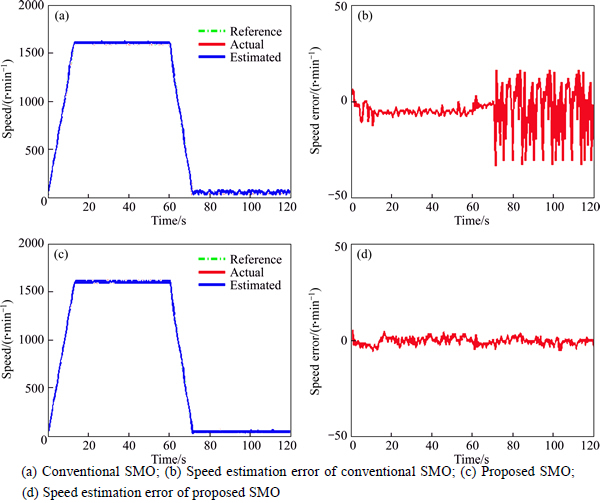
Fig. 5 Speed response with no load:
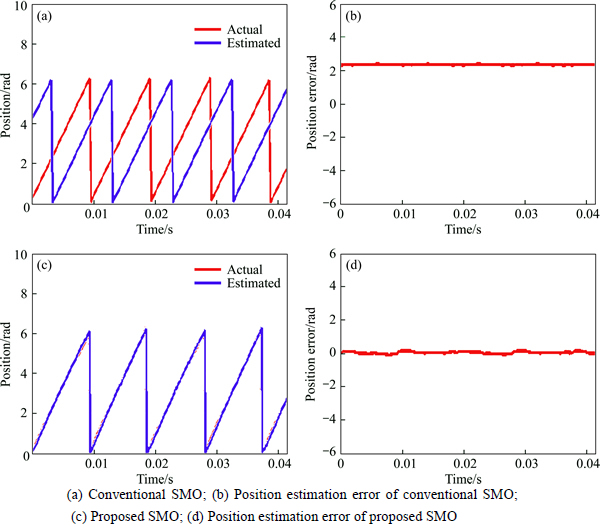
Fig. 6 Position response at 1600 r/min with no load:
Figures 7(a) and (b) shows the rotor angular position response and its estimation error of the conventional SMO method in the low-speed set at 40 r/min. From these experiments, the phase shift and the estimation error at 40 r/min were bigger than the results of the conventional SMO method at 1600 r/min. The electrical frequency of the PMSM was smaller than the cut-off frequency of the LPF and the phase delay compensation when the motor works at the low-speed. Hence, the LPF was not effectively attenuated the chattering phenomena and the phase shift in the estimated rotor angular position became bigger because of incorrect phase delay compensation. From Fig. 7(b), the error estimation of the rotor angular position was within 3 rad on the steady-state. Based on these experimental results, this is why the conventional SMO method was only preferred for the medium to high-speed operation. Precise position estimation is considerably important for the sensorless PMSM control to be able to work in a very low-speed operation.
Figures 7(c) and (d) show the rotor angular position response and its estimation error of the proposed SMO method at 40 r/min. From the experimental results, the estimated rotor angular position of the proposed SMO method in the low-speed operation was giving correct tracking performance as precise as the performance at the high-speed operation. From Fig. 7(d), the estimation error was within 0.1 rad. This error estimation value was same with the error that happened in the high-speed operation. This result means that the proposed cascade LPF with variable cut-off frequency and variable phase delay compensation were successfully suppressed the chattering phenomena and compensated the phase shift in the entire speed operation. The value of the cut-off frequency was appropriately regulated by the proposed SMO method according to the speed of the motor.
Figure 8 depicts the back-EMF estimation waveforms of the conventional SMO method and the proposed SMO method in the high-speed and the low-speed operation. The back-EMF estimation of the conventional SMO suffers from chattering phenomena on its waveform as shown in Figs. 8(a) and (b). In the SMO, the chattering phenomena was firstly appeared in the back-EMF estimation because of the discontinuous function usage. The conventional SMO method used the first-order LPF to filter the chattering phenomena. However, the attenuation rate of this filter is not enough to suppress the chattering. Moreover, the chattering phenomena was magnified maximally by the constant observer gain that used in the conventional SMO method. The chattering phenomena was even bigger when the PMSM works in the low-speed as shown in Fig. 8(b). This chattering that happened on the back-EMF estimation was made the estimated rotor angular position deteriorated especially in the very low-speed operation.
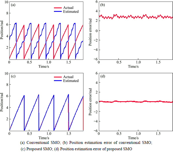
Fig. 7 Position response at 40 r/min with no load:
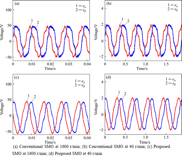
Fig. 8 Back-EMF waveform with no load:
On the other hand, the back-EMF estimation of the proposed SMO method was giving a better waveform in any speed operation as shown in Figs. 8(c) and (d). The chattering problem caused by the discontinuous function was successfully reduced by the usage of the proposed adaptive observer gain resulting in a smooth back-EMF estimation waveform. The proposed adaptive observer gain was regulated according to the speed of the PMSM. Hence, the chattering phenomena can be suppressed especially when the PMSM works in the very low-speed. The rotor angular position and speed can be estimated correctly when the chattering decrease minimally. Moreover, the proposed cascade filter was successfully decreased the chattering that happened in the estimated back-EMF. The proposed cascade LPF had better suppression property than the first-order LPF. The cut-off frequency of the proposed cascade LPF was varied according to the PMSM speed. Hence, the filter was effectively filtered the chattering phenomena in accordance with the electrical frequency of the PMSM.
5.2 Experiments with load
In this experiment, the conventional SMO estimation method and proposed SMO estimation method were tested in two separates speed reference, high and low-speed reference, under a loaded condition. 6 N��m load torque reference (85% from the rated torque) has been given to both estimation methods. These experiments were done in order to verify the proposed SMO estimation behavior and performance under a loaded condition compared to the conventional SMO estimation method.
Figures 9 to 11 show the experimental results comparison of the conventional SMO method and proposed SMO method at high-speed operation set as 1600 r��min-.1. Figure 9 shows the speed response for both of the estimation methods. From this result, it can be seen that both of the estimation methods were giving a good speed tracking performance at high-speed operation under a loaded condition. However, the maximum steady-state error and the total mean square of the speed estimation error of the conventional SMO method were bigger than the proposed SMO method. The maximum steady-state error in a loaded state and the total mean square of the speed estimation error were 0.25% and 66.49 r2/min2 by using the conventional SMO method. Whereas using the proposed SMO method was 0.2% for its maximum steady-state error in a loaded state, and 9.15 r2/min2 for its total mean squared of the speed estimation error. It is cleared that the proposed SMO method gives a better speed tracking performance.
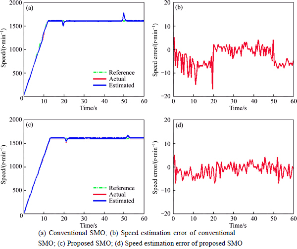
Fig. 9 Speed response at 1600 r/min with 6 N��m load torque:
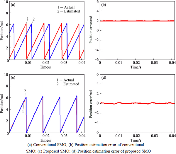
Fig. 10 Position response at 1600 r/min with 6 N��m load torque:

Fig. 11 Back-EMF waveform at 1600 r/min with 6 N��m load torque:
Figure 10 shows the rotor angular position response both of the estimation methods of the conventional SMO method and proposed SMO method at 1600 r/min under a loaded state. It was confirmed that the rotor angular position estimation result of the proposed SMO method was giving a better tracking performance than the conventional SMO method result. The estimation error of the estimated rotor angular position on the steady-state was 0.1 rad for the proposed SMO method while estimation error of the conventional SMO method was 2.1 rad. Figure 11 shows the back-EMF estimation waveform of the conventional SMO method and the proposed method at 1600 r/min in a loaded condition. The estimated back-EMF waveform for both of the estimation methods under a loaded state was better compared to the results without load. In fact, the existence of the load to the system has a positive effect on the back-EMF estimation waveform that results in good rotor angular position estimation. This positive effect came from bigger value of the Iq current in the load state than in no load state.
Figures 12 to 14 show the experimental results comparison of the conventional SMO method and proposed SMO method at low-speed operation set as 40 rpm. Figure 12 shows the speed response for both of the estimation methods. There was clear distinction between the conventional SMO method and the proposed method speed response. The estimated speed response of the proposed SMO method provides a better tracking performance than the conventional SMO method. The maximum steady-state error in a loaded state and the total mean square of the speed estimation error were 32.5% and 283.43 r2/min2 by using the conventional SMO method. Whereas using the proposed SMO method was 10% for its maximum steady-state error in a loaded state, and 6.45 r2/min2 for its total mean squared of the speed estimation error.
Figure 13 represents the rotor angular position response of the conventional SMO method and proposed SMO method at 40 r��min-1 under a loaded state. From the experimental results, it can be seen that the estimated rotor angular position of the proposed SMO method provides a better tracking performance than the conventional SMO method result. The estimation error of the estimated rotor angular position on the steady-state was 0.1 rad for the proposed SMO method while the estimation error of the conventional SMO method was 2.3 rad. Figure 14 shows the back-EMF estimation waveform of the conventional SMO method and the proposed method at 40 r��min-1 under a loaded condition. The chattering phenomena was still affecting the estimations value much, even though the load addition to the PMSM system was made a better tracking error of the conventional SMO method. On the other hand, the proposed SMO method was able to give a better estimation performance in a loaded or without load state. The proposed adaptive observer gain was able to regulate the chattering phenomena even in the very low-speed. Furthermore, the proposed cascade LPF with variable cut-off frequency and variable phase delay compensation were able to suppress the chattering effectively and capable to counterbalance the phase shift precisely in the very low-speed.
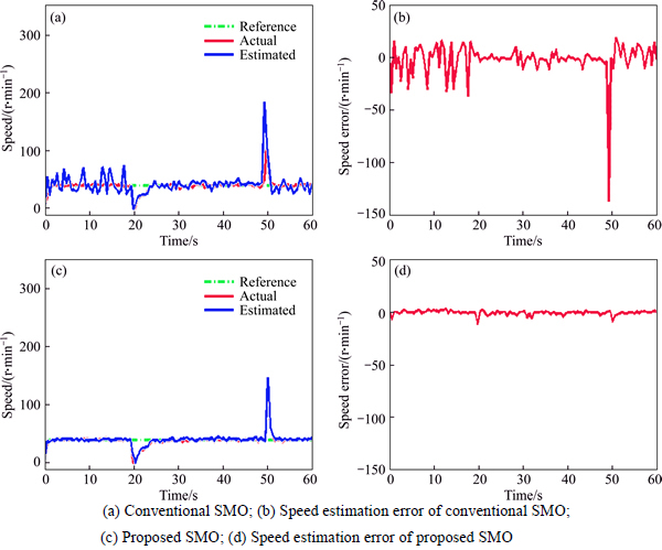
Fig. 12 Speed response at 40 r/min with 6 N��m load torque:
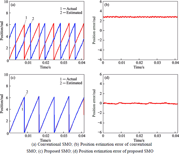
Fig. 13 Position response at 40 r/min with 6 N��m load torque:
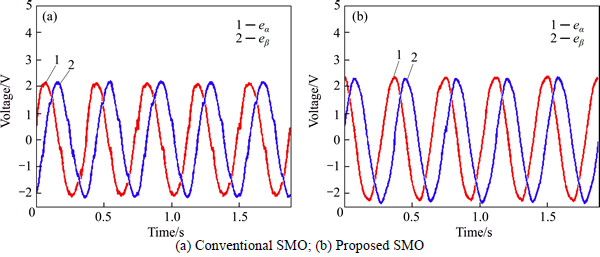
Fig. 14 Back-EMF waveform at 40 r/min with 6 N��m load torque:
6 Conclusions
This work proposes a new strategy to improve the rotor angular position estimation performance of the SMO for a PMSM. The adaptive observer gain and the cascade LPF with variable cut-off frequency are proposed to escalate the rotor angular position estimation performance and to expand the operation range of the SMO. In addition, the variable phase delay compensation method is suggested to counterbalance the phase shift caused by the cascade LPF. The experimental results indicate that the speed and rotor angular position are correctly estimated by the proposed SMO. The adaptive observer gain effectively suppress the chattering problem that happened in the back-EMF estimation. The proposed cascade LPF reduced the chattering phenomena and the variable phase delay compensation method counterbalance the phase delay of the estimated rotor angular position effectively. The experimental results imply that the proposed SMO gives a precise rotor angular position estimation in the entire speed range. Moreover, the estimation performance was significantly improved especially in the low-speed operation by applying the proposed SMO.
References
[1] CHI W C, CHENG M Y. Implementation of a sliding-mode-based position sensorless drive for high-speed micro permanent-magnet synchronous motors [J]. ISA Trans, 2014, 53(2): 444-453.
[2] ZHANG B, PI Y, LUO Y. Enhanced robust fractional order proportional-plus-integral controller based on neural network for velocity control of permanent magnet synchronous motor [J]. ISA Trans, 2012, 52(4): 510�C516.
[3] CHI S, ZHANG Z, XU L. Sliding-mode sensorless control of direct-drive PM synchronous motors for washing machine applications [J]. IEEE Trans Ind Appl, 2009, 45(2): 582�C590.
[4] HOLTZ J, JUNTAO J. Sensorless vector control of induction motors at very low speed using a nonlinear inverter model and parameter identification [J]. IEEE Trans Ind Appl, 2002, 38(4): 1087�C1095.
[5] ACCETTA A, CIRRINCIONE M, PUCCI M. TLS EXIN based neural sensorless control of a high dynamic PMSM [J]. Control Eng Pract., 2012, 20(7): 725�C732.
[6] HOLTZ J, MODEL A S. Sensorless control of induction machines�� With or without signal injection [J]. IEEE Transactions on Industrial Electronics, 2006, 53(1): 7�C30.
[7] ZHU Z Q, GONG L M. Investigation of effectiveness of sensorless operation in carrier-signal-injection-based sensorless-control methods [J]. IEEE Trans Ind Electron, 2011, 58(8): 3431-3439.
[8] CORLEY M J, LORENZ R D. Rotor position and velocity estimation for a salient-pole permanent magnet synchronous machine at standstill and high speeds [J]. Ind Appl IEEE Trans, 1998, 34(4): 784-789.
[9] JANSEN P L, LORENZ R D. Transducerless position and velocity estimation in induction and salient AC machines [J]. IEEE Trans Ind Appl, 1995, 31: 488-495.
[10] RACA D,  P, REIGOSA D D, BRIZ F, LORENZ R D. Carrier-signal selection for sensorless control of PM synchronous machines at zero and very low speeds [J]. IEEE Trans Ind Appl, 2010, 46(1): 167-178.
[11] CUPERTINO F, PELLEGRINO G, GIANGRANDE P, MEMBER S, SALVATORE L. Sensorless position control of permanent-magnet motors with pulsating current injection and compensation of motor end effects [J]. IEEE Trans Ind Appl, 2011, 47(3): 1371-1379.
[12] RAUTE R, CARUANA C, STAINES C S, CILIA J, SUMNER M, MEMBER S, ASHER G M. Analysis and compensation of inverter nonlinearity effect on a sensorless pmsm drive at very low and zero speed operation [J]. IEEE Trans Ind Electron, 2010, 57(12): 4065-4074.
[13] ROBEISCHL E, SCHROEDL M. Optimized INFORM measurement sequence for sensorless PM synchronous motor drives with respect to minimum current distortion [J]. IEEE Trans Ind Appl, 2004, 40(2): 591-598.
[14] HENWOOD N, MALAIZE J, PRALY L, CENTRE C. A robust nonlinear luenberger observer for the sensorless control of sm-pmsM: Rotor position and magnets flux estimation [C]// Conference on IEEE Industrial Electronics Society. Montreal: IEEE, 2012: 1625- 1630.
[15] BRANDSTETTER P, RECH P, SIMONIK P. Sensorless control of permanent magnet synchronous motor using luenberger observer [C]// PIERS Proceedings. Cambridge, USA: PIERS. 2010: 424-428.
[16] KHLAIEF A, BOUSSAK M,  A. A MRAS-based stator resistance and speed estimation for sensorless vector controlled IPMSM drive [J]. Electr Power Syst Res, 2014, 108: 1-15.
[17] RASHED M, MACCONNELL P F A, STRONACH A F, ACARNLEY P. Sensorless indirect-rotor-field-orientation speed control of a permanent-magnet synchronous motor with stator- resistance estimation [J]. IEEE Trans Ind Electron, 2007, 54(3): 1664-1675.
[18] ORLOWSKA-KOWALSKA T, DYBKOWSKI M, Stator-current- based MRAS estimator for a wide range speed-sensorless induction-motor drive [J]. IEEE Trans Ind Electron, 2010, 57(4): 1296-1308.
[19] XU D, ZHANG S, LIU J. Very-low speed control of PMSM based on EKF estimation with closed loop optimized parameters [J]. ISA Trans, 2013, 52(6): 835-843.
[20] SHEHATA E G. Speed sensorless torque control of an IPMSM drive with online stator resistance estimation using reduced order EKF [J]. Int J Electr Power Energy Syst, 2013, 47: 378-386.
[21] BENCHABANE F, TITAOUINE A, BENNIS O, YAHIA K, TAIBI D. Sensorless fuzzy sliding mode control for permanent magnet synchronous motor fed by AC/DC/AC converter [J]. Int J Syst Assur Eng Manag, 2012, 3(3): 221-229.
[22] AYDOGMUS O, S NTER S. Implementation of EKF based sensorless drive system using vector controlled PMSM fed by a matrix converter [J]. Int J Electr Power Energy Syst, 2012, 43(1): 736-743.
[23] BOLOGNANI S, OBOE R, ZIGLIOTTO M. Sensorless full-digital PMSM drive with EKF estimation of speed and rotor position [J]. IEEE Trans Ind Electron, 1999, 46(1): 184-191.
[24] BOLOGNANI S, TUBIANA L, ZIGLIOTTO M. Extended Kalman filter tuning in sensorless PMSM drives [J]. IEEE Trans Ind Appl, 2003, 39(6): 1741-1747.
[25] UTKIN V, GULDNER J, SHI J. Sliding mode control in electromechanical Systems [M]. New York: CRC Press, 1999.
[26] HAN Y, CHOI J, KIM Y. Sensorless PMSM drive with a sliding mode control based adaptive speed and stator resistance estimator [J]. IEEE Trans. Magn., 2000, 36(5): 3588-3591.
[27] LEE H, LEE J. Design of iterative sliding mode observer for sensorless PMSM control [J]. IEEE Trans Control Syst Technol, 2013, 21(4): 1394-1399.
[28] ZHAO Y, QIAO W, WU L. Compensation algorithms for sliding mode observers in sensorless control of IPMSMs compensation algorithms for sliding mode observers in sensorless control of IPMSMs [C]// 2012 IEEE International, Electrie vehicle lonferenmce, 2012, Greenville, USA: IEEE, Doi: 10.1109/IEVC.2012.6183241.
[29] KUNG Y S, NGUYEN V Q, HUANG C C, HUANG L C, Simulink/modelSim co-simulation of sensorless PMSM speed controller [C]// IEEE Symposium on Industrial Electronics and Applications Taipei, China: IEEE, 2011: 24�C29.
[30] JUNG Y, KIM M. Sliding mode observer for sensorless control of IPMSM drives [J]. J Power Electron., 2009, 9(1): 117-123.
[31] ZHENG J, FENG Y, YU X. Hybrid terminal sliding mode observer design method for permanent magnet synchronous motor control system [C]// 2008 Int Work Var Struct Syst, New York: IEEE, 2008: 106-111.
[32] PAPONPEN K. Speed sensorless control of pmsm using an improved sliding mode observer with sigmoid function [J]. ECTI Trans. Electr. Eng Electron Commun, 2007, 5(1): 51-55.
[33] KIM H, SON J, LEE J, MEMBER S. A high-speed sliding-mode observer for the sensorless speed control of a PMSM [J]. IEEE Transactioons on Industrial Electronics, 2011, 58(9): 4069�C4077.
[34] QIAO Z, SHI T, WANG Y, YAN Y, XIA C, HE X. New sliding-mode observer for position sensorless control of permanent-magnet synchronous motor [J]. IEEE Trans Ind Electron, 2013, 60(2): 710-719.
[35] REN J J, LIU Y C, WANG N, LIU S Y. Sensorless control of ship propulsion interior permanent magnet synchronous motor based on a new sliding mode observer [J]. ISA Trans on Industrial Electronics, 2014: 1-12.
[36] GENDUSO F, MICELI R, RANDO C, GALLUZZO G R. Back-EMF sensorless control algorithm for high dynamics performances PMSM [J]. IEEE Trans Ind Appl, 2009, 57: 1-9.
[37] JANG J, SUL S, HA J. Sensorless drive of surface-mounted permanent-magnet motor by high-frequency signal injection based on magnetic saliency [J]. IEEE Trans Ind Appl, 2003, 39(4): 1031-1039.
(Edited by DENG L��-xiang)
Foundation item: Project(2012(PS-2012-090)) supported by the Pukyong National University Research Abroad Fund, Korea
Received date: 2015-05-04; Accepted date: 2015-11-04
Corresponding author: Seok-Kwon Jeong, PhD, Professor; Tel: +82-51-6296181; E-mail: skjeong@pknu.ac.kr

