J. Cent. South Univ. (2017) 24: 708-719
DOI: 10.1007/s11771-017-3472-2

Determination of isolation layer thickness for undersea mine based on differential cubature solution to irregular Mindlin plate
PENG Kang(����)1, 2, 3, LIU Zhao-peng(������)1, 3, ZHANG Yong-liang(������)4,
FAN Xiang(����)5, CHEN Qin-fa(���췢)6
1. State Key Laboratory of Coal Mine Disaster Dynamics and Control, Chongqing University,
Chongqing 400044, China;
2. State Key Laboratory of Resources and Safe Mining (CUMT), Xuzhou 221116, China;
3. College of Resources and Environmental Science, Chongqing University, Chongqing 400030, China;
4. Automotive School, Qingdao Technological University, Qingdao, Shandong 266520, China;
5. School of Highway, Chang��an University, Xi��an 710064, China;
6. College of Resources and Metallurgy, Guangxi University, Nanning 530004, China
 Central South University Press and Springer-Verlag Berlin Heidelberg 2017
Abstract: The differential cubature solution to the problem of a Mindlin plate lying on the Winkler foundation with two simply supported edges and two clamped edges was derived. Discrete numerical technology and shape functions were used to ensure that the solution is suitable to irregular shaped plates. Then, the mechanical model and the solution were employed to model the protection layer that isolates the mining stopes from sea water in Sanshandao gold mine, which is the first subsea mine of China. Furthermore, thickness optimizations for the protection layers above each stope were conducted based on the maximum principle stress criterion, and the linear relations between the best protection layer thickness and the stope area under different safety factors were regressed to guide the isolation design. The method presented in this work provides a practical way to quickly design the isolation layer thickness in subsea mining.
Key words: subsea mine; irregular Mindlin plate; differential cubature method; isolation layer; protection layer; thickness optimization
1 Introduction
With the depletion of mineral resources in near surface ground, mining exploitation in challenging environments such as at great depth and under sea water has become an inevitable trend all over the world [1]. The determination of the minimum required thickness of isolation layer (or called rock cover or crown pillar) is an extraordinary issue to keep the sea water out from mining excavations for subsea mining. Unfortunately, to our best knowledge, the reported research on the minimum thickness of crown pillar or rock cover is still relatively scarce. Series of related experiences could be found in the constructions of subsea tunnel, such as the Norwegian subsea tunnels [2, 3] and the Ningbo Xiangshan Harbour subsea tunnel [4]. However, since the size of mining stope is usually larger than that of tunnels and the blasting induced disturbance in subsea mine is more severe than that in subsea tunnel, previous experiences cannot be directly applied to subsea mines [1]. Furthermore, the irregular shape of subsea mining stope also increases the difficulty in determining the minimum thickness of crown pillar. Therefore, the existing methods for subsea rock cover design, such as engineering analogy method, are incapable for subsea mining, and numerical modelling of the whole studied area seems to be the only way to solve the problem. With the help of the FLAC3D software, LI et al [1] successfully determined the thickness of the crown pillar of Sanshandao mine. Nevertheless, large scale numerical simulations can only assess several predetermined thicknesses and select the best one from them, and they are not able to optimize the thickness from a continuous interval.
The purpose of this work is to provide a continuous method to optimize the isolation layer thickness from a given interval, through utilizing the plate model. For the past few years, various plate models were widely applied in diverse fields. For example, OU et al [5] studied the vibration of stiffened plate under the condition of general elastic boundaries; LI et al [6] put forward an exact series solution for the transverse vibration of rectangular plates with general elastic boundary supports. CIVALEK [7] studied thin rectangular plates on Winkler�CPasternak elastic foundations by DSC�CHDQ methods. General speaking, irregular plates are more common in practical applications. Furthermore, the arbitrary shape of plate always increases the solving difficulty, and Irregular plates have been deeply studied by many researchers. For example, CATANIA and SORRENTINO [8] gave the spectral model of vibrating plates with general shape and general boundary conditions; CHEUNG et al [9] put forward the spline finite strip method for vibration and static analysis of plate of general shape; SHI et al [10] analyzed the free vibration of arbitrary shaped plates by boundary knot method. Other studies on the plate structure can also be referred to Refs. [11-14]. In this work, the isolation layer is modelled as thick plate to optimize the isolation layer thickness.
2 Mindlin plate theory and its solution by differential cubature method
2.1 Mindlin plate theory
As fundamental parts in engineering, plates play important roles in the entire structure. There exists a variety of mechanical models for plates, among which the thin plate theory with Kirchhoff hypothesis is the most classical one. With respect to the plate with relatively large thickness, because the Kirchhoff hypothesis only accounts for the deflection freedom and ignores the shear deformation, the error of the theory cannot be neglected [15]. REISSNER [16, 17] proposed the straight assumption to replace the Kirchhoff assumption, i.e., the line that perpendiculars to the middle surface keeps straight after the deformation, thus it is essential to consider the impact of shear strains on the deformation of the plate. Furthermore, Mindlin improved the model proposed by REISSNER and suggested the Mindlin plate theory [18], which is employed by subsequent researches [19-21]. The equilibrium equations of Mindlin plates are given by Eq. (1), and the relations between the internal forces and the displacements are given by Eq. (2).
 (1a)
(1a)
 (1b)
(1b)
 (1c)
(1c)
 (2a)
(2a)
 (2b)
(2b)
 (2c)
(2c)
 (2d)
(2d)
 (2e)
(2e)
where Mx and My are the bending moments; Mxy and Myx are the twisting moments; Qx and Qy are the shear resultants; ��x and ��y are the rotations of the normal about x-axis and y-axis, respectively; w is the transverse deflection; E is the elastic modulus; �� is the Poisson ratio;
h is the thickness of the plate;  is the bending rigidity; G is the shear modulus; and q is the load on the plate.
 (3)
(3)
By substituting Eq. (2) into Eq. (1), three governing equations are obtained [22, 23], shown as Eq. (3); where  represents Laplace��s two-dimensional operator.
2.2 Differential cubature method
The governing Eq. (3) in Mindlin plates are high order partial differential equations. Among these solutions, the approach that transforms the Cartesian coordinates into natural coordinates when the plate is irregular appeals to many scholars [12, 15]. However, for high order differential equations with multiple dimensions, this technique is very complex to implement both in the process of derivation and calculation. To overcome this issue, the differential cubature (hereafter DCM) method was proposed [24].
DCM uses the linear combination of a function��s values at several points in the concerned range to replace the linear operations acting on the function [23, 24], such as the partial differential operation. In a 2-D situation, the theory of DCM can be briefly written as
 (4)
(4)
where R is one or a combine of several differential operators with any order; cij are cubature coefficients. Owing to the fact that the determination of cij is only decided by R, one can calculate them by assuming f(x, y) to be a series of orthogonal polynomials as follows:

Rewrite the govern Eq. (3) as follows:
 (5)
(5)
By assuming 


 and
and  , Eq. (5) can also be written as
 (6)
(6)
where  ,
, 

Using the relation of Eq. (4), Eq. (6) is transformed by the following equations for ith calculation point in the solution domain:

 (7a)
(7a)


(7b)

 (7c)
(7c)
As for the calculation points on the clamped boundaries and the simple-supported boundaries, ith, for example, corresponding equations of Eq. (7) should be replaced by Eqs. (8) and (9), respectively.
 (8a)
(8a)
 (8b)
(8b)
 (8c)
(8c)
(9a)


 (9b)
(9b)
(9c)
2.3 Discrete numerical technology and its implementation
Once the calculation points are determined, one can easily solve the problem by solving the linear system of Eqs. (7), (8) and (9). Therefore, the focus comes to how to determine the irregular calculation point grid in an automatic way. Here, we give an automatic sampling technique to determine the point grid that is similar to Ref. [23] with the help of shape functions, as shown in Fig. 1. First, a regular point grid is pre-determined in the natural coordinate system. Then, with the relationship Eq. (10), i.e., the shape functions, the corresponding irregular point grid in the Cartesian coordinates can be obtained.
 (10)
(10)
where xi and yi are the coordinates of the four corners of the irregular plate in the Cartesian system, 


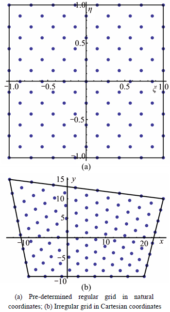
Fig. 1 Automatic mapping technique for discrete calculation point grid:
A completely automatic program, which is called ��Differential cubature for Mindlin plate (DCFMP)��, is designed using the Mathematica platform to realize the calculation procedure mentioned above. This program is not only suitable for the SCSC boundaries, but also able to solve the problems with SSSS or CCCC boundaries. To verify the accuracy and precision of DCFMP, series of numerical examples are given in Tables 1 and 2. The results obtained from the famous FEM program ABAQUS and extracted from Refs. [23, 25, 26] are also given in these two tables. Obviously, DCFMP gives accurate results both in the calculations of deflections and internal forces.
3 Application
3.1 Background
The Sanshandao gold mine locates at the northwestern Jiaodong Peninsula and is hosted on the north-northeast oriented, moderately southeast-dipping Sanshandao�CCangshang fault, which is poorly exposed and extends northeast to southwest into the Bohai Sea [27]. The studied area is under the border between the land and the ocean [28]. Half of the deposit is undersea, and the remainder is under land with numerous large water bodies. The estuary of the Wang River is northeast of the mine. This complex environmental background has led to diversification of water sources of the mine (Fig. 2). Therefore, the isolation layer isolating the water and the deposit is an extremely important structure for the mining operation.
The plan view of the Sanshandao ore isolation layer is also shown in Fig. 2. The rock isolation layer is divided into 18 subparts (numbered as 1#-18#) by the barrier pillars in the studied area. The shapes of the 18 subparts are close to irregular quadrangles with length 50 m, width 11.6-32.39 m, and area 580-1620 m2. In the Xinli zone of the Sanshandao gold mine, the country rock of the mine includes metagabbro, monzogranite, and cataclastic rocks. The cut-and-fill stoping method is used for ore extraction and ground control. The height of one mining stope is 40 m, and the interval between two barrier pillars is 100 m. The square panel pillar has a cross section of 5 m��5 m. Spacing between adjacent panel pillars is 15 m in each direction.
3.2 Protection layer model based on Mindlin theory
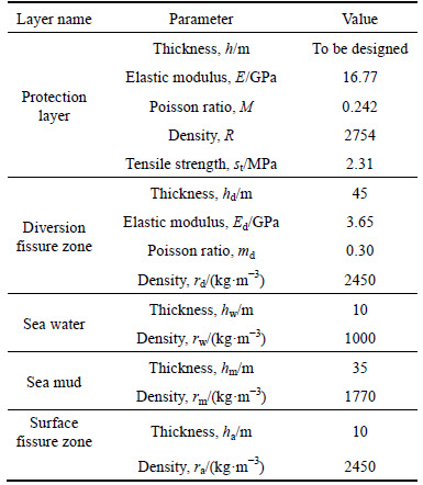
The rock layer that isolates sea water and mining stopes, from top to bottom, consists of surface fissure zone, protection layer and diversion fissure zone, see Fig. 3. The physical and mechanical properties of the isolation layer are shown in Table 3. While the thicknesses of the surface fissure zone and diversion fissure zone can be determined by experience or observation methods, the thickness of protection layer should be estimated by mechanical model, which is the main task of this work. According to the loading condition, the protection layer can be abstracted into a mechanical model given by Fig. 3.
Table 1 Comparison of results obtained from DCFMP and other programs (CCCC-boundary)
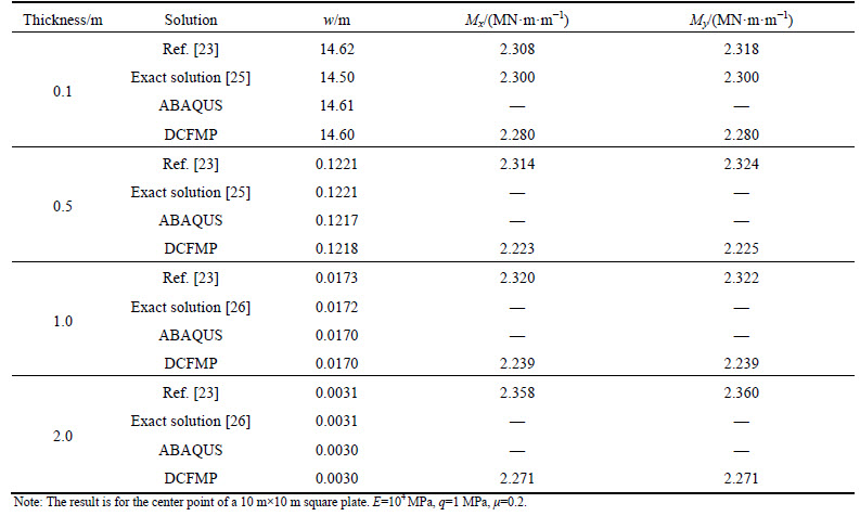
Table 2 Comparison of result obtained from DCFMP and other programs (SSSS-boundary)
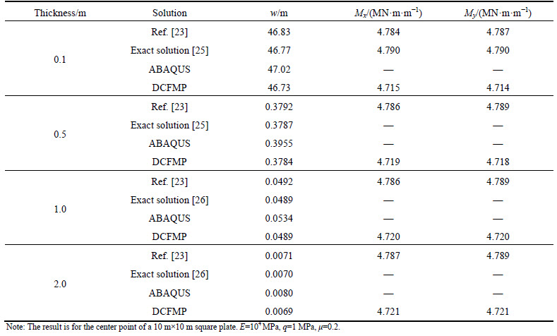
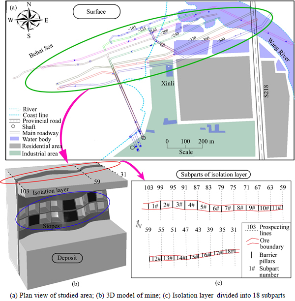
Fig. 2 Plan view of rock isolation layer of Sanshandao mine:
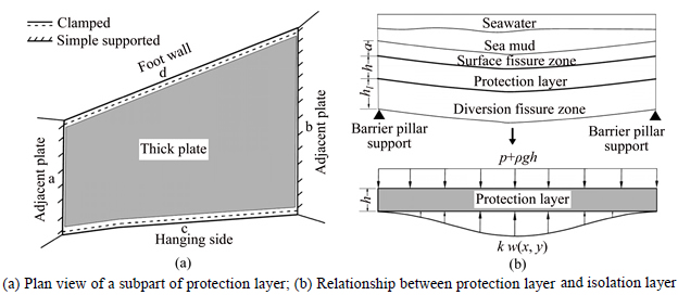
Fig. 3 Mechanical model of protection layer:
Table 3 Physical and mechanical parameters of isolation layer
The protection layer is modeled as an irregular thick plate, whose shape is close to quadrangles, see Fig. 3. Edges a and b can be considered as clamped since these two edges are the public edges between the plate and the adjacent plates. However, edges c and d can be regarded as simply supported edges because of the rotation support weakening caused by joints or discontinuities between different geological bodies, i.e., surrounding rock and ore. The loadings above the protection layer, i.e. seawater, sea mud and surface fissure zone, are simplified as uniform surface load p. The gravity of the protection layer is also loaded on the plate surface in a uniform manner. Additionally, the diversion fissure zone below is modeled as Winkler foundation so that can give support to the protection layer. Using Mindlin theory, the mechanical model of the protection layer is given by the governing equations and boundaries as Eqs. (11)-(13).
Governing equations:

(11a)
 (11b)
(11b)
 (11c)
(11c)
Clamped supported edges (a and b):
 (12a)
(12a)
 (12b)
(12b)
 (12c)
(12c)
Simple-supported edges (c and d):
(13a)
 (13b)
(13b)
(13c)
In the equations above, n and s represent normal and tangential directions respectively. k value is the only parameter of Winkler foundation. This simplification brings great convenience to researches, so that it is employed by many researchers [29-31]. On the other hand, this simplification may also bring corresponding error. Therefore, the determination of k is a key problem of this work. The determination method in Ref. [32] is employed in this study, and the detailed steps of the method is given as follows:
Step 1: Calculate the characteristic length using following equation:
 (14)
(14)
Step 2: Determine the nondimensionalized foundation parameter Knw according to the H/r value in Fig. 4.
Step 3: Determine the k value using the relationship given by following equation:
 (15)
(15)
where r is the characteristic length of the plate; H is the thickness of foundation (i.e., the thickness of diversion fissure zone in this study); Es is the elastic modulus of the diversion fissure zone; and Knw is the nondimensionalized foundation parameter.

Fig. 4 Relationship between nondimensionalized foundation parameter Knw and H/r [31]
3.3 Design of protection layer for sanshandao mine
3.3.1 Design method based on maximum principle stress criterion and safety factor
As the structure between the diversion fissure zone and the surface fissure zone that is for isolating the seawater, the protection layer is required to be intact and free from cracks. Therefore, the maximum principle stress criterion is employed to judge the failure of the rock of the protection layer, i.e., the maximum principle stress of a designed protection layer cannot exceed the tensile strength of the rock. Generally, the crack position of a bending plate is on the lower surface. Thus, one can ensure a design meets the requirements when the maximum principle stress on the lower surface is no more than the tensile strength. Assuming the stress components, ��x, ��y and ��xy, distribute linearly along the thickness of the plate, the five stress components on the plate can be written as
 (16a)
(16a)
 (16b)
(16b)
 (16c)
(16c)
 (16d)
(16d)
 (16e)
(16e)
The stress tensor on the lower surface (z=h/2) can be written as

The three-principle stress can be calculated from the above stress tensor. According to the maximum principle stress criterion,
 (17)
(17)
where ��t is the uniaxial tensile strength of the rock of the protection layer.
Introducing the safety factor s, the best protection layer thickness h* is determined by the following relation:
 (18)
(18)
3.3.2 Results
For the protection layer of each subpart, the maximum major principal stress under different protection layer thicknesses are calculated and shown in Figs. 5(a)-(c). With the thickness decreasing, the maximum major principal stress increases stably until the first peak. After that, the maximum major principal stress become unpredictable and unsteady with the continue decreasing of the thickness. Therefore, to ensure a reliable design, the stable part of the curves was considered to be the feasible range. Table 4 gives the best protection layer thicknesses calculated by Eq. (18) under different safety factors. In the case when the safety factor is 1.0 (i.e., the maximum major principal stress equals to the tensile strength), the best protection layer thicknesses are between 4.08 m to 11.9 m, and the average is 8.85 m. When the safety factor increases to 1.2, the best thicknesses increase by about 2.2 m to 7.14-14.84 m with average 11.1 m. However, with the safety factor continue growing, the best thicknesses of the protection layers increase by 1.2-1.3 m for every 0.2 safety factor increase.
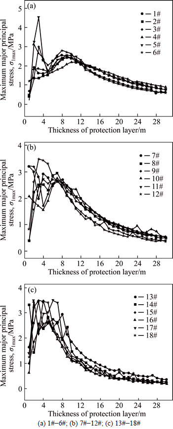
Fig. 5 Maximum major principal stress of protection layers of subparts:
The result of best protection layer thickness in Table 4 also shows a strong correlation between the thickness and the area of the subpart. Generally, a relative large area of subpart needs a relative thick protection layer. However, this rule is not always right, owing to the diversity of the subparts shape. To better understand this correlation, the linear regression of the area and the best thickness was made and shown in Fig. 6. The regression expressions are given by Eq. (19). For different safety factors, all of the correlation coefficients exceed 0.9, which indicates a strong correlation of the area and the thickness. The correlation allows designers to determine the best protection layer thickness both accurately and conveniently. For example, a designer may use Eq. (19) to obtain the best thickness of protection layer that is close to the result calculated by the complex procedure described above. This increases the practical value of this study.
In despite of the strong correction between the area and the best thickness, there is also an exception, i.e. 4# subpart under safety factor of 1.0 (see Fig. 6). Although the 4# subpart hold the largest area, it needs the least thickness for safety. This exception can be explained by the relative regular shape of the subpart. As shown in Table 4, the shape of the 4# subpart is very close to a rectangle, thus even the peak of the corresponding curve in Fig. 5(a) does not exceed the tensile strength. This exception demonstrates that a regular shape of the plate is conductive to improving the mechanical state.
s=1.0: h*=3.5470+0.00593A (19a)
s=1.2: h*=3.7145+0.00753A (19b)
s=1.4: h*=2.8459+0.00987A (19c)
Table 4 Best protection layer thicknesses under different safety factors
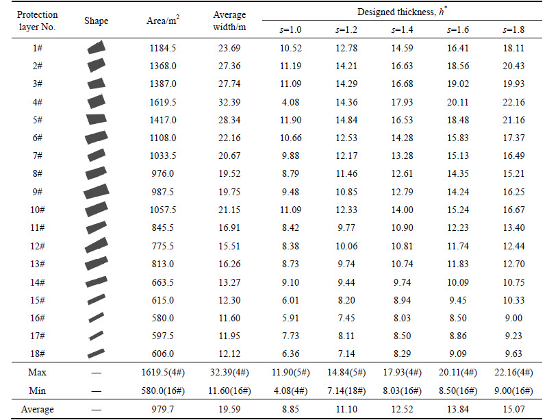

Fig. 6 Regression of best protection layer thickness and subpart area
s=1.6: h*=2.3526+0.01173A (19d)
s=1.8: h*=2.0155+0.01333A (19e)
The undersea mining requires a relative conservative safety factor due to the grave consequences of the mine disaster. Consulting the empirical value of a related study [33], a safety factor of 1.8 was used to determine the final projection layer thickness of Sanshandao mine, which is 22.16 m. Figure 7 displays the final deflection and the major principal stress of 1#-3# subparts. The distribution of the major principal the stress along the plate is consistent with that of the deflection, expect at corners of the plate. This can be explained by the boundary effect and the stress concentration at the corners.
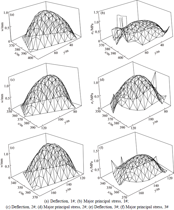
Fig. 7 Distribution of deflection (a, c, e) and the major principal stress (b, d, f):
4 Conclusions
1) A Winkler foundation based Mindlin plate model was derived. The established plate model fits the mechanical conditions of the protection layer of Sanshandao subsea gold mine, thus can be used in the thickness design of the protection layer.
2) Differential cubature method was used to solve the protection layer model and the corresponding program, DCFMP, was coded based on the Mathematica software to calculate automatically. To illustrate the accuracy of the differential cubature method, a comparison between the result of DCFMP and that of other programs was performed,
3) Based on the maximum tensile-stress criterion, the best protection layer thicknesses were estimated under different level of safety factors. Considering the practical condition, a thickness of 22.16 m with the safety factor of 1.8 was finally determined as the best protection layer thickness. Additionally, correlation analysis shows the strong correlation between the best protection thickness and the subpart area. The linear regression relations obtained by the correlation analysis enable analysts to design the best thickness of the protection layer much more simply and practically.
References
[1] LI X, LI D, LIU Z, ZHAO G, WANG W. Determination of the minimum thickness of crown pillar for safe exploitation of a subsea gold mine based on numerical modeling [J]. International Journal of Rock Mechanics & Mining Sciences, 2013, 57(1): 42�C56.
[2] NILSEN B, DAHLD T S. Stability and rock cover of hard rock subsea tunnels [J]. Tunnelling & Underground Space Technology, 1994, 9(2):151�C158.
[3] NILSEN B. The optimum rock cover for subsea tunnels. Rock mechanics contributions and challenges [C]// Proceeding of the 31st US Symposium on Rock Mechanics. Golden, BALKEMA A A, Rotterdam Colorado: ASME, 1990: 1005-1012.
[4] LI S C, LI S C, XU B S, WANG H P, DING W T. Study on determination method for minimum rock cover of subsea tunnel [J]. Chinese Journal of Rock Mechanics and Engineering, 2007, 26(11): 2289-2295.
[5] OU D Y, MAK C M, KONG P R. Free flexural vibration analysis of stiffened plates with general elastic boundary supports [J]. World Journal of Modelling and Simulation, 2012, 8(2): 96-102.
[6] LI W L, ZHANG X, DU J, LIU Z. An exact series solution for the transverse vibration of rectangular plates with general elastic boundary supports [J]. Journal of Sound and Vibration, 2009, 321(1): 254-269.
[7] CIVALEK  . Nonlinear analysis of thin rectangular plates on Winkler�CPasternak elastic foundations by DSC�CHDQ methods [J]. Applied Mathematical Modelling, 2007, 31(3): 606-624.
[8] CATANIA G, SORRENTINO S. Spectral modeling of vibrating plates with general shape and general boundary conditions [J]. Journal of Vibration and Control, 2012,18(18):1607�C1623.
[9] CHEUNG Y K, THAM L G, LI W Y. Free vibration and static analysis of general plate by spline finite strip [J]. Computational Mechanics, 1988, 3(3): 187-197.
[10] SHI J, CHEN W, WANG C. Free vibration analysis of arbitrary shaped plates by boundary knot method [J]. Acta Mechanica Solida Sinica, 2009, 22(4): 328-336.
[11] KANG S W, ATLURI S N. Free vibration analysis of arbitrarily shaped polygonal plates with simply supported edges using a sub-domain method [J]. Journal of Sound and Vibration, 2009, 327(3): 271-284.
[12] SAADATPOUR M M, AZHARI M. The Galerkin method for static analysis of simply supported plates of general shape [J]. Computers & Structures, 1998, 69(1): 1-9.
[13] KHOV H, LI W L, GIBSON R F. An accurate solution method for the static and dynamic deflections of orthotropic plates with general boundary conditions [J]. Composite Structures, 2009, 90(4): 474-481.
[14] QUINTANA M V, NALLIM L G. A general Ritz formulation for the free vibration analysis of thick trapezoidal and triangular laminated plates resting on elastic supports [J]. International Journal of Mechanical Sciences, 2013, 69: 1-9.
[15] LIEW K M, HAN J B, XIAO Z M, DU H. Differential quadrature method for Mindlin plates on Winkler foundations [J]. International Journal of Mechanical Sciences, 1996, 38(4): 405-421.
[16] REISSNER E. The effect of transverse shear deformation on the bending of elastic plates [J]. Journal of Applied Mechanics, 1945, 12(2): 69-77.
[17] REISSNER E. On bending of elastic plates [J]. Quarterly of Applied Mathematics, 1947, 5(1): 55-68.
[18] MINDLIN R D. Influence of rotary inertia and shear on flexural motions of isotropic, elastic plates [J]. Journal of Applied Mechanics, 1951, 18: 31-38.
[19] TSAI C C, WU E M Y. Analytical particular solutions of augmented polyharmonic spline associated with Mindlin plate model [J]. Numerical Methods for Partial Differential Equations, 2012, 28(6): 1778-1793.
[20] SETOODEH A R, MALEKZADEH P, VOSOUGHI A R. Nonlinear free vibration of orthotropic graphene sheets using nonlocal Mindlin plate theory [J]. Proceedings of the Institution of Mechanical Engineers, Part C: Journal of Mechanical Engineering Science, 2012, 226(7): 1896-1906.
[21] HOU G L, QI G W, XU Y N, CHEN A. The separable Hamiltonian system and complete biorthogonal expansion method of Mindlin plate bending problems [J]. Science China Physics: Mechanics and Astronomy, 2013, 56(5):974-980.
[22] KOBAYASHI H, SONODA K. Rectangular Mindlin plates on elastic foundations [J]. International Journal of Mechanical Sciences, 1989, 31(9): 679-692.
[23] LIU F L, LIEW K M. Differential cubature method for static solutions of arbitrarily shaped thick plates [J]. International Journal of Solids and Structures, 1998, 35(28): 3655-3674.
[24] CIVAN F. Solving multivariable mathematical models by the quadrature and cubature methods [J]. Numerical Methods for Partial Differential Equations, 1994, 10(5): 545-567.
[25] TIMOSHENKO S, WOINOWSKY-KRIEGER S. Theory of plates and shells [M]. New York: McGraw-Hill, 1959.
[26] IYENGAR K T S R, CHANDRSHEKHARA K, SEBASTIAN V K. On the analysis of thick rectangular plates [J]. Ingenieur-Archive, 1974, 43(5): 317-330.
[27] PENG K, LI X B, WANG Z W. Hydrochemical characteristics of groundwater movement and evolution in the Xinli deposit of the Sanshandao gold mine using FCM and PCA methods [J]. Environmental Earth Sciences, 2015, 73(12): 7873-7888.
[28] PENG K, LI X B, WAN C C, PENG S Q, ZHAO G Y. Safe mining technology of undersea metal mine [J]. Transactions of Nonferrous Metals Society of China, 2012, 22(22): 740-746.
[29] KIM S M, MCCULLOUGH B F. Dynamic response of plate on viscous Winkler foundation to moving loads of varying amplitude [J]. Engineering Structures, 2003, 25(9): 1179-1188.
[30] GHAVANLOO E, DANESHMAND F, RAFIEI M. Vibration and instability analysis of carbon nanotubes conveying fluid and resting on a linear viscoelastic Winkler foundation [J]. Physica E: Low- dimensional Systems and Nanostructures, 2010, 42(9): 2218-2224.
[31] HARDEN C W, HUTCHINSON T C. Beam-on-nonlinear-Winkler- foundation modeling of shallow, rocking-dominated footings [J]. Earthquake Spectra, 2009, 25(2): 277-300.
[32] DALOGLU A T, VALLABHAN C V G. Values of k for slab on winkler foundation [J]. Journal of Geotechnical and Geoenvironmental Engineering, 2000, 126(5): 463-471.
[33] CHEN Y M, LI X B. Subsea large metal deposits safe and efficient mining technology [M]. Beijing: Press of Metallurgy Industry, 2013.
(Edited by DENG L��-xiang)
Cite this article as: PENG Kang, LIU Zhao-peng, ZHANG Yong-liang, FAN Xiang, CHEN Qin-fa. Determination of isolation layer thickness for undersea mine based on differential cubature solution to irregular Mindlin plate [J]. Journal of Central South University, 2017, 24(3): 708. DOI: 10.1007/s11771-017-3472-2.
Foundation item: Projects(51504044, 51204100) supported by National Natural Science Foundation of China; Project(14KF05) supported by the Research Fund of The State Key Laboratory of Coal Resources and Mine Safety, CUMT, China; Project(cstc2016jcyjA1861) supported by the Research Fund of Chongqing Basic Science and Cutting-Edge Technology Special Projects, China; Project(2015CDJXY) supported by the Fundamental Research Funds for the Central Universities; Project supported by the China Postdoctoral Science Foundation; Project(2011DA105287-MS201503) supported by the Independent Subject of State Key Laboratory of Coal Mine Disaster Dynamics and Control, China
Received date: 2015-09-07; Accepted date: 2016-01-18
Corresponding author: PENG Kang, Associate Professor; Tel: +86-15974269965; E-mail: pengkang@cqu.edu.cn

