Trans. Nonferrous Met. Soc. China 23(2013) 1942-1948
Temperature evolution and fatigue life evaluation of AZ31B magnesium alloy based on infrared thermography
Zhi-feng YAN, Hong-xia ZHANG, Wen-xian WANG, Kai WANG, Fei-fei PEI
College of Material Science and Engineering, Taiyuan University of Technology, Taiyuan 030024, China
Received 27 July 2012; accepted 10 March 2013
Abstract: The surface temperature of extruded AZ31B alloy plate was measured by infrared thermograph in air during tension and high-cycle fatigue tests. The mechanism of heat production was discussed and the value of critical fatigue damage temperature was calculated according to the P―△T curve. Results show that the variation trend of temperature is different between tension and fatigue tests. The temperature evolution in tension test consists of four stages: linear decrease, reverse linear increase, abrupt increase, and final drop. The initial decrease of temperature is caused by thermal elastic effect, which is corresponding to the elastic deformation in tension progress. When cyclic loading is above the fatigue limit, the temperature evolution mainly undergoes five stages: initial increase, steep reduction, steady state, abrupt increase, and final drop. The peak temperature in fatigue test is caused by strain hardening that can be used to evaluate the fatigue life of magnesium alloy. The critical temperature variation that causes the fatigue failure is 3.63 K. When △T≤3.63 K, the material is safe under cyclic loading. When △T>3.63 K, the fatigue life is determined by cycle index and peak temperature.
Key words: AZ31B magnesium alloy; high-cycle fatigue; thermographic analysis; temperature evolution
1 Introduction
Magnesium alloy is one of the best potential materials for application in space and automotive industries as the excellent properties of low densities, high specific strength, ease of recycling, etc [1-3]. It is necessary to investigate the behavior under cyclic loading, especially high-cycle fatigue properties.
Fatigue fracture is a cumulative damage process with the change of energy. During fatigue test, most of the dissipated strain energy is converted into heat, which manifests itself in the form of a change in temperature [4,5]. When a material is subjected to cyclic loading, the temperature on the surface is varied. It causes a continuous temperature rise until the heat transfer with the surrounding equals the value of heat generation within the loaded specimen [6]. The thermographic technique as a nondestructive method allows to measure the surface temperature of a specimen by means of an infrared thermal scanner during the test. CURA et al [7] showed that when stresses are above fatigue limit the temperature evolution mainly presents as three characteristic phases in many kinds of materials: initial thermal increase, temperature stabilization, final rapid increase. YANG et al [8] used a high-speed and high-sensitivity infrared imaging system, and observed five stages in the temperature evolution of reactor pressure vessel steels by cyclic loading. They believed that the thermoelastic, inelastic, and heat conduction effects could be used to explain and predict the temperature variation during fatigue process. LUONG [9] believed that the intrinsic dissipation which was produced by the plastic deformation caused the change of temperature.
The energy dissipation was used to analyze the fatigue evaluation. The common way is to use the Miner’s rule to evaluate fatigue life of material under cyclic loading. Numerous works have been done on the fatigue property of metal specimen by means of cumulative damage and thermographic techniques [10-12]. However, the relationship between fatigue properties and temperature evolution of magnesium alloy has its own character that needs further to be studied.
In the present work, the temperature evolution of AZ31B magnesium alloy under tension and high-cycle loading was tested by means of an infrared thermal scanner. Fatigue life of the material was analyzed according to the critical fatigue damage temperature △T (the peak temperature in initial loading), and was compared with the result obtained by common method.
2 Experimental
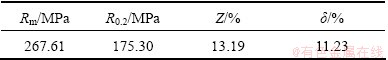
The material used in the present study is commercial extruded AZ31B magnesium alloy plate with a thickness of 10 mm. Its chemical composition is 2.8% Al, 1.1% Zn, 0.4% Mn, and balance of Mg (mass fraction). Before fatigue test the base mechanical properties of AZ31B magnesium alloy were conducted and the results are shown in Table 1.
Table 1 Mechanical properties of AZ31B magnesium alloy
Specimens (Fig. 1) were designed with the axis parallel to extrusion direction. Specimens were machined by wire-electrode cutting and polished with different grades metallographic sandpaper (15, 13, and 10 μm respectively) before fatigue testing.

Fig. 1 Specimens in tension (a) and fatigue (b) test (unit: mm)
The tension testing apparatus used was a DNS-100 universal testing machine. A PLG-200D high-frequency electromagnetic resonance fatigue test machine was used for fatigue tests in air. Fatigue tests were done by means of tension-tension loads (R=0.1). The load frequency was 99.6-100.2 Hz.
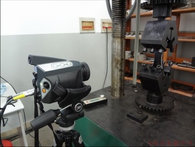
Fig. 2 Infrared system in fatigue test
Thermography detection was performed using a VarioCAM hr camera with a 320×240 focal plane array or 384×288 pixels (Fig. 2). The temperature sensitivity was better than 0.08 K at 303.13 K. Before tension and fatigue test, the specimen was covered with a thin opaque black paint layer in order to increase the thermal emissivity of the specimen surface.
A number of specimens were tested both above and below the fatigue limit. During each fatigue test, the surface temperature of specimen was recorded in real time and then the temperature curve was obtained. Test was stopped either when the specimens failed or after 107 cycles without evident damage. The maximum specimen surface temperature values (Ti) and room temperature values (Tr) were obtained. Then the difference was calculated (△T=Ti-Tr). Fatigue life of specimens was determined by means of thermographic techniques.
3 Results and discussion
3.1 Thermal frame works
Fatigue is a dissipative phenomenon involving damage accumulation. The mechanical energy over a cyclic loading involves the dissipation, the internal energy variation and the possible thermomechanical effects [13]. The temperature evolution during fatigue is affected by the thermoelastic, inelastic, heat-transfer effects, and the heat source outside the specimen (which is neglected in this paper). Combined with the balance laws of momentum and energy, and second law of thermodynamics, the coupled thermomechanical equation is obtained [8,14]:

 (1)
(1)
The basic thermomechanical quantities describing thermodynamic processes are: the density ρ and the specific heat capacity C, the conduction tensor k, the intrinsic dissipation  , the Cauchy stress tensor σ, the absolute temperature T, the strain tensor ε, the specific Helmholtz free energy ψ.
 represents the stored heat rate which is converted by mechanical energy. It is dependent on material property and load-up condition.
 illustrates the transference of heat by thermal conduction in which the heat passes through the material to make the temperature uniform in the specimen. And the thermal conduction between the specimen and grips and the specimen and air cannot be neglected.
 (2)
(2)
where d1 is the intrinsic dissipation. The irreversible deformation is the main reason that causes the accumulated damage under cyclic loading and the generation of heat in the specimen.
 (3)
(3)
where d2 is the thermomehcanical coupling sources. Within the elastic range and alternating loading, a reversible conversion process between the mechanical and thermal energy causes the temperature fluctuation on the surface of specimen.
3.2 Temperature evolution in magnesium alloy
With variation of loading state, the temperature evolution on the surface of magnesium alloy in tension and fatigue test is different. Moreover, the plastic deformation more likely happens in fatigue test.
3.2.1 Temperature evolution in tension test
The temperature evolution on the surface of magnesium alloy was varied with the loading (Fig. 3). As the stress increases the temperature evolution of magnesium alloy obviously undergoes four stages: linear decrease (stage 1), revers linear increase (stage 2), an abrupt increase (stage 3), and final drop (stage 4).
Temperature at stage 1 shows obvious decrease. Thermoelastic effect in the tension process that was first found by KELVIN can be used to explain this phenomenon. CHENG [15] derived the KELVIN formula to fit the solid material. It showed that the thermoelastic effect has relationship with the atomic density in crystal structure. The distance of atoms increases along with the tension force then the ability of heat conduction weakens. When the stress is up to the yield point, more heat is generated and released by plastic deformation in stage 2. Stage 3 is the area of instant fracture. The temperature increases abruptly, and then drops down in stage 4.
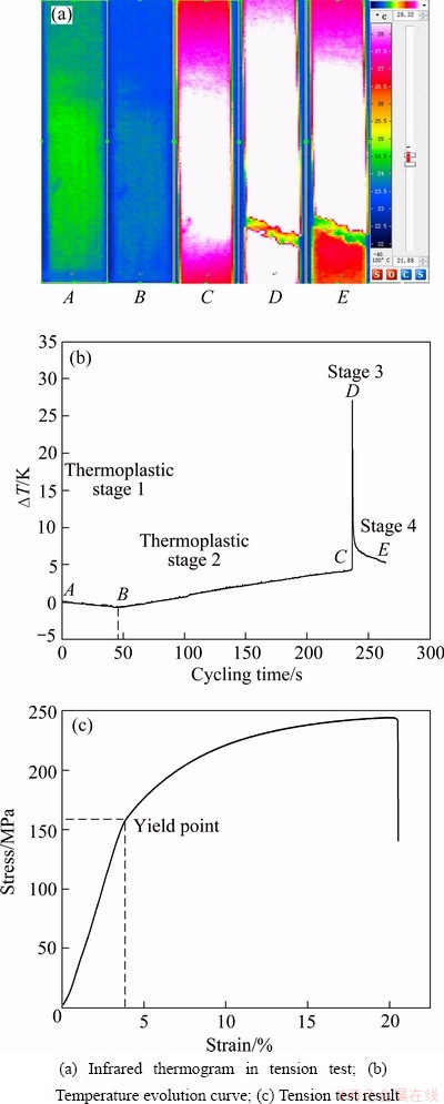
Fig. 3 Temperature evolution of magnesium alloy specimen in tension test
3.2.2 Temperature evolution in tension-tension fatigue test
Temperature on the surface of magnesium alloy under tension-tension loading varies along with the plastic deformation. As shown in Fig. 4 (σmax=130 MPa), when the cyclic loading is above the fatigue limit, the temperature evolution mainly undergoes five stages: initial increase (stage I), steep reduction (stage II), steady state (stage III), abrupt increase (stage IV), and final drop (stage V). Stage I is limited to numbers of cycles (in general, about 10% of the entire lifespan of the specimen). This stage is dominated by the inelastic effect, which causes local plastic deformation and yielding phenomenon. Temperature rises since the energy generated is greater than the heat transferred out of the specimen. The peak of temperature is caused by strain hardening [16]. Stage II presents the steep reduction of temperature after limited plastic deformation. This stage is dominated by the heat-transfer effect. Stage III shows a constant value of temperature that is still effected by plastic deformation, however the deformation rate is smaller than that in stage I. The temperature maintains stable under the transfer balance between the specimen and surrounding environment. In stage IV, macrocracks are formed gradually. The temperature increases rapidly for comparatively very small numbers of cycles. There is a local plastic deformation at the crack tip and the plastic work generated during this deformation is mostly converted to heat. As the crack expands before failure occurs, the deformation area decreases to the area around creak tip, temperature rises comparatively lower than that in stage I. This stage is believed as a warning of an imminent fracture, thereby, the estimation of the time to failure provides the capability of shutting down the machinery before a catastrophic break down occurs. Then, the specimen temperature drops down, as shown in stage V.
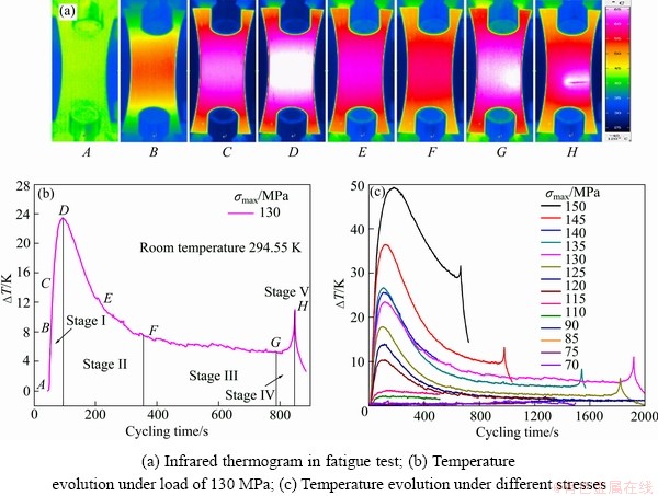
Fig. 4 Temperature evolution on the surface of magnesium alloy specimen
The process of fatigue fracture mainly exhibits macroscopic plastic deformation and microscopic glide reflection. For magnesium alloy, there is no evident yielding phenomenon. The plastic strain is expected to decrease during limited fatigue cycles due to the strain-hardening effect. Therefore, the temperature on the surface of specimen reaches up to the peak soon (point D in Fig. 4(b)). Subsequently, the temperature decreases until the heat finally reaches a relatively constant value due to the thermal equilibrium. Figure 4(b) shows the evolution of temperature vs number of cycles of magnesium alloy under different loads. It was shown that the energy dissipation of materials is considered to be a constant value under fatigue loading [8,17]. Peak temperature in stage I rises with the increase of cyclic loading. The intrinsic dissipation consumes lots of energy. Therefore, the cycle times before failure occur decreases even the stage III will not happen.
However, when repeated loading is applied, the peak temperature in stage I would not happen again (Fig. 5(a)). And the temperature soon reaches a constant. This demonstrates an irreversible deformation under cyclic loading.
Stress below fatigue endurance also causes damage in the material. Figure 5(b) shows the temperature evolution at initial stress applied of 100 MPa and cycling by 107 then at 130 MPa cycling by 4×10⁴. It shows that the temperature is quite different with that under the stress of 130 MPa directly. This means that intrinsic dissipation will happen under lower stress. The elastic limit increases by the strain hardening.
3.3 Fatigue life evaluation
Miner’s rule is generally accepted as the fatigue criterion for fatigue life estimation. The linear cumulative damage equation can be shown as
 (4)
(4)
where D is the fatigue damage, Ni is the number of loading cycles to failure under a constant stress range, ni is the real number of loading cycles. When there are k different stress ranges, then the fatigue failure of the structural component is considered to occur.
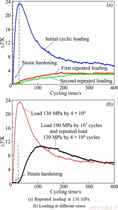
Fig. 5 Temperature evolution of magnesium alloy under different loading sequence
Miner’s rule considers that the total damage in the material is a constant value under continuation loading. In other words, internal energy of the material is also invariable. There is a limited plastic deformation in brittle materials as magnesium alloy. Therefore, the strain hardening will happen in limit cycle-index along with specific loading. The temperature converted by strain energy will reach the peak and then reduce steeply. However, the peak temperature in stage I caused by strain hardening will come up to a different level along with the loading increasing in different specimens. Furthermore, the percentage of peak temperature in the total evolution is also increases with the external loading. YAN et al [18] fitted the relationship between the peak temperature and maximum stress under cyclic loading. The temperature on the peak can be used to evaluate fatigue life of magnesium alloy.
Table 2 Parameters of temperature evaluation

The parameters needed are listed in Table 2, where △Ti is the peak temperature rise in stage I, ti represents the consumed time (cycle number) for △Ti, te is the consumed time at the final fracture under a specific loading, Pi is the specific value of ti and te which are shown in Eq. (5).
 (5)
(5)
The linear fitting between △Ti and Pi is shown in Fig. 6. Eq. (5) is converted as Eq. (6). Fatigue life of magnesium alloy can be calculated by temperature △Ti and loading time. And the fatigue cycle-index Ne can be determined as Eq. (7) where f represents the cycle frequency.
 (6)
(6)
 (7)
(7)
Equation (7) can be divided into two parts: when △Ti≤ 3.63 K, stress is under fatigue endurance and there is no apparent temperature change, therefore, the fatigue life will be infinite. This means that the specimen can be used safely without breaking; when △Ti>3.63 K, fatigue life is determined by the loading history and peak temperature (frequency is considered a constant). As △Ti rises, more energy in material will be consumed, which means the fatigue life is reduced.
The endurance limit cycled by 1×10⁷ is 110.7 MPa, while the temperature changes in the test are △T=3.56 K, which is close to 3.63 K.
The remaining life tested by temperature varies in stage I and normal method was compared Table 3. The calculated value of the remaining life Ne′ is less than the value Ne in the test. The fatigue life test by infrared thermography is safer than by common method. The temperature method will save time and low economic waste, and can be used to estimate fatigue property in the structure design under cyclic loading.
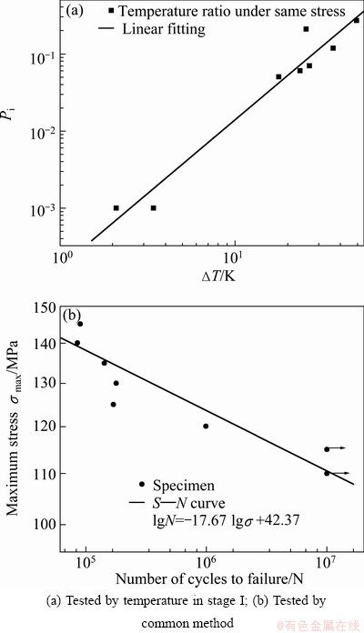
Fig. 6 Fatigue property of magnesium alloy in high-cycle fatigue test
Table 3 Comparison between Ne and Ne′

4 Conclusions
1) Fatigue failure is a dissipative phenomenon involving damage accumulation. The mechanical energy over a cycle involves the dissipation, the internal energy variation and effects of the temperature on the surface of specimen.
2) With the stress increasing during tension process, the temperature evolution of magnesium obviously undergoes four stages: linear decrease (stage 1), reverse linear increase (stage 2), an abrupt increase (stage 3), and final drop (stage 4).
3) When the cyclic loading is above the fatigue limit, the temperature evolution mainly undergoes five stages: initial increase (stage I), steep reduction (stage II), steady state (stage III), abrupt increase (stage IV) and final drop (stage V).
4) Temperature variation in stage I is affected by intrinsic dissipation under cyclic loading that can be used to evaluate the fatigue life.
5) The critical temperature variation that causes the fatigue failure is 3.63 K. When △T≤3.63 K, the material is safe under cyclic loading. When △T>3.63 K, fatigue life is determined by cycle index and peak temperature.
References
[1] CHEN Zhen-hua. Wrought magnesium alloy [M]. Beijing: Chemical Industry Press, 2005, 5: 1-3. (in Chinese)
[2] MAO Y, CAI, Q W, WEI, S B. Influence of deformation parameters on texture of AZ31Magnesium alloy [J]. Journal of Plasticity Engineering, 2008, 15(6): 4-7.
[3] MORITA S, OHNO N, TAMAI F, KAWAKAMI. Fatigue properties of rolled AZ31B magnesium alloy plate [J]. Transactions of Nonferrous Metals Society of China, 2010, 20(s2): s523-s526.
[4] AMIRI M, KHONSARI M M. Rapid determination of fatigue based on tgemperature evolution: Fully reversed bending load [J]. International Journal of Fatigue, 2010, 32: 382-389.
[5] UMMENHOFER T, MEDGENBERG J. On the use of infrared thermography for the analysis of fatigue damage processes in welded joints [J]. International Journal of Fatigue, 2009, 31: 130-137.
[6] ROSA G L, RISITANO A. Thermographic methodology for rapid determination of the fatigue limit of materials and mechanical components [J]. International Journal of Fatigue, 2000, 22: 65-73.
[7] CURA F, CURTI G, SESANA R. A new iteration method for the thermographic determination of fatigue limit in steels [J]. International Journal of Fatigue, 2005, 27: 453-459.
[8] YANG B, LIAW P K, WANG H, JIANG L, HUANG J Y, KUO R C, HUANG J G. Thermographic investigation of the fatigue behavior of reactor pressure vessel steels [J]. Materials Science and Engineering A, 2001, 314: 131-139.
[9] LUONG M P. Infrared thermographic scanning of fatigue in metals [J]. Nuclear Engineering and Design, 1995, 158: 363-376.
[10] CHEN N Z, WANG G, SOARES C G. Palmgren-Miner’s rule and fracture mechanics-based in section planning [J]. Engineering Fracture Mechanics, 2011, 78: 3166-3182.
[11] JARDIN A, LEBLOND J B, BERGHEZAN D, PORTIGLIATTI M. Definition and experimental validation of a new model for the fatigue of elastomers incorporating deviations from Miner’s linear law of cumulative damage [J]. Procedia Engineering, 2010, 2: 1643-1652.
[12] SIRJWARDANE S, OHGA M, DISSANAYAKE R, TANIWAKI K. Application of new damage indicator-based sequential law for remaining fatigue life estimation of railway bridages [J]. Journal of Constructional Steel Research, 2008, 64: 228-237.
[13] MENEGHETTI G, RICOTTA M. The use of the specific heat loss to analyse the low- and high-cycle fatigue behaviour of plain and notched specimens made of a stainless steel [J]. Engineering Fracture Mechanics, 2012: 81: 2-16.
[14] GIANCANE S, CHRYSOCHOOS A, DATTOMA V, WATTRISSE B. Deformation and dissipated energies for high cycle fatigue of 2024-T3 aluminium alloy [J]. Theoretical and Applied Fracture Mechanics, 2009: 52: 117-121.
[15] CHENG Z F. The insulation constant and Kelvein formula in solid state thermodynamics [J]. Journal of Southwest China Normal University: Natural Science, 2000, 25(3): 253-256.
[16] CRUPI V, GUGLIELMINO E, MAESTRO M, MARINO A. Fatigue analysis of butt welded AG36 steel joints [J]. Thermographic Method and Design S-N Cure Marine Structures, 2009, 22: 373-386.
[17] FAN J L, GUO X L, WU C W, ZHAO Y G. Research on fatigue behavior evaluation and fatigue fracture mechanisms of cruciform welded joints [J]. Materials Science and Engineering A, 2011, 528: 8417-8427.
[18] YAN Z F, ZHANG H X, WANG W X, WANG K, PEI F F. Infrared thermography technology predicting fatigue property of AZ31B magnesium alloy [J]. Materials for Mechanical Engineering, 2012, 36(2): 72-75.
基于红外热像法的AZ31B镁合金温度演化与疲劳寿命预测
闫志峰,张红霞,王文先,王 凯,裴飞飞
太原理工大学材料科学与工程学院,太原 030024
摘 要:采用红外热像仪测量挤压态AZ31B镁合金板材在拉伸和疲劳试验过程中试样表面的温度变化。对试样在不同载荷作用下的产热机制进行分析,并建立P―△T曲线,对疲劳损伤过程的温度变化临界值进行计算。结果表明:AZ31B镁合金板材拉伸和疲劳过程中的温度变化趋势不同。拉伸过程温度变化包括4个阶段:线性降低、反向线性升高、温度陡升、最终下降。初始温度下降是由弹性拉伸阶段的热弹性效应造成。在循环载荷作用下,当载荷高于疲劳极限时,温度演化主要分为5个阶段:初始温度升高阶段、温度迅速下降阶段、温度稳定阶段、温度快速升高阶段、最终下降阶段。疲劳过程中的应变硬化造成初始温度升高至峰值温度,利用峰值温度与应力关系可以预测镁合金疲劳寿命。AZ31B镁合金达到疲劳极限时的临界温度变化为3.63 K。当△T≤ 3.63 K时,材料在循环载荷下安全使用;当△T >3.63 K 时,疲劳寿命取决于循环次数与加载初始峰值温度。
关键词:AZ31B镁合金;高周疲劳;热像图分析;温度演化
(Edited by Chao WANG)
Foundation item: Project (51175364) supported by the National Natural Science Foundation of China; Projec (2013011014-3) supported by the Natural Science Foundation of Shanxi Province, China
Corresponding author: Wen-xian WANG; Tel: +86-351-6010076; E-mail: wwx960@126.com
DOI: 10.1016/S1003-6326(13)62681-3

