
Hole flanging with ironing process of two-ply thick sheet metal
HUANG Yuung-ming(黄永明)
Department of Mechanical and Computer-Aided Engineering, St. John’s University,
Taipei 25135, Taiwan, China
Received 5 September 2006; accepted 31 December 2006
Abstract: An incremental updated Lagrangian elasto-plastic finite element method(FEM) was employed to analyze the hole-flanging with the ironing of circulate plates using a pre-determined smaller hole at the center of the two-ply sheet metals. An extended rmin technique was employed such that each incremental step size can be determined not only by the yielding of an element Gaussian point, but also by the change under the boundary conditions of penetration, separation, and the alternation of the sliding-sticking state of friction along the tool-sheet interface. Two-ply sheet metals are generally composed of metals that have different mechanical properties. Thus, the forming process of these materials is complicated. A number of experiments and simulations were performed using a conical punch with a cone angle of 45?. The experimental results were compared with FEM-simulated results. It is found that using the elasto-plastic FEM can effectively predict the generation process of the deformed shape until unloading. The calculated sheet geometries and the relationship between punch load and punch travel are in good agreement with the experimental data.
Key words: hole-flanging; ironing; elasto-plastic; finite element method; sliding-sticking friction
1 Introduction
Hole-flanging is one of the important techniques of sheet metal forming, and has been used widely when manufacturing industrial parts. After forming, the products are mainly offered for thread cutting to carry on with second machining and coordinated as a strut when connecting pipelines or supporting other parts[1]. One of the related studies is that of JOHNSON et al[2]. They performed an experimental study on the deformation of circular plates leading to fracture of the lip in the hole-flanging process. They applied the plastic anisotropy of the Hill onto the plane stress condition to forecast the change in thickness along the edge of expanded hole on the sheet material and to discuss the distortion pattern of the expanded hole of the curving flanged part after the sheet material was burst. They also discussed the influence of the plastic properties of the material and processing geometry on hole-flanging. TANG[3] proposed a finite element method(FEM) using the membrane shell theory while ignoring the bending effect. He used four different punch shapes, i.e. hemispherical, ellipsoid, cylindrical and conical to analyze the distribution of the sheet material’s stress and strain during the hole-flanging process. The result showed that the strain path is independent of the punch shapes during the formation process, but that the maximum punch load depends on the punch shapes. TAKUDA et al[4] used pure zirconium sheet to perform the deep-drawing and bore-expanding test in order to obtain its basic formability. They also carried out a simulation using the rigid-plastic FEM and the criterion of ductile fracture to predict the forming limitation of zirconium sheet. The results showed that in the process of deep-drawing and bore-expanding, the forming limitation of zirconium sheet would decrease significantly along with the reduction in punch profile radius. The forming characteristics of hole-flanging with ironing for bimetal sheets have been studied recently using a conical punch with a cone angle of 45? by KUMAGAI et al[5]. Their experimental and simulated results demonstrate that rigid-plastic FEM can effectively simulate the forming process. YAMADA et al[6] studied the effects of initial yield stress and strain hardening on bore-expanding using the incremental theory of plasticity with a flat-headed cylindrical punch to determine the stress and strain distribution. WANG et al[7] found that the state of stress in the flanged neck is dominantly uniaxial according to a total strain membrane theory of rigid-plasticity for analysing the stretch flanging of a clamped sheet of anisotropic material using a spherical punch. TAKUDA et al[8] examined the formability of bore-expanding using the rigid-plastic FEM with the ductile fracture criterion to find the fracture initiation sites of sheets. JOHNSON et al[9-10] found that the lip always fractures at the outer edge owing to excessive hoop tension and tensile instability when a conical punch is used. Besides the plastic properties of material, such as strain-hardening and anisotropy, which affect the formability in the hole-flanging process[11-12], other external influen- cing factors include the lubrication condition, the punch shapes and the clearance between the punch and die[13-15]. The effect of cone semi-angle of a truncated conical punch on the limitation of formability in the process has not been explored.
In this study, the elasto-plastic finite-element code, developed from the updated Lagrangian formulation, was adopted to simulate the hole-flanging with ironing process under variable parameter conditions. An experiment from Ref.[5] was used to confirm the accuracy of theoretical estimation and the formula developed using the elasto-plastic FEM.
2 Description of basic theory
2.1 Variational principal
The variational principal, with respect to current deformed material on the basis of an updated Lagrangian formulation using Jaumann rate of Cauchy stress, can be expressed as[16]
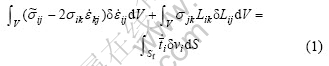
where 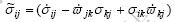 is the Jaumann rate of Chaucy stress, σij is the Eluer stresses,
 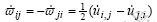 is the anti-symmetrical rotation rate tensor,
  is the strain rate tensor,
 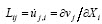 the velocity gradient tensor, Xi is the spatial fixed Cartesian coordinate,
  is the velocity of node,
  is the rate of the nominal traction, V and Sf are the material volume and surface where the traction is prescribed.
2.2 Finite element discretization
As the principle of virtual work rate equation and the constitutive relation are linear equation of rates, these can be replaced by increments defined with respect to any monotonously increasing measure, such as the tool displacement increment.
Following the standard procedure of finite elements to form the whole global stiffness matrix, we obtain

where
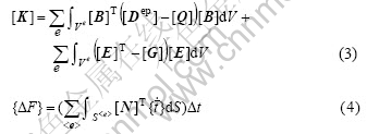
In these equations, [K] is the global tangent stiffness matrix, [Dep] is the elemental elasto-plastic constitutive matrix, [N] is the shape function matrix, [ B] is the strain rate-velocity matrix, [E] is the velocity gradient-velocity matrix, {?u} denotes the nodal displacement increment, and {?F} denotes the prescribed nodal force increment. [Q] and [G] are defined as stress correction matrices due to the current stress states at any stage of deformation.
2.3 Treatments of elasto-plastic and contact problems
The contact condition between tools and blank on each node should remain in the same state at the moment of one incremental deformation. In order to satisfy this requirement, the r-minimum method proposed by YAMADA et al[17], is adopted and extended to treat the elasto-plastic and contact problem. The increment of each loading step is controlled by the smallest value from r1 to r6, i.e.

where r1 confirms that the state of the element stress is the same as that on the yielding surface when the elemental stress is greater than the yielding stress, r2 and r3 constrain the largest principal strain and the rotation increment, respectively, to the linear relation, r4 causes the free nodes to contact the tools, r5 causes the contact nodes to depart from the tool surface, and r6 gives the alternation of a friction state from sliding to sticking for the contacted node along the tool-blank interface.
3 Numerical analysis
The experimental setup and the analytical model of hole-flanging with ironing process were developed under axisymmetric condition. Because of the symmetry of the blank, only the right-half portions of the tools and work pieces were modeled. A conical punch with a cone angle of 45? and a diameter (Dp) of 18.0 mm was used. The punch had 2.0 mm land length and 1 mm punch corner radius, whilst the dies, had 1.0 mm die profile radius. The clearance (Cr) between the punch and the dies was controlled by changing the inside diameter of the dies (Dd). Setting the ratio of clearance to thickness (Rc=Cr/T) at less than unity, ironing was applied to the blank.
An automatic mesh program was employed to generate the finite-element mesh grid. The finite-element mesh grids comprised the four-node-quadrilateral element in four integration points for selective reduced integration, which were efficient for axisymmetric metal forming. In this study, 96 elements and 125 nodes were meshed. Fig.1(a) shows the profile of the die and punch, and the initial shape and the finite-element mesh of the blank used in the calculation. In the local coordinates, axis l denotes the tangential direction of the contact between the sheet material and the tool, while axis n denotes the normal direction of the same contact. Constant coordinates (r, z) and local coordinates (l, n) describe the nodal force, displacement and element’s stress and strain.
Fig.1(b) shows the boundary conditions of the deformed geometry of the sheet at a certain stage of the hole-flanging with ironing process. The boundary condition of the nodes will be changed as the hole- flanging with ironing process proceeds.
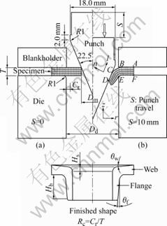
Fig.1 Dimensions of tool geometry and initial shape with finite-element mesh of sheet (a) and boundary conditions of deformed sheet geometry (b)
The material characteristics of the bi-metallic sheet metals[5] analyzed in this simulation are listed in Table 1.
Table 1 Material characteristics of bi-metallic sheet metals

The initial hole diameters (Dm) were 9.0, 10.0, 11.0, 12.0, 13.0 and 14.0 mm. Fig.2 shows the deformation types, Type Cu was named for the process where the cladding Cu faced the inner wall of the lip, while Type Al was named for the process where the matrix Al faced the inner wall of the lip.
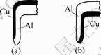
Fig.2 Deformation types: (a) Type Cu; (b) Type Al
4 Results and discussion
Figs.3 and 4 indicate the relationship between the punch force and punch travel under Type Cu and Type A1, respectively when the initial hole diameter Dm=9.0 mm. Regarding Type Cu in Fig.3, when Rc=0.99, the FEM-simulated result is consistent with the experimental finding. When Rc=0.49 before the hole-flanging process reaches the maximum punch load, the FEM-simulated result is consistent with the experimental finding. Nevertheless, after the drawing process reaches the maximum punch load, the FEM-simulated result is lower than the experimental finding. The reasons can be easily explained.
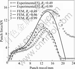
Fig.3 Relation between punch force and punch travel (Type Cu, Dm=9.0 mm)
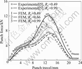
Fig.4 Relation between punch force and punch travel (Type Al, Dm=9.0 mm)
After the hole-flanging process reaches the maximum punch load, the ironing function is more obvious. In addition, paraffin base oil was used as the lubricating oil in the previous experiment[5]; with lower viscosity, this lubricating oil creates higher frictional shear stress of ironing after the hole-flanging process reaches the maximum punch load. Moreover, the experimental load value calculated is larger than the simulated one. The punch load value at Rc=0.66 is closer to the one when Rc=0.99. However, the value is still situated between the correspondent values at Rc=0.49 and Rc=0.99.
Regarding Type A1 in Fig.4, when the clearance-thickness ratio Rc=0.99 and Rc=0.49, the FEM-simulated result is consistent with the experimental finding. In the experiment reported in Ref.[5], MoS2 was used as the lubricating oil because of its good lubrication effect. Therefore, at Rc=0.49 after the hole-flanging process reaches the maximum punch load, the frictional shear stress almost maintains its definite value and the experimental load will be lowered, thus keeping the consistency between the simulated computing value and experimental load value. There is another reason that accounts for why the punch load of Type Cu in Fig.3 is higher than that of Type A1 in Fig.4 when Rc=0.49. At the end of the ironing process, partial aluminum, which is Type Cu’s foundation will become the inner wall of hole-flanging, and cause the punch land to slide on the aluminum coated with the paraffin base oil to have a poor lubrication effect.
Fig.5 indicates the relationship between the punch force and punch travel of hole-flanging ironing at different initial hole diameters when the clearance- thickness ratio of Type Cu and Type A1 is Rc=0.49. With a larger initial hole diameter, there is fewer sheet hanging on the die surface that will need ironing forming. So, the forming can be accomplished with shorter punch travel. At the same time, the maximum punch load received with larger initial hole diameter is larger than that with smaller initial hole diameter, because the hanging sheet is shorter and has good rigidness, and thus will not be bent or deformed easily.
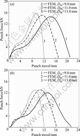
Fig.5 Punch force of hole-flanging with ironing process of Type Cu (a) and Type Al (b) under different initial hole diameters (Rc=0.49)
Fig.6(a) shows the result of hole-flanging ironing process simulation of Type Cu when Rc=0.49 and Dm=9.0 mm, indicating the deformed shape. The last shape is the final shape using A and B as the unloading contraction points. Fig.6(b) denotes the nodal velocity distributions during forming. The last shape is the nodal velocity distributions after unloading. From the figure it is clear that the sheet is slowly bent and slided into the dies, then extruded and finally ironing formed by punch and die. The condition of the contact surface of sheet and tools, which may determine that the extended rmin technique can trace adequately the whole deformation history of the hole-flanging with ironing process. Meanwhile, the correct deformation procedures of hole-flanging with ironing process can be obtained from the nodal velocity distributions. Fig.6(c) shows the result of hole-flanging with ironing process simulation of Type A1 when Rc=0.99 and Dm=9.0 mm. Comparing Fig.6(c) with Fig.6(a) shows that different deformation types and clearance-thickness ratios have great influences on the forming condition.
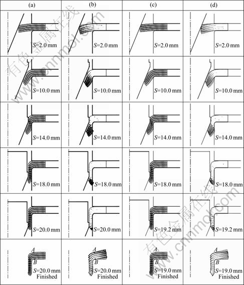
Fig.6 Hole-flanging with ironing process of Type Cu (Rc=0.49, Dm=9.0 mm) and Type Al (Rc=0.99, Dm=9.0 mm): (a) Deformed geometries of Type Cu; (b) Nodal velocity distributions of Type Cu; (c) Deformed geometries of Type Al; (d) Nodal velocity distributions of Type Al
Fig.7 shows the relationship between the ironing lip length (Hb), initial hole diameter, and clearance-thickness ratio. For Type Cu and Type A1, when Rc=0.99, the ironing lip length Hb is zero because the clearance (Cr) between the punch and die is bigger than the thickness of sheet metal (T). Therefore, there is no ironing function toward the outer wall. When Rc=0.49, Hb of Type Cu and Type A1 are almost equal because Cr is much smaller than T. With the sheet metal extruding between the punch and die, ironing functions on the entire surface of the flanging outer wall. Hb of Type Cu and Type A1 are increased along with the decrease in Dm and Rc. When Rc=0.66 and Rc=0.82, Hb of Type Cu is greater than that of Type A1. In other words, ironing with Type Cu is easier than that with Type A1 because when ironing Type A1, the aluminum of the flanging inner wall and punch will do a whole process contacting forming.
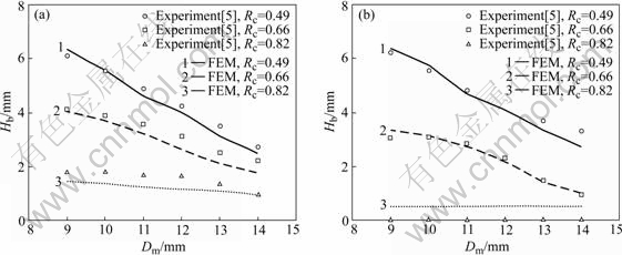
Fig.7 Relation between ironing lip lengths (Hb) and initial hole diameter (Dm): (a) Type Cu; (b) Type Al
Fig.8 shows the respective impact of Type Cu and Type Al ironing on the drawing length Hs. As can be seen, the experimental results agree considerably well with the FEM-simulated ones. The drawing length Hs is inversely proportional to Rc. In other words, ironing function is effective in improving product’s shape. Generally speaking, the chance of Type Cu’s Hs decreasing along with the increase in initial hole diameter is smaller than that of Type A1’s. For Type A1, the chance of Hs decreasing along with the decrease in Rc is greater than that for Type Cu, since partial matrix A1 opposed the pressing of punch.
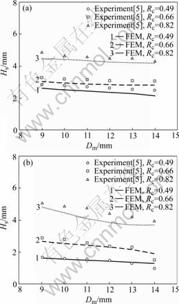
Fig.8 Relation between drawing length (Hs) and initial hole diameter (Dm): (a) Type Cu; (b) Type A1
Fig.9 indicates the cross-section of the simulated finished lip with different clearance-thickness ratios Rc when Dm=9.0 mm. When Rc=0.99, since Cr is large, only partial sheet will fit with the shoulder angle of dies. When Rc=0.99 and Rc=0.82, it is observed that the inner wall of the finished lip is curved; but when Rc=0.66 and Rc=0.49, this curving disappears because the sheet is extruded ironing between the punch and die. Therefore, the ironing function can improve the shape of hole-flanging process.

Fig.9 Cross-sectional views of finished lip at various clearance-thickness ratios (Rc) when Dm= 9.0 mm: (a) Type Cu; (b) Type Al
Fig.10 shows the cross-section of the simulated finished lip with change of Dm when Rc=0.49. Regarding the forming of sheet with different initial hole diameters, the thickness of cladding Cu sheet of Type Cu after forming is thinner than that of Type A1. The explanation of the above result is that the material of Type A1 is in contact with the punch during the forming consistently and burnished by the punch. The thickness of the cladding Cu in the finished lip of Type A1 tends to decrease with decreasing Dm. This tendency is caused by the burnishing of the hole edge in the early forming stages.
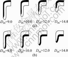
Fig.10 Cross-sectional views of finished lip at various initial hole diameters when Rc= 0.49: (a) Type Cu; (b) Type Al
Fig.11 shows the effects of Rc on web angle and flange angle. With small Rc, the spring-back of web and flange will also be small, because the ones with small Rc will have greater ironing effects on metal sheet that makes the spring-back of web and flange small to have better perpendicular look, which improves the shape of product.
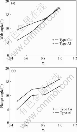
Fig.11 Effect of clearance-thickness ratio (Rc) on web angle (a) and flange angle (b)
5 Conclusions
1) When producing Type A1, its matrix A1 sheet is always the inner wall formed by hole-flanging and burnished by a punch. When producing Type Cu, although the cladding Cu is the inner wall of the lip formed by hole-flanging, partial matrix A1 will be turned to the same side of the cladding Cu. This overhang is increased when increasing initial hole diameter.
2) During the process, the thickness of cladding Cu will decrease along with the increase in initial hole diameter, regardless whether it is Type Cu or Type A1. Apart from that, even with the same initial hole diameter, the decrease in thickness of the cladding Cu is larger for Type Cu than for Type Al.
3) Ironing can effectively improve the finished shape of the hole-flanging.
4) The results of a forming load, coming from the initial shape to the last deformed shape, demonstrate a suitable approximation between experimental findings and theoretical calculations, which indicates that the entire deformation history can be successfully traced. This information can be used as references for improving the manufacturing process and the design of tools.
References
[1] LANGE K. Handbook of the Metal Forming [M]. New York: McGraw-Hill, 1985: 512-516.
[2] JOHNSON W, CHITKARA N R, MINH H V. Deformation mode and lip fracture during hole-flanging of circular plates of anisotropic materials [J]. Trans ASME J Eng Ind, 1977, 99: 738-748.
[3] TANG S C. Large elasto-plastic strain analysis of flanged hole forming [J]. Comp Struct, 1981, 13: 363-370.
[4] TAKUDA H, HATTA N. Numerical analysis of formability of a commercially pure zirconium sheet in some sheet forming processes [J]. Mater Sci Eng A, 1998, A242: 15-21.
[5] KUMAGAI T, SALKI H, MENG Y. Hole flanging with ironing of two-ply thick sheet metals [J]. J Mater Pro Tech, 1999, 89/90: 51-57.
[6] YAMADA Y, KOIDE M. Analysis of the bore-expanding test by the incremental theory of plasticity [J]. Int J Mech Sci, 1968, 10: 1-14.
[7] WANG N M, WENNER M L. An analytical and experimental study of stretch flanging [J]. Int J Mech Sci, 1974, 16: 135-143.
[8] TAKUDA H, MORI K, FUJIMOTO H, HATTA N. Prediction of forming limit in bore-expanding of sheet metals using ductile fracture criterion [J]. J Mater Pro Tech, 1999, 92/93: 433-438.
[9] JOHNSON W, CHITKARA N R, IBRAHIM A H, DASGUPTA A K. Hole flanging and punching of circular plates with conically headed cylindrical punches [J]. J Strain Analysis, 1973, 8: 228-241.
[10] CHITKARA N R, JOHNSON W. Hole flanging and piercing of circular plates [J]. Sheet Metal Industries, 1974, 51: 635-637.
[11] LEU D. Finite-element simulation of hole-flanging process of circular sheets of anisotropic materials [J]. Int J Mech Sci, 1996, 38: 917-933.
[12] TAKUDA H, KIKUCHI S, HATTA N. Formability of a commercially pure zirconium sheet [J]. J Mater Pro Tech, 1998, 84: 117-121.
[13] LEU D, CHEN T, HUANG Y. Influence of punch shapes on the collar-drawing process of sheet metal [J]. J Mater Pro Tech, 1999, 84: 134-146.
[14] HUANG Y, CHIEN K. Influence of punch profile on the limitation of formability in the hole-flanging process [J]. J Mater Pro Tech, 2001, 113: 720-724.
[15] HUANG Y, CHIEN K. The formability limitation of the hole-flanging process [J]. J Mater Pro Tech, 2001, 117: 43-51.
[16] MCMEEKING R M, RICE J R. Finite element formulations for problems of large elastic-plastic deformation [J]. Int J Solids Structures, 1975, 11: 601-606.
[17] YAMADA Y, YOSHIMURA N, SAKURAI T. Plastic stress-strain matrix and its application for the solution of elastic-plastic problems by the finite element method [J]. Int J Mech Sci, 1968, 10: 343-354.
Corresponding author: HUANG Yunng-ming; Tel: +86-886-28013131-6702; E-mail: hyming@mail.sju.edu.cn
(Edited by CHEN Wei-ping)

