Һ��������ȴ�����¼�������AZ31Bþ�Ͻ������Բ�
��Դ�ڿ����й���ɫ����ѧ��(Ӣ�İ�)2015���5��
�������ߣ������� ʩ��ϼ ������ ������
����ҳ�룺1446 - 1453
�ؼ��ʣ�þ�Ͻ𣻼������������Һ����ȴ����Ӳ�ȣ���ʴ����
Key words��magnesium alloy; laser surface melting; liquid nitrogen-assisted cooling; microhardness; corrosion resistance
ժ Ҫ�������������������þ�Ͻ������Է���֮һ��Ϊ�˽�һ�����þ�Ͻ�ı������ܣ������Һ��������ȴ�뼤���������ϵķ�����ͨ���ı�þ�Ͻ�����¶ȣ��ӿ���Բ�������ٶ�������þ�Ͻ�ı������ܡ�������������������������������ȣ�Һ��������ȴ�����£�þ�Ͻ�����γ�һ��ϱ��ĸ��Բ㣬��������ϸ�����������ϱ����γ��˴��������״�����������ֲ������������ķǾ���֯������Ӳ��Ϊ HV 90~148�����������������������(Ӳ��Ϊ HV 60~105)�����Լ40%����3.5%NaCl��Һ�н��е绯ѧ���ԣ����������Һ��������ȴ�����¸��Բ����ʴ���������, ��ԭ����Ҫ�����ڿ������̹����о���ϸ�����ڶ��� ��-Mg17Al12���ٷ��估�ֲ��Ǿ���֯�ۺ����صĽ����
Abstract: Laser surface melting (LSM) is a high-energy surface treatment that allows modification of the microstructure and surface properties of Mg alloys. In the present work, an attempt of LSM on magnesium alloy with liquid nitrogen-assisted cooling (LNSC) was carried out to get the higher cooling rate and improve the surface properties. The experimental results were compared with those of Ar gas protection at room temperature. The samples after LSM with LNSC resulted in a thinner melted layer, a highly homogeneous, refined melted microstructure and formed a lot of worm-like nanocrystals and local amorphous structures. Microhardness of the melted layer with LNAC was improved to HV 90-148 as compared to HV 65-105 of the samples with Ar gas protection. The corrosion resistance of the melted layer in a 3.5% NaCl solution (mass fraction) was improved because of the grain refinement and redistribution of ��-Mg17Al12 phases following rapid quenching associated with the process.
Trans. Nonferrous Met. Soc. China 25(2015) 1446-1453
Ze-qin CUI1,2, Hai-xia SHI1, Wen-xian WANG1,2, Bing-she XU1,2
1. College of Materials Science and Engineering, Taiyuan University of Technology, Taiyuan 030024, China;
2. Key Laboratory of Interface Science and Engineering in Advanced Materials, Ministry of Education, Taiyuan University of Technology, Taiyuan 030024, China
Received 29 September 2014; accepted 27 January 2015
Abstract: Laser surface melting (LSM) is a high-energy surface treatment that allows modification of the microstructure and surface properties of Mg alloys. In the present work, an attempt of LSM on magnesium alloy with liquid nitrogen-assisted cooling (LNSC) was carried out to get the higher cooling rate and improve the surface properties. The experimental results were compared with those of Ar gas protection at room temperature. The samples after LSM with LNSC resulted in a thinner melted layer, a highly homogeneous, refined melted microstructure and formed a lot of worm-like nanocrystals and local amorphous structures. Microhardness of the melted layer with LNAC was improved to HV 90-148 as compared to HV 65-105 of the samples with Ar gas protection. The corrosion resistance of the melted layer in a 3.5% NaCl solution (mass fraction) was improved because of the grain refinement and redistribution of ��-Mg17Al12 phases following rapid quenching associated with the process.
Key words: magnesium alloy; laser surface melting; liquid nitrogen-assisted cooling; microhardness; corrosion resistance
1 Introduction
The attractive mechanical properties of magnesium and its alloys increase their use in many technical applications, such as automobile, aerospace components and degradable biomaterial [1-3]. However, their applications are often restricted because of their poor surface properties. To overcome the restriction of these drawbacks, the surface properties of Mg alloys therefore need to be ameliorated.
Surface modification is a common way to improve the surface properties. At present, some techniques have been used to improve their corrosion rate, such as electrochemical deposition [4,5], electroless plating [6,7], plasma electrolytic oxidation [8,9], physical vapor deposition [10], ion implantation [11] and laser surface treatment [12-14]. Especially, laser surface melting (LSM) is a well-recognized method for generating thin melted layers on the alloy surface with a refined, relatively uniform microstructure, and dissolving the intermetallic phases [13,15]. LSM treatment has been mostly investigated for structural magnesium. The early studies of LSM of magnesium employing high power continuous-wave CO2, Nd:YAG lasers and high power diode lasers (HPDLs) have been also used, taking advantage of their higher energy efficiency and lower costs. WANG et al [16] found that the corrosion resistance by LSM was improved, and the grains were refined. TALTAVULL et al [17] found that some samples had corrosion rates higher than the average corrosion rate, and some were lower. GUAN et al [18] showed that all laser-melt surfaces had improved corrosion resistance. In contrast, CHAKRABORTY BANERJEE et al [19] pointed out that LSM treatment did not significantly improve the corrosion resistance of ZE41. Recently, much attention has been focused on excimer laser radiation sources, with pulse durations in the nanosecond range [20]. Such processing, with extremely fast cooling rates of up to 1011 K/s, favors the formation of rapidly solidified microstructures, largely free of segregation and intermetallic phases with minimal thermal effect [21].
The above studies mostly get rapid solidification rates by changing the type of the laser. In this work, an attempt of LSM on AZ31B magnesium alloy with liquid nitrogen-assisted cooling was carried out to get higher cooling rates and improve the surface properties. This method accelerates solidification rates of magnesium alloys by altering the substrate��s temperature. The aim of the present investigation is to evaluate the microstructural changes and their impact on microhardness and corrosion resistance of the alloy. The results were analyzed and compared with those of the Ar gas protection at room temperature.
2 Experimental
A 3 mm thick AZ31B Mg alloy sheet with 3.22% Al, 1.15% Zn, 0.400% Mn, 0.0133% Si, 0.0019% Fe (mass fraction), and balanced Mg was used in this work. The material was cut into specimens with dimensions of 100 mm��100 mm��3 mm for laser treatment. LSM was carried out using a pulsed Nd:YAG laser with a wavelength of 1064 nm. The laser processing parameters, optimized from adequate number of preliminary experiments during the present efforts, are listed in Table 1. Prior to laser treatment, the specimens were ground with an 800 SiC grit so as to eliminate surface oxides and obtain cleaned surfaces, then rinsed in ethanol, and finally dried in air. The plate was immersed in a steel container with liquid nitrogen (�C196 ��C) resulting in about 2 mm-thick deep cryogenic liquid layer over the target to reach rapidly cooling rates and avoid surface oxides, as shown in Fig. 1. An overlap ratio of 30% between the laser-melted tracks was selected during laser melting. In order to contrast test results, another plate was melted with the same parameters by laser and with 99.99% high purity Ar gas (gas flow of 5 L/min) protection environment at room temperature.
Table 1 Parameters of LSM
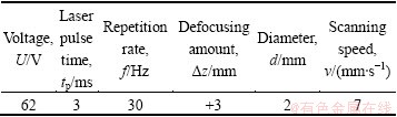
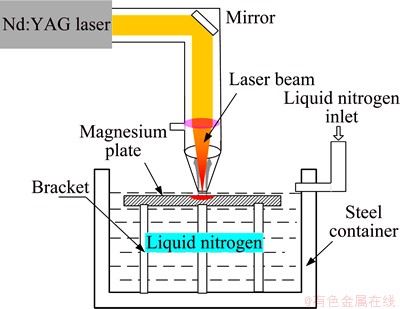
Fig. 1 Schematic diagram of LSM in liquid nitrogen
The melted samples were cut along transverse section, then polished and etched using a 5 % nitric acid water solution for 5-7 s. Detailed analyses of the phases of the melted surface layers were carried out with a X-ray diffraction (XRD) (Model Y-2000) with Cu K�� radiation. The microstructures in the given depth from the surface to the matrix of the samples were observed by a CMM-20 optical microscope (OM) and Tecnai G2 F20 S-TWIN transmission electron microscope (TEM). The plane-view TEM foil of melted layer was obtained firstly by polishing the sample mechanically on the untreated side until it was about 50 ��m in thickness; Then, the foil was thinned by ion-milling using a Gatan precision ion polishing system (PIPS) with a small incident angle (6��), the vacuum degree of 10-4 Pa, the high pressure of 4 keV, the ion beam current of 0-8 ��A. The microhardness of the cross-sectional plane of the melted layers and the substrate were measured by a HVS-1000A Vickers tester with a testing load of 5 g and a loading time of 15 s. Electrochemical tests were carried out in a 3.5% NaCl solution without stirring, using a specimen with an area of 1 cm2 exposed to the solution in a conventional three- electrode PGSTAT30 system, with the melted layers as the working electrode, a silver/silver chloride (Ag/AgCl) saturated with KCl as reference electrode, a platinum rod as counter electrode. Polarization was carried out from -2 V to 1 V at a scan rate of 0.5 mV/s. The masses of the pre- and post-corrosion samples were measured by an electronic scale (Model JY501, accuracy 0.0001g).
3 Results and discussion
3.1 Microstructural characterization
The initial microstucture of as-received Mg alloy AZ31B was coarse grain cellular type structure with grain size in the range of 10-50 ��m as shown in Fig. 2. It is made up of ��(Mg) and a few ��-Mg17Al12 distributed along grain boundaries.
After LSM, both of the laser melted layers surface displayed a complex rippled surface morphology. Figure 3 shows the low magnified cross-sectional OM micrographs. A succession of the crescent-shape molten pool can be seen on the irradiated surface of the AZ31B specimen. Each crescent corresponds to a laser beam track. The surface of melted layer is burned slightly due to low melting point of Mg alloy and the high power density of the laser beam. This power density is not homogenous within the laser spot. It reaches the maximum at the centre of the beam and decreases approaching the beam border. Therefore, evaporation is emphasized at the centre. But the depth of the both melted layers is different. The melted depth is nearly 283 ��m as shown in Fig. 3(b) in Ar gas protection while nearly 240 ��m in Fig. 3(a) in liquid nitrogen due to high cooling rates associated with the substrate.
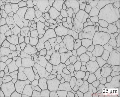
Fig. 2 Microstructure of as-received AZ31B Mg alloy
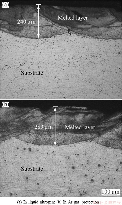
Fig. 3 Low magnified cross-sectional OM micrographs of melted layers after LSM
It can be found that both melted layers appear crescent and their refined microstructures are not uniform from surface to substrate (Figs. 4 and 5) due to the inadequate energy distribution of Gaussian distribution during laser irradiation. A very fine microstructure is observed near surface within 100 ��m (Fig. 4(a) and Fig. 5(a)), which result from consuming convection and high cooling rate of the surface. The solidification speed decreases with the increase of the layer depth, which makes dendrites coarser in deeper layer depth. At the bottom of the melted layer, spindly dendrite structures are found due to insufficient heat and relatively low cooling rate. Moreover, re-solidified microstructure grows epitaxially from the substrate due to the high temperature gradient, as shown in Fig. 4(b) and Fig. 5(b). In the middle and the upper regions, the structures of laser melted layers are obviously refined and can not be observed clearly.
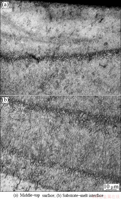
Fig. 4 Cross-sectional OM micrographs of melted layers in liquid nitrogen of AZ31B Mg alloy sample
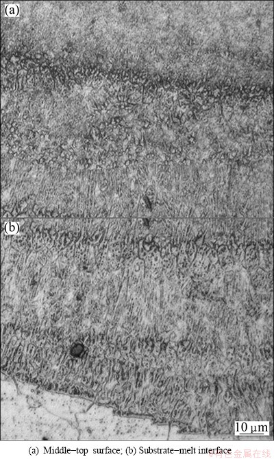
Fig. 5 Cross-sectional OM micrographs of melted layers in Ar gas protection of AZ31B Mg alloy sample
In order to obtain detailed information about the microstructural changes produced after laser treatment, a high transmission electron microscope (TEM) and high resolution transmission electron microscope (HR-TEM) were utilized. Figure 6 shows typical TEM micrographs of the melted layer (about 80 ��m in depth) of the sample in liquid nitrogen. The microstructure of melted layer is highly refined and a large number of worms-like grains form, as shown Fig. 6(a). The corresponding selected area electron diffraction (SADE) patterns exhibit entire rings. The ring-like electron diffraction pattern illustrates the formation of finer grains with a random orientation in the melted layer. Figure 6(b) shows the TEM magnification image of the white rectangle zone A in Fig. 6(a). The average length of the worm-like particles is about 200 nm and the width is about 60 nm. COY et al [20] observed that the microstructure of the melted layer by excimer laser on the die cast AZ91D magnesium alloy displayed Moir�� fringes related to the presence of a network of nanocrystallites with different crystallographic orientations and the ED pattern of the melted layer exhibited weak diffuse rings with bright spots that could be indexed according to the HCP magnesium structure. Some researches have attributed this morphology to the combined action of the stress wave and the rapid thermal cycle imparted to the material during LSM [22]. Figures 6(c) and (d) show further detailed observation of zone B and zone C in Fig. 6(b) by HR-TEM. It can be observed that zone B and zone C show disordered arrangement of atoms, which indicates that the local area forms amorphous structure, as shown by the arrows.
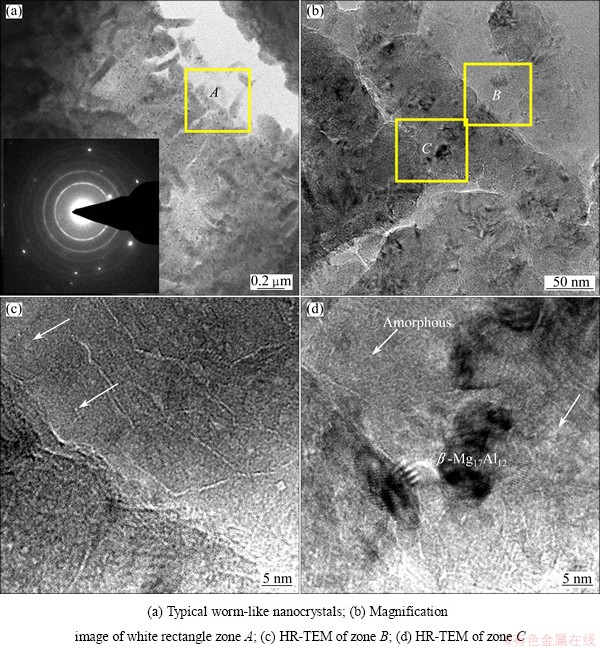
Fig. 6 TEM images of melted layer in liquid nitrogen (about 80 ��m in depth)
Based on the thermodynamics criterion of laser amorphousizing:
Tgn=Tg/Tn (1)
where Tn is the actual crystallization temperature of the undercooled melt, Tg is the glass transition temperature (the liquid structure frozen temperature). During laser rapid solidification, the solidification temperature is not Tm (melting temperature) but Tn. At high cooling rates, the atomic diffusion restructuring is the most important kinetics obstacles to prevent crystallization. Studies have shown that magnesium alloy has stronger amorphous formation ability [23]. Magnesium alloys were melted by high energy laser in liquid nitrogen and the cooling speed of local area may be equal to or higher than the formed amorphous speed. Therefore, an enough high cooling rate contributes to the formation of amorphous.
Typical TEM images of the melted layer in Ar gas protection are presented in Fig. 7 in a depth of about 80 ��m from the surface layer of the sample. A lot of cell substructures are observed and the size of the subgrains is 2-10 ��m. Some small black ball-like ��-Mg17Al12 precipitates are found inside the subgrains as shown Fig. 7(a). Moreover, a great number of stack faults (Fig. 7(b)) dislocations pile-ups (Fig. 7(c)) and dislocation wall (DW) (Fig. 7(d)) are formed inside the grains. Therefore, the inhomogenously distributed dislocations result in the formation of high dislocation density area and low dislocation density area, which is the initial stage of the subgrain.
3.2 Microhardness
The vibrations of microhardness along depth of laser melted layers are depicted in Fig. 8. It is apparent that the microhardness of laser melted layer in liquid nitrogen has significantly increased to HV 90-148 as compared to that of laser melted layer in Ar gas protection (HV 65-105). The maximum micro-hardness of the melted layer in liquid nitrogen appears near the surface and the whole change trend is larger than the latter. For the latter, the increase of microhardness is mainly due to the fine dendrites microstructure, the re-dissolution and re-distribution of ��-phase and dislocation. According to Hall-Petch equation:
��=��0+kd-1/2 (2)
where �� is the yield stress, ��0 is the yield stress of a single crystal, k is a constant and d is the grain size.
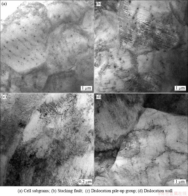
Fig. 7 Typical TEM images of laser melted layer in Ar gas protection (about 80 ��m in depth)
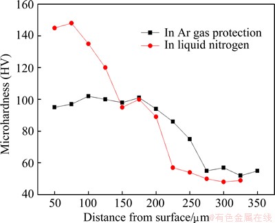
Fig. 8 Microhardness profiles along depth for laser melted layers
The improvement factors of microhardness of the melted layer in liquid nitrogen may be different with the above. Some research results indicated that the mechanical properties of nanocrystalline materials are usually much higher than its polycrystalline. Hall-Petch equation of the relationship between strength and grain size does not continue to nanoscale. This is due to that Hall-Petch formula derived from the reinforcement of dislocation. But when the grain sizes reach nanoscale, the dislocation may be less or even does not exist [24]. Therefore, the enhancement of microhardness of the melted layer in liquid nitrogen may be attributed to the changes of ��-phase morphology and distribution. In addition, local amorphous structure can also help to improve the microhardness of the melted layer.
3.3 Corrosion resistance
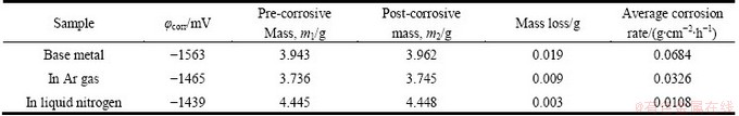
The potentiodynamic polarization curves of laser melted layers and as-received AZ31B Mg alloy are given in Fig. 9. Table 2 shows the corrosion potential, mass loss and corrosion rate of as-received AZ31B and laser melted layer. The corrosion potential of laser melted layers in liquid nitrogen is -1439 mV, which is 26 mV and 124 mV higher than those of the layers at room temperature and as-received Mg alloy substrate, respectively. The corrosion rate of melted layers in liquid nitrogen is 0.0108 g/(cm2��h), which is about 1/3 of that of the layers at room temperature. Both of the melted layers have an improved corrosion rate compared with the as-received substrate. Therefore, we can conclude that the corrosion resistance of samples in deep cryogenic treatment is improved compared with that of the samples in Ar gas protection.
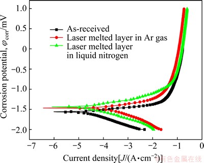
Fig. 9 Potentiodynamic polarization curves of laser melted layer and as-received AZ31B Mg alloy
MAJUMDAR et al [25] thought that the Mg corrosion mechanism consisted of two distinct stages: one is initiation of corrosion dominated by mainly galvanic corrosion and the other is propagation of corrosion dominated by pitting corrosion.
There is always a surface film on Mg and its alloys even after polishing, and the film mainly consists of magnesium oxides and hydroxides, which has been confirmed by XRD and XPS [26]. The overall corrosion reaction for pure Mg can be written as
Mg+2H2O��Mg(OH)2+H2 (3)
The magnesium hydroxide film, Mg(OH)2 though extremely protective to atmospheric corrosion, is quite responsive to electrochemical and environmental change.
Laser surface melting causes a significant grain refinement and precipitate redistribution in ��(Mg) matrix, as shown in Figs. 6 and 7. The smaller the grains, the higher the grain boundary areas, therefore more precipitates and thereby, the smaller the anode to cathode area ratio [25].
Table 2 Results of electrochemical tests
In the presence of chloride anions, a soluble magnesium salt is formed at the metal�Csolution interface by the following reaction:
Mg2++2Cl-��MgCl2+2e (4)
This soluble magnesium salt damages the protective Mg(OH)2 film. Subsequently, the exposed metal reacts afresh with the electrolyte (self-dissolution) at sites where the protective scale is breached, and thereby, increases the corrosion rate. Once the pit formation starts, it propagates at a very rapid rate [20]. From the kinetic study, it may be concluded that the rate of pit formation is slower in laser surface melted specimens than that in the as-received ones. The slower pit formation kinetics of laser surface melted specimens may be attributed to a much slower rate of degradation/ dissolution of the Mg(OH)2 film on the surface. The Mg(OH)2 film on top of laser surface melted samples in liquid nitrogen and in Ar gas protection (vis-a-vis as-received samples) are more stable because of the finer grain size of the matrix underneath and anchoring effect of grain boundary precipitates at very small intervals [27].
Furthermore, rapid solidification rate alters this microstructure, and the alumium concentration increase improves the corrosion resistance of the magnesium. With the increase of cooling rate, solid-liquid interface advances with a high speed, the long-range diffusion of the atoms is suppressed, solute atoms at the solid-liquid interface are too late to diffusion, and there is no time to exchange the solute to balance the distribution coefficient in the solid and liquid phases. Therefore, the solute atoms are captured by the solid phase, which results in that the solid solubility limit is expanded. Some studies have shown that rapid solidification processing can result in the improvement of the corrosion resistance of magnesium alloy, and with the increase of aluminum percentage in magnesium solid solution, the cooling rate and solid solubility limit also increase [28].
According to the TEM images, we can analyzed that the crystallization for some area was suppressed combined with a extremely high liquid-nitrogen assisted cooling rate, and some area formed amorphous structures. This will also help to improve the corrosion resistance. Besides, the characteristics of rapid solidification always can refine the grains of melted layer to nanoscale, and make the composition and microstructure uniform and homogenous. As a result, the covering area between cathode and anode is reduced, and the corrosion rate is reduced correspondingly. In conclusion, the cooling rate of the laser-melted layer plays an important role in microstructure transformations within the material.
4 Conclusions
1) Laser surface melting treatment of AZ31B Mg alloy in liquid nitrogen was carried out by a pulsed Nd:YAG laser. The microstructures of melted layers in liquid nitrogen are evidently refined compared with that of Ar gas protection at room temperature. A large number of worm-like grains and local amorphous structures are formed in the melted layers.
2) The microhardness test results show that the microhardness of melted layer in liquid nitrogen is increased by 40% compared with the melted layer in Ar gas protection.
3) The laser surface melting treatment of AZ31B improved the corrosion resistance in 3.5% NaCl by electrochemical test. The improved corrosion behavior is associated with a refinement in the alloy��s microstructure and the uniform distribution and formed local amorphous in liquid nitrogen.
References
[1] PAN Fu-sheng, ZHANG Jin, WANG Dong-ya. Chinese new material industrial development report on Mg and Mg alloy [M]. Beijing: Chemical Industry Press, 2004. (in Chinese)
[2] STAIGER M P, PIETAK A M, HUADMAI J, DIAS G. Magnesium and its alloys as orthopedic biomaterials: A review [J]. Biomaterials, 2006, 27: 1728-1734.
[3] ATRENS A, SONG Guang-ling, CAO Fu-yong, SHI Zhi-ming, BOWEN P K. AdvancesinMg corrosionandresearch suggestions [J]. Journal of Magnesium and Alloys,2013, 1(3): 177-200.
[4] LUO Xi-liang, XIN Yan, CUI Tracy. Electrochemical deposition of conducting polymer coatings on magnesium surfaces in ionic liquid [J]. Acta Biomaterialia, 2011, 7: 441-446.
[5] HAJIALI FINI M, AMADEH A. Improvement of wear and corrosion resistance of AZ91magnesium alloyby applying Ni-SiC nanocomposite coating via pulse electrodeposition [J]. Transactions of Nonferrous Metals Society of China,2013, 23(10): 2914-2922.
[6] SHAO Zhong-cai, CAI Zhi-qiang, HU Rong, WEI Shou-qiang. The study of electroless nickel plating directly on magnesium alloy [J]. Surface and Coatings Technology, 2014, 249: 42-47.
[7] LIU Guang-yi, TANG Sha-wei, WANG Chuan, HU Jin, LI De-chao. Formation characteristic of Ca-P coatings on magnesium alloy surface [J]. Transactions of Nonferrous Metals Society of China,2013,23(8): 2294-2299.
[8] WAN Peng, LIN Xiao, TAN Li-li, LI Lugee, LI Wei-rong, YANG Ke. Influence of albumin and inorganic ions on electrochemical corrosion behavior of plasma electrolytic oxidation coated magnesium for surgical implants [J]. Applied Surface Science, 2013, 282: 186-194.
[9] CHU Cheng-lin, HAN Xiao, BAI Jing, XUE Feng, CHU Paul-kao. Surface modification of biomedicalmagnesium alloywires by micro-arc oxidation [J]. Transactions of Nonferrous Metals Society of China,2014, 24(4): 1058-1064.
[10] ALTUN H, SEN S. The effect of PVD coatings on the wear behaviour of magnesium alloys [J]. Materials Characterization, 2007, 58: 917-921.
[11] XU Rui-zhen, YANG Xiong-bo, SUEN Kai-wong, WU Guo-song, LI Peng-hui, CHU P K. Improved corrosion resistance on biodegradablemagnesiumby zinc and aluminumion implantation [J]. Applied Surface Science, 2012, 263: 608-612.
[12] MONDAL A K, KUMAR S, BLAWERT C, DAHOTRE N B. Effect of laser surface treatment on corrosion and wear resistance of ACM720 Mg alloy [J]. Surface and Coatings Technology, 2008, 202: 3187-3198.
[13] MAJUMDAR J D, GALUN R, MORDIKE B L, MANNA I. Effectoflaser surface meltingoncorrosionandwear resistanceofa commercial magnesium alloy [J]. Materials Science and Engineering A, 2003, 361: 119-129.
[14] CUI Ze-qin, YANG Hong-wei, WANG Wen-xian, WU Hong-liang, XU Bing-she. Laser cladding Al-Si/Al2O3-TiO2 composite coatings on AZ31B magnesium alloy [J]. Journal of Wuhan University of Techonology, 2012, 27(6): 1042-1047. (in Chinese)
[15] ABBAS G, LIU Z, SKELDON P. Corrosion behaviour of laser-melted magnesium alloys [J]. Applied Surface Science, 2005, 247: 347-353.
[16] WANG Ling-qian, ZHOU Jian-song, LI Jun, CHEN Jian-min. Microstructure and corrosion behavior of plasma electrolytic oxidation coated magnesium alloy pre-treated by laser surface melting [J]. Surface & Coatings Technology, 2012, 206: 3109-3115.
[17] TALTAVULL C, TORRES B, LOPEZ A J, RODRIGO P, OTERO E, ATRENS A, RAMS J. Corrosion behaviour of laser surface melted magnesium alloy AZ91D [J]. Materials and Design, 2014, 57: 40-50.
[18] GUAN Ying-chun, ZHOU Wei, LI Zhong-li, ZHENG Hong-yu. Influence of overlapping tracks on microstructure evolution and corrosion behavior in laser-melt magnesium alloy [J]. Materials and Design, 2013, 52: 452-458.
[19] CHAKRABORTY BANERJEE P, SINGH RAMAN R K, DURANDET Y, MCADAME G. Electrochemical investigation of the influence of laser surface melting on the microstructure and corrosion behaviour of ZE41 magnesium alloy-An EIS based study [J]. Corrosion Science, 2011, 53: 1505-1514.
[20] COY A E, VIEJO F, GARCIA-GARCIA F J, LIU Z, SKELDON P, THOMPSON G E. Effect of excimer laser surface melting on the microstructure and corrosion performance of the die cast AZ91D magnesium alloy [J]. Corrosion Science, 2010, 52: 387-397.
[21] KHALFAOUI W, VALERIO E, MASSE J E, AUTRIC M. Excimer laser treatmentof ZE41magnesium alloyforcorrosion resistance and microhardness improvement [J]. Optics and Lasers in Engineering, 2010, 48: 926-931.
[22] GAO Bo, HAO Sheng-zhi, ZOU Jian-xin, WU Wen-yuan, TU Gan-feng, DONG Chuang. Effect of high current pulsed electron beam treatment on surface microstructure and wear and corrosion resistance of an AZ91HP magnesium alloy [J]. Surface and Coating of Technology, 2007, 201: 6297-6303.
[23] MATIAS T B, ASATO G H, RAMASCO B T, BOTTA W J, KIMINAMI C S, BOLFARINI C. Processing and characterization of amorphousmagnesiumbased alloy for application in biomedical implants [J]. Journal of Materials Research and Technology,2014, 3: 203-209.
[24] CHU Zhang-xiong, XIANG Jin-zhong, XU Si-yong. Scope theoretical derivation and discussion of Hall-Petch relationship [J]. Physics Examination and Testing, 2012, 30: 14-17.
[25] MAJUMDAR J D, GALUN R, MORDIKE B L, MANNA I. Effectoflaser surface meltingoncorrosionandwear resistanceofa commercial magnesium alloy [J]. Materials Science and Engineering A, 2003, 361: 119-129.
[26] PU Z,SONG G L, YANG S, OUTEIRO J C, DILLON O W Jr, PULEO D A, JAWAHIR I S. Grain refined and basal textured surface produced by burnishing for improvedcorrosionperformance of AZ31B Mg alloy [J]. CorrosionScience, 2012, 57: 192-201.
[27] TALTAVULL C, TORRES B, LOPEZ A J,RODRIGO P, OTERO E, ATRENS A, RAMA J. Corrosion behaviour of laser surface melted magnesium alloy AZ91D [J]. Materials & Design, 2014, 57: 40-50.
[28] LIU S Y, HU J D, YANG Y, GUO Z X, WANG H Y. Microstructure analysis of magnesium alloy melted by laser irradiation[ J]. Applied Surface Science, 2005, 252(5): 1723-1731.
������1,2��ʩ��ϼ1��������1,2��������1,2
1. ̫ԭ������ѧ ���Ͽ�ѧ�빤��ѧԺ��̫ԭ 030024��
2. ̫ԭ������ѧ �²��Ͻ����ѧ�빤�̽������ص�ʵ���ң�̫ԭ 030024
ժ Ҫ�������������������þ�Ͻ������Է���֮һ��Ϊ�˽�һ�����þ�Ͻ�ı������ܣ������Һ��������ȴ�뼤���������ϵķ�����ͨ���ı�þ�Ͻ�����¶ȣ��ӿ���Բ�������ٶ�������þ�Ͻ�ı������ܡ�������������������������������ȣ�Һ��������ȴ�����£�þ�Ͻ�����γ�һ��ϱ��ĸ��Բ㣬��������ϸ�����������ϱ����γ��˴��������״�����������ֲ������������ķǾ���֯������Ӳ��Ϊ HV 90~148�����������������������(Ӳ��Ϊ HV 60~105)�����Լ40%����3.5%NaCl��Һ�н��е绯ѧ���ԣ����������Һ��������ȴ�����¸��Բ����ʴ���������, ��ԭ����Ҫ�����ڿ������̹����о���ϸ�����ڶ��� ��-Mg17Al12���ٷ��估�ֲ��Ǿ���֯�ۺ����صĽ����
�ؼ��ʣ�þ�Ͻ𣻼������������Һ����ȴ����Ӳ�ȣ���ʴ����
(Edited by Yun-bin HE)
Foundation item: Project (51305292) supported by the National Natural Science Foundation of China; Project (2014-024) supported by Shanxi Scholarship Council of China
Corresponding author: Ze-qin CUI; Tel/Fax: +86-351-6010076; E-mail: cuizeqin@tyut.edu.cn
DOI: 10.1016/S1003-6326(15)63744-X

