��ѹ�����ƻ�ģʽ����ѧ�о�ģ��
��Դ�ڿ����й���ɫ����ѧ��(Ӣ�İ�)2016���10��
�������ߣ������� ɣ���� �ξ� ����� ������
����ҳ�룺2711 - 2723
�ؼ��ʣ��ƻ�ģʽ������Ӧ���������ƻ�����Ч��ת��ϵ������ѧ�о�
Key words��failure mode; inner tensile stress; tensile failure; effective conversion coefficient of energy; mechanical criteria
ժ Ҫ����ѹ�������ƻ�ģʽ��һ�ָ��ӵ���������Ϊֹ��û��һ��ͨ�õı���ѧģ���������������ǣ������������������ѹ�������ƻ�ģʽ���Է�Ϊ8�ࡣ�ڱ��о��У����ȷ�������ѹ�����ڲ�������Ӧ���Լ��ڲ������ĺ�ɢ��ת����Ȼ��������Ч��ת��ϵ������������ѹ�����������ƻ����Mohr-Coulomb�����ƻ���������ѹ����������-�����ƻ����ɴ˽�������ѹ�����ƻ�ģʽ����ѧ�о�ģ�ͣ���ģ�Ϳ��Ժܺõؽ����������ͱ��о�����ѹ�������ƻ�ģʽ�Լ����������Ȼ����
Abstract: The failure modes of rock and soil under compression are complex phenomena that have not been explained in a mechanical perspective. However, large amounts of studies indicate that the failure modes of rock and soil samples can be categorized into eight types. In this work, the inner tensile stress and the dissipation and conversion of energy of rock and soil under compression are analyzed, then the effective conversion coefficient of energy is deduced, thus the tensile failure criterion of rock and soil under compression is established. Combined with the shear strength criterion of Mohr�CCoulomb, a tensile joint shear strength criterion for rock and soil under compression is built. Therefore, a mechanical criterion model concerning the failure modes of rock and soil under compression is established and verified by tests. This model easily explains the test results in the existing literature and many natural phenomena, such as collapse.
Trans. Nonferrous Met. Soc. China 26(2016) 2711-2723
Lian-sheng TANG1, Hai-tao SANG2,3, Jing SONG1, Zhen-gui LUO1, Yin-lei SUN1,3
1. School of Earth Sciences and Geological Engineering, Sun Yat-Sen University, Guangzhou 510275, China;
2. School of Engineering, Sun Yat-Sen University, Guangzhou 510275, China;
3. Guangdong Provincial Key Laboratory of Geological Processes and Mineral Resource Survey, Guangzhou 510275, China
Received 6 September 2015; accepted 22 March 2016
Abstract: The failure modes of rock and soil under compression are complex phenomena that have not been explained in a mechanical perspective. However, large amounts of studies indicate that the failure modes of rock and soil samples can be categorized into eight types. In this work, the inner tensile stress and the dissipation and conversion of energy of rock and soil under compression are analyzed, then the effective conversion coefficient of energy is deduced, thus the tensile failure criterion of rock and soil under compression is established. Combined with the shear strength criterion of Mohr�CCoulomb, a tensile joint shear strength criterion for rock and soil under compression is built. Therefore, a mechanical criterion model concerning the failure modes of rock and soil under compression is established and verified by tests. This model easily explains the test results in the existing literature and many natural phenomena, such as collapse.
Key words: failure mode; inner tensile stress; tensile failure; effective conversion coefficient of energy; mechanical criteria
1 Introduction
The failure modes of rock and soil under compression are complex phenomena that have not been explained in a standard mechanical model. However, for years, a large quantity of experimental studies have shown that the compression failure of rock and soil under uniaxial and triaxial tests can be divided into five modes: splitting failure, tensile shear failure, shear failure, dilatancy failure and bulging failure as illustrated by Figs. 1(a), (b), (c), (d) and (e), respectively. Though the pure tensile failure under axial extension as illustrated by Fig. 1(f) is possible, the geotechnical material under axial extension is also likely to rupture in the shear fracture mode as illustrated by Fig. 1(g) and the hybrid fracture mode as illustrated by Fig. 1(h) [1].
Why do these peculiar phenomena exist? Neither historical nor modern theories can fully describe the failure patterns, although many researchers have tried to study the mechanism from the influencing factors such as confining pressures, material composition, brittleness and ductility of the samples, and fissures. The study of confining pressures impacting the failure modes of rock and soil is enduring. TAYLOR [2] found that, in conventional triaxial compression tests, loose sand deformed mainly via drum-shaped deformation, yet dense sand failed via shear surfaces. From then on, more and more experiments prove that the failure modes of undisturbed and remoulded soil samples under low confining pressures should be strikingly different from those under high confining pressures. Undisturbed soil fails via shear surfaces under low confining pressures, whereas it deforms via tension deformation under high confining pressures [3-6]. In contrast, regardless of the confining pressure, disturbed and remolded samples deform via drum-shaped (tensile) deformation [3-7]. For example, the failure shape of the foamed particle light mass soil sample is in the form of a drum under a low confining pressure and a shear zone is observed, whereas the failure shape is a contraction without a shear zone under a high confining pressure. However, the study of the impact of material composition of rock and soil on its failure modes rises gradually in nearly 10 years [8,9] and the achievement is less. It is a remarkable fact that there are increasing researchers [10] noting the failure modes of rock and soil having a close relationship with their brittleness and ductility, which is also a focus of this work. The experiments and numerical simulations by HE [11], WU et al [12], LIU [13] and MORA et al [14] proved that the failure modes of rock and soil have a close relationship with its brittleness and ductility. Moreover, the fissures of geo-materials always have a governing impact on its failure modes [15,16]; however, we just discuss homogeneous isotropic rock and soil in this work, without considering the effect of fissures. In summary, we can discover that there are so many qualitative inquiries into this field from the perspective of the influencing factors, but the mechanics criterion of the failure mode of rock and soil under compression is still unknown.
The aim of this work is to give a mechanical expiation and model for the failure modes of rock and soil under compression, not meaning there is just one model. We believe that the model established in this work can simply explicate and determine which failure mode the rock and soil have, and it can not only explain many phenomena in the mechanics tests of rock and soil, such as dilatancy, but also explain natural phenomena that the failure model of landslide characterized by shear failure often occurs in ductile rock and soil mass, and collapse characterized by tensile failure often occurs in brittle rock and soil mass under the action of gravity; however, the landslide characterized by shear failure also possibly occurs in brittle rock and soil mass when the confining pressure and overlying load are large.
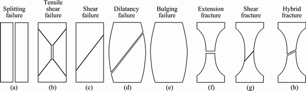
Fig. 1 Eight failure modes of rock and soil under compression
2 Stress and energy analysis in triaxial compression
As illustrated by Fig. 2, in the triaxial compression stress state ��1�ݦ�2�ݦ�3, assuming that the triaxial test sample is a square block with height h and width b, h=2b, a complex inner stress field ��(x, y, z) is produced in geotechnical materials under the action of compressive stress ��1, and normal stress and shear stress are produced due to this inner stress field. Assume that the produced normal stress in the x direction is ��1x(x, y, z) and the produced normal stress in the y direction is ��1y(x, y, z).
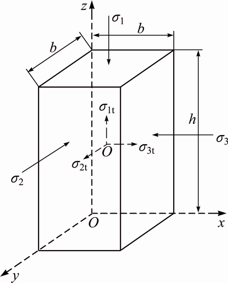
Fig. 2 Square cylinder under triaxial stress state
For static equilibrium in the x direction, the equilibrium equation can be expressed as
 (1)
(1)
That is
 (2)
(2)
According to the symmetry, it can be easily known that
 (3)
(3)
Assuming
 (4)
(4)
Therefore, there are two equal and opposite inner tensile stresses, ��13t, symmetrical distributing in the x direction about x=b/2. Accordingly, applying this principle to the y direction, there are two equal and opposite inner tensile stresses, ��12t, symmetrical distributing in the x direction about y=b/2. This well agrees with the results by TANG [17] that there will be inner tensile stress in rock and soil due to the outer compressive stress, which indirectly proves the above derivation.
Assuming that the compressive stress ��1 acting on the square block sample in triaxial test produces axial displacement ��1, generating lateral displacement ��12/2 in the direction of ��2 and �C��2 and lateral displacement ��13/2 in the direction of ��3 and �C��3 as illustrated by Fig. 2. Because the geo-material is not an ideal elastic material, some inputting energy of geotechnical materials under the compressive stress ��1 is dissipated through plastic deformation, including micro-crack closure, internal friction and flaw evolution, and this dissipation energy, Qd, is dissipated and is not converted into the vertical and lateral deformation energy. According to the energy conservation law, there is
 (5)
(5)
where ��12t and ��13t are respectively the inner tensile stresses in the directions of ��2 and ��3.
Equation (5) can be written as follows:
 (6)
(6)
where �� is the effective conversion coefficient of energy, having a close relationship with the brittleness and ductility of the geo-material, indicating the percent of the inputting energy into the samples converting into the energy consumed by the vertical and lateral deformation, 0�ܦΡ�1. When ��=0, it indicates that all the inputting energy into the samples is dissipated by the processes such as micro-crack closure, internal friction and flaw evolution, not converted into the vertical and lateral deformation. When ��=1, it indicates that all the inputting energy into the samples is converted into the vertical and lateral deformation, at this moment, Eq. (5) is just the Betti theorem in elastic mechanics [17].
Equation (6) can be simplified as follows:
 (7)
(7)
where v is the Poisson ratio of rock and soil materials.
The same effect on the inner tensile stresses (��23t and ��21t) by the stress of ��2 in the directions of ��3 and ��1 and the inner tensile stresses (��32t and ��31t) by the stress of ��3 in the directions of ��2 and ��1 can be obtained by the following formulas:
 (8)
(8)
 (9)
(9)
Thus, the inner tensile stresses ��1t, ��2t and ��3t produced by compressive stresses ��1, ��2 and ��3 in the direction of principal stresses are shown as follows:
 (10)
(10)
 (11)
(11)
 (12)
(12)
Geotechnical material mechanics experiments show that, compared with ductile materials, the Poisson ratio of brittle materials is smaller [18]. Equations (8)-(12) demonstrate that the inner tensile stress of brittle materials is greater than that of ductile materials.
In the triaxial compression stress state ��1�ݦ�2�ݦ�3, when the inner tensile stress ��3t, produced by compressive stresses ��1 and ��2 in the direction of principal stress ��3, plus the compressive stress ��3, is equivalent to the tensile strength ��tf, a geotechnical material will be damaged, as shown in Eq. (13). In the triaxial extension stress state ��1�ܦ�2�ܦ�3, when the inner tensile stress ��1t, produced by the compressive stresses ��2 and ��3 in the direction of the principal stress ��1, plus the compressive stress ��1, is equivalent to the tensile strength ��tf, a geotechnical material will be damaged, as shown in Eq. (14).
In triaxial stress state ��1�ݦ�2�ݦ�3,
��3t-��3-��tf=0 (13)
In triaxial stress state ��1�ܦ�2�ܦ�3,
��1t-��1-��tf=0 (14)
Substituting Eqs. (10), (11) and (12) into Eqs. (13) and (14) yields the following equations:
In triaxial stress state ��1�ݦ�2�ݦ�3,
 (15)
(15)
In triaxial stress state ��1�ܦ�2�ܦ�3,
 (16)
(16)
When rock and soil samples are in a critical state of uniaxial compression, ��1>0, ��2=��3=0, Eq. (15) can be simply written as follows:
 (17)
(17)
where
��1=��cf (18)
where ��cf is the uniaxial compressive strength of geotechnical materials.
Substituting Eq. (18) into Eq. (17) produces the following equation:
 (19)
(19)
When rock and soil samples are in the critical state of biaxial tension and compression stress, ��1 is the compressive stress (the value of ��1 is positive), ��2=0, and ��3 is the tensile stress (the value of ��3 is negative). Thus, Eq. (15) can be written in the following simple form:
 (20)
(20)
Both sides of Eq. (20) are divided by ��tf, and the equation is combined with Eq. (19), yielding
 (21)
(21)
Equation (21) happens to be the theory formula of the failure criterion of brittle rock and concrete under biaxial tension and compression, which is consistent with the test results of a large number of brittle materials, such as rock and concrete [19-21]. This equation is applied in general engineering. This formula is also adopted in the Japanese Dam Design Code (1978 revised edition). Hence, Eq. (21) could reflect the deformation characteristics of brittle materials, such as concrete and rock, which also indirectly proves the inner tensile stress theory in this paper used to analyze the deformation characteristics of geotechnical materials.
3 Mechanical failure criteria and model
Using the lode angle ��, the second invariant of the stress deviator (the second deviatoric stress tensor invariant) J2 and the first invariant of main stress deviator (the first principal stress invariants) I1, Eqs. (15) and (16) can be combined as follows:
 (22)
(22)
where  .
.
The general formula of Eq. (22) for the yield condition is as follows:
 (23)
(23)
Equations (22) and (23) are the tensile failure criteria of geotechnical materials under a triaxial stress state. If Eq. (22) is not valid, the equation shows that the inner tension stress has become greater than or equal to the tensile strength when shear failure occurs or that shear failure has occurred before tensile failure occurs. Otherwise, only shear failure will have occurred in the samples.
The strength criterion of Mohr-Coulomb belongs to the single shear angle of the shear failure criterion, which shows that the shear strength is related to the normal stress applied on the plane. The combination ��-�� on the plane (rather than the maximum shear stress) is the most dangerous situation because it causes material damage. Its negative half-shaft is often equivalent to the tensile failure criterion, which is not strict tensile failure criterion, and in fact the destruction in the negative half-shaft is still a shear failure mode. The strength criterion of Mohr-Coulomb is represented as follows:
 (24)
(24)
where  is the internal friction angle.
Thus, Eqs. (23) and (24) are just the tensile joint shear strength criteria of geotechnical material under compression. They indicate that the deformation mode of geotechnical materials is represented by only three failure modes: shear failure, tension failure or (coexistence) hybrid failure. With Eqs. (19) and (20), the yield curve on the �� plane and the yield surface in principal stress space can be determined by tensile failure and Mohr-Coulomb failure, respectively. However, determining the type of failure mode that actually occurs in a geotechnical material requires further concise criterion.
With Eqs. (23) and (24), the distance from the cone point of the tensile failure yield surface (an equilateral triangle cone surface) to the origin of coordinates  and the distance from cone point of the Mohr-Coulomb failure yield surface (an irregular hexagon cone surface) to the origin of coordinates
  are calculated respectively as follows:
 (25)
(25)
 (26)
(26)
is determined by the tensile strength of materials ��tf, Poisson ratio �� and stress conversion coefficient ��, whereas is determined by the cohesion c and internal friction angle .
If r�� represents the deviator stress of the tensile yield curve and r���� represents the deviator stress of the Mohr-Coulomb shear yield curve on the �� plane and  , then r�� and r���� are calculated respectively as follows:
 (27)
(27)
 (28)
(28)
With Eqs. (27) and (28), assuming a triaxial stress state, the value r�� is determined by the material tensile strength ��tf, Poisson ratio �� and stress conversion coefficient ��, whereas r���� is determined by the material��s cohesion c and internal friction angle .
Compared with r�� and r����, the mechanical model for the failure modes of rock and soil materials under compression is given as follows:

 (29)
(29)
where

 ,
,

In the stress state of a conventional triaxial compression test (��1�ݦ�2=��3), the lode angle is ��=-30�� and  . In the stress state of a conventional triaxial extension test (��1�ܦ�2=��3), the lode angle is ��=30�� and
  .
.
Equation (29) is the mechanical model for the failure modes of rock and soil under compression. It should be noted that Eq. (29) is just the mechanical model of geotechnical materials when deformation occurs; whether geotechnical material damage occurs depends on whether the rule of the tensile joint shear strength criterion (Eq. (25)) is met.
According to Eq. (29), the mechanical model for the compression failure mode of rock and soil is co-determined by ��, �� and ��. Among these parameters, the parameter �� is primarily determined by the internal friction angle . The parameter �� is co-determined by the average stress level (confining pressure) I1, Poisson ratio ��, the stress conversion coefficient ��, the cohesion c, the internal friction angle and the tensile strength ��tf, which is complex. However, �� depends mainly upon the curve of ��-�� when the confining pressure is low, and its value tends to be 1 when the confining pressure is high. The parameter �� is primarily determined by the curve of ��-��. This means that the geotechnical material failure mode is not only determined by the internal causes such as shear strength parameters (e.g., c and ) and tensile strength ��tf, but also by external causes such as the stress level and confining pressure. All of these factors will affect the compressive failure mode of geotechnical material.
In the conventional triaxial compression stress state (��1�ݦ�2=��3), differentiating K with respect to internal friction angle yields:
 (30)
(30)
Thus, there is stagnation point, 0, which means for internal friction angles of <0, the larger the internal friction angle is, the larger the K is, and the more the tension failure tends to occur. For internal friction angles of ��0, the larger the internal friction angle is, the smaller the K is, and the more the shear failure tends to occur.
In the conventional triaxial extension stress state (��1�ܦ�2=��3), differentiating K with respect to internal friction angle produces
 (31)
(31)
Thus, there is a stagnation point, ��0, which means for internal friction angles of <��0, the larger the internal friction angle is, the larger the K is, and the more the tension failure tends to occur. For internal friction angles of ����0, the larger the internal friction angle is, the smaller the K is, and the more the shear failure tends to occur.
Differentiating K with respect to cohesion c produces,  K/c>0, which indicates that the larger the cohesion value c is, the larger the K is, and the more the tension failure tends to occur.
Differentiating K with respect to Poisson ratio �� produces, K/��>0, which indicates that the smaller
Poisson ratio �� is, the larger K is, and the more tension failure tends to occur. This relationship means that more brittle materials tend to experience more tension failures.
Differentiating K with respect to the stress conversion coefficient �� produces K/��>0, which indicates that the larger the stress conversion coefficient �� is, the larger the K is, and the more the tension failure tends to occur. This relationship means that the more lateral tensile strain energy that is converted from longitudinal compression strain energy is, the more the tension failure tends to occur.
Under certain stress states (��1, ��2, ��3), as shown in Fig. 3(a), when the shear strength (c, ) is constant, as Poisson ratio �� increases or the stress conversion coefficient �� decreases, K decreases. Therefore, on the �� plane, the tensile yield curve will spread out, possibly leading to a shear yield line located inside the tensile yield curve. In this case, the rock or soil will experience shear failure. In contrast, when Poisson ratio �� decreases or the stress conversion coefficient �� increases, K increases. On the �� plane, the tensile yield curve will shrink, possibly shifting the location of the shear yield curve outside of the tensile yield curve. In this case, tensile failure occurs in rock and soil. During this process, three contacts (the inner contact, the intersection and the outer contact) will occur, which indicates the existence of two hybrid failure modes (the shear dilatancy zone and the tensile shear zone). As shown in Fig. 3(b), when parameters �� and �� are constant, as the angle of internal friction increases or cohesion c decreases, K decreases. Therefore, on the �� plane, the tensile yield curve will spread out, possibly leading to the shear yield line being located inside the tensile yield curve. In this case, rock and soil will experience shear failure. In contrast, as the angle of internal friction decreases or cohesion c increases, K increases. On the �� plane, the tensile yield curve will shrink, possibly shifting the location of the shear yield curve to the outside of the tensile yield curve. In this case, tensile failure occurs in rock and soil. During this process, three contacts (the inner contact, the intersection and the outer contact) will occur, indicating the existence of two hybrid failure modes (the shear dilatancy zone and the tensile shear zone).
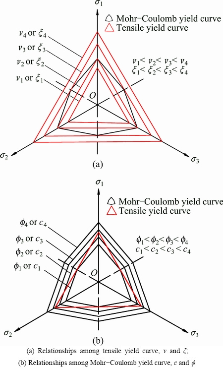
Fig. 3 Tensile yield curve and Mohr-Coulomb yield curve on �� plane
Tensile strength tests show that the tensile strength of rock and soil materials is in accordance with the relationship ��tf and
and  . This question can be answered with r�� and r���� (i.e., K can be greater than, less than or equal to 1) according to Eqs. (22) and (23). The value of K is affected by Poisson ratio �� according to Eq. (27), which is greatly influenced by the confining pressure. Thus, the tensile failure envelope is a curve rather than a straight line on the meridional plane, which is different from the Mohr-Coulomb yield curve (a six-sided conical surface, shown in Fig. 4(a). In terms of soft (or loose) rock and remolded soil, their Poisson ratios are larger. However, they will decrease as the brittleness of the soft (or loose) rock and remolded soil increases with the increasing confining pressure. Hence, the tensile yield surface is rendered as a convex trilateral conical surface, as illustrated by Fig. 4(a). In terms of hard rock and undisturbed soil, however, the Poisson ratio �� increases as the brittleness decreases with increasing confining pressure. Thus, the tensile yield surface produces a concave trilateral conical surface, as illustrated by Fig. 4(b).
Under a certain stress path, the failure mode of a geotechnical material may always change with its stress state. In terms of soft (or loose) rock and remolded soil, its Poisson ratio is larger and its stress conversion coefficient �� is smaller; thus, ��/(��-��)��cot (i.e., �͡�[cot/(cot-sin)]��) can be more easily satisfied, i.e., ��. Hence, the cone point of the tensile yield surface is usually inside the Mohr-Coulomb yield surface. However, the generatrix slope of the tensile yield surface is larger than of the Mohr-Coulomb yield surface, and the tensile yield surface shifts out from the Mohr-Coulomb yield surface at high confining pressures due to Poisson ratio ��, which is influenced by the confining pressure. Therefore, two crossing areas induced by the tensile yield surface and the classic Mohr-Coulomb yield surface are apparent in Fig. 5(a). In this case, as the confining pressure changes from low to high, there are three types of failure modes for geotechnical materials, as shown in Table 1. In terms of hard rock and undisturbed soil, the Poisson ratio is smaller and the stress conversion coefficient �� is larger; thus, ��/(��-��)��cot (i.e., �͡�[cot/(cot-sin)]��) can be more easily satisfied, i.e., >. Hence, the cone point of tensile yield surface is usually outside of the Mohr-Coulomb yield surface. However, the generatrix slope of the tensile yield surface is smaller than that of the Mohr-Coulomb yield surface, and the tensile yield surface shifts into Mohr-Coulomb yield surface at high confining pressures due to Poisson ratio ��, which is influenced by the confining pressure. Therefore, two crossing areas induced by the tensile yield surface and the classic Mohr-Coulomb yield surface are apparent in Fig. 5(b).
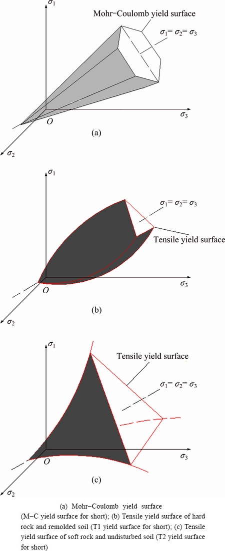
Fig. 4 Tensile yield surface and Mohr-Coulomb yield surface in principal stress space
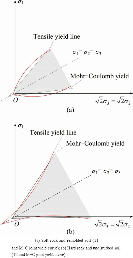
Fig. 5 Tensile yield curve and Mohr-Coulomb curve surface on central meridional plane
Table 1 Failure modes of soft rock and remolded soil (T1+M-C) with increasing first principal stress invariants I1
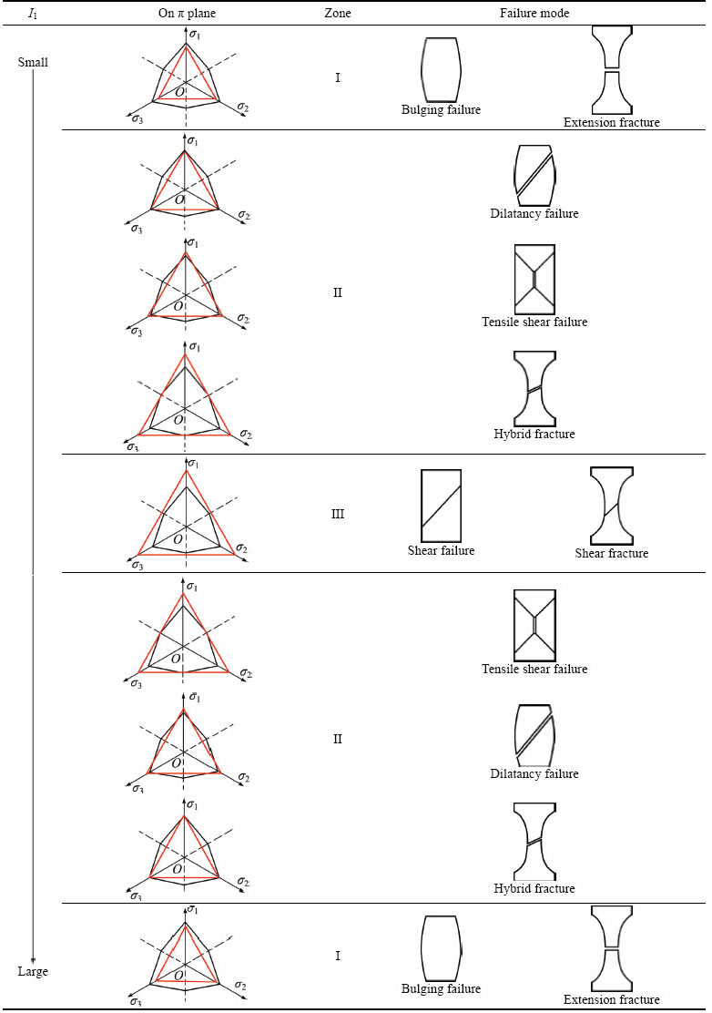
As shown in Table 1, we propose three types of failure zones of geotechnical materials, such as soft rock and remolded soil, as the first principal stress invariant I1 increases. Furthermore, failure zones are represented by two different conditions: 1) In a stress state of triaxial compression (��1�ݦ�2�ݦ�3), the low confining pressure stress area (mostly �C��3) is a tensile failure zone (Zone I). The medium confining pressure stress area is a shear failure zone (Zone III). The high confining pressure stress area is a tensile failure zone (Zone I). The overall shift out of or into the Mohr-Coulomb hybrid failure zone, which starts from the tensile yield surface, is called a tensile shear zone (Zone II) or a dilatancy failure zone (Zone II). 2) In a stress state of triaxial extension (��1�ܦ�2�ܦ�3), the low and medium confining pressure stress areas are extension fracture zones (Zone I). The medium confining pressure stress area can also be a shear fracture zone (Zone III). The high confining pressure stress area is an extension fracture zone (Zone I). Finally, the overall shift out of or into the Mohr-Coulomb hybrid fracture zone, which starts from the tensile yield surface, is a hybrid fracture zone (also Zone II) or an extension shear fracture zone (Zone II).
As shown in Table 2, three types of failure zones of geotechnical materials are proposed, such as hard rock and undisturbed soil, as the first principal stress invariants I1 increases. Furthermore, failure zones are represented in two different conditions. 1) In a stress state of triaxial compression (��1�ݦ�2�ݦ�3), the low confining pressure stress area (mostly �C��3) is a shear failure zone (Zone III). The medium confining pressure stress area is a tensile failure zone (Zone I). The high confining pressure stress area is a shear failure zone (Zone III). The overall shift out of or into the Mohr-Coulomb hybrid failure zone, which starts from the tensile yield surface, is a tensile shear zone (Zone II) or a dilatancy failure zone (Zone II). 2) In a stress state of triaxial extension (��1�ܦ�2�ܦ�3), the low and medium confining pressure stress areas are shear fracture zones (Zone I). The medium confining pressure stress area is an extension fracture zone (Zone III). The high confining pressure stress area is a shear fracture zone (Zone I). Finally, the overall shift out of or into the Mohr-Coulomb hybrid fracture zone, which starts from the tensile yield surface, is a hybrid fracture zone (Zone II) or an extension shear fracture zone (Zone II).
4 Experiments and verification
Confirmatory tests are conducted to verify the mechanical model for the failure modes of rock and soil under compression. The soil sampling site is located in a construction site in Zhuhe Town, Zengcheng District, Guangzhou City, China. The sampled soil is a granitic residual soil, whose original rock structure is quite clear and whose particle size is relatively uniform. The quartz sand content presents 10%-15%, and when the soil is slightly wet, the soil achieves a plastic-hard plastic state. A stress- and strain-controlled triaxial shear penetration test instrument, SLB-1 style, was employed to perform consolidation drainage (CD) tests indoors to investigate the failure modes of the granitic residual soil under compression with various confining pressures, dry densities, cohesions and internal friction angles.
In this validation testing, four types of samples with different parameters are used. The specific processes are as follows. 1) Undisturbed soil: the granitic residual soil clods are put in the middle of a soil cutting disc and are carefully cut to a specific diameter via a steel wire cutter or geotechnical knife close to the side panel while the disc rotates. After smoothing both ends in accordance with the height requirements, the prepared soil samples were put in the saturator. 2) Remolded soil: wet soil corresponding to a specific moisture content is used for the remolded soil, and the hierarchical compaction law is adopted. 3) Remolded clay mixed with soil: the percentage of silica sand relative to original soil (dry mass) is 25%. The silica sand particle size range is 0.25-0.30 mm, and the sand is sufficiently stirred to be evenly dispersed in the soil. Then, the hierarchical compaction law is adopted for soil samples. 4) Remolded clay mixed with cement: the percentage of added cement relative to original soil (dry mass) is 2.5%. After saturation, these samples are wrapped with plastic film and cured for 7 d in a maintenance cylinder to ensure that the cement is fully hydrated.
Triaxial consolidation drainage tests (CD) are performed according to the steps stipulated in Soil Test Procedures (L237-1999). Throughout the whole test process, the axial stress, confining pressure, axial strain and volumetric strain of soil samples are recorded. The controlled shear rate is 0.1%/min, and the controlled strain at the end of the test is 15%.
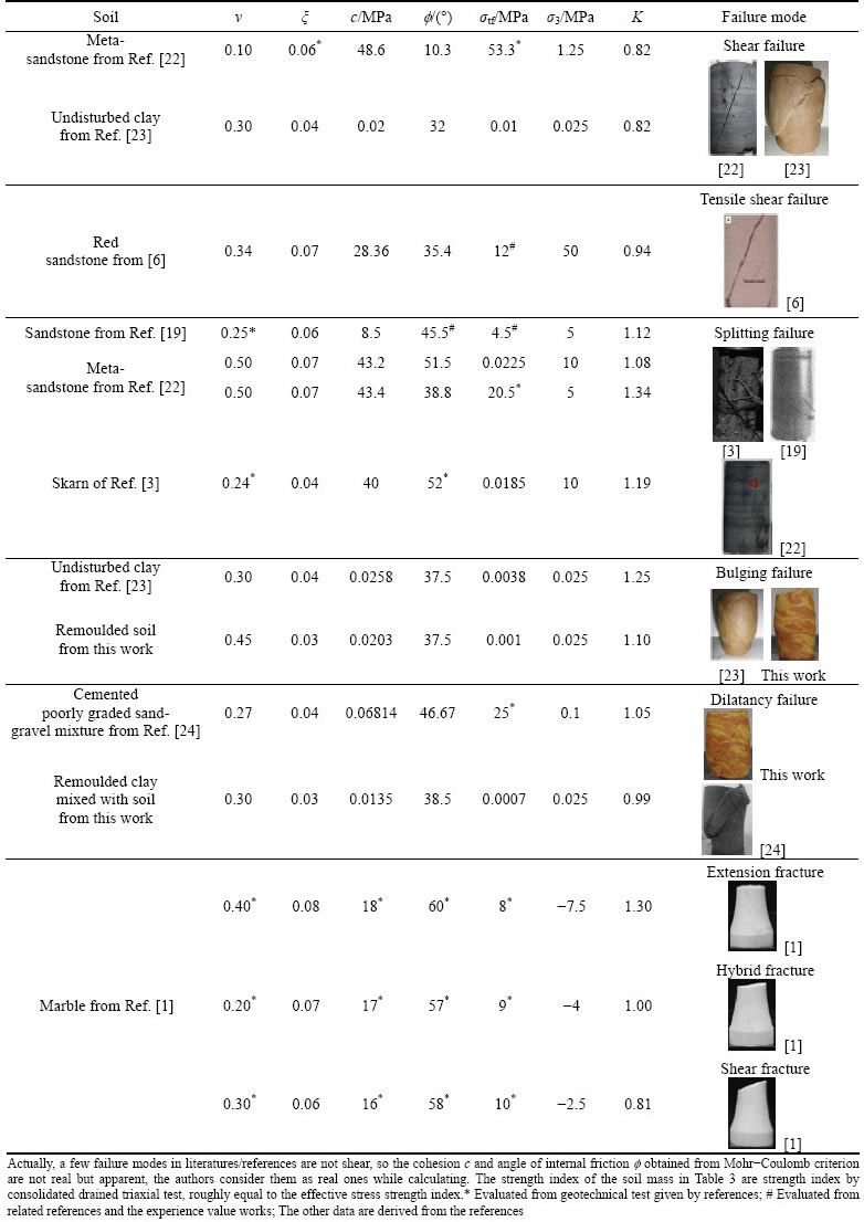
Furthermore, based on the parameters of the rock or soil samples from the existing literature and with a reasonable effective conversion coefficient of energy ��, the test data are arranged as shown in Table 3, some references cited earlier are not listed because the authors did not provide experimental photos of rock and soil samples. The failure modes (patterns) of rock and soil samples obtained by the theory in this work easily explain the test results, as well as those in the existing literature.
5 Conclusions
1) The failure modes of rock and soil samples are complex phenomena but can be categorized into eight types in this work. The effective conversion coefficient of energy is introduced on the basis of analyzing the inner tensile stress field and the compression energy��s dissipation and conversion, thus the quantitative formulas for the inner tensile stress in the other two directions, which is transformed from the compressive stress, are deduced. Then, the tensile failure criterion of geotechnical materials is established. Thus, the mechanical model for the failure modes of rock and soil under compression, which combines with the shear strength criterion of Mohr�CCoulomb, is established and can easily explain the failure patterns of rock and soil samples in the experiments and in the existing literature.
Table 2 Failure modes of hard rock and undisturbed soil (T2+M-C) with increasing first principal stress invariants I1
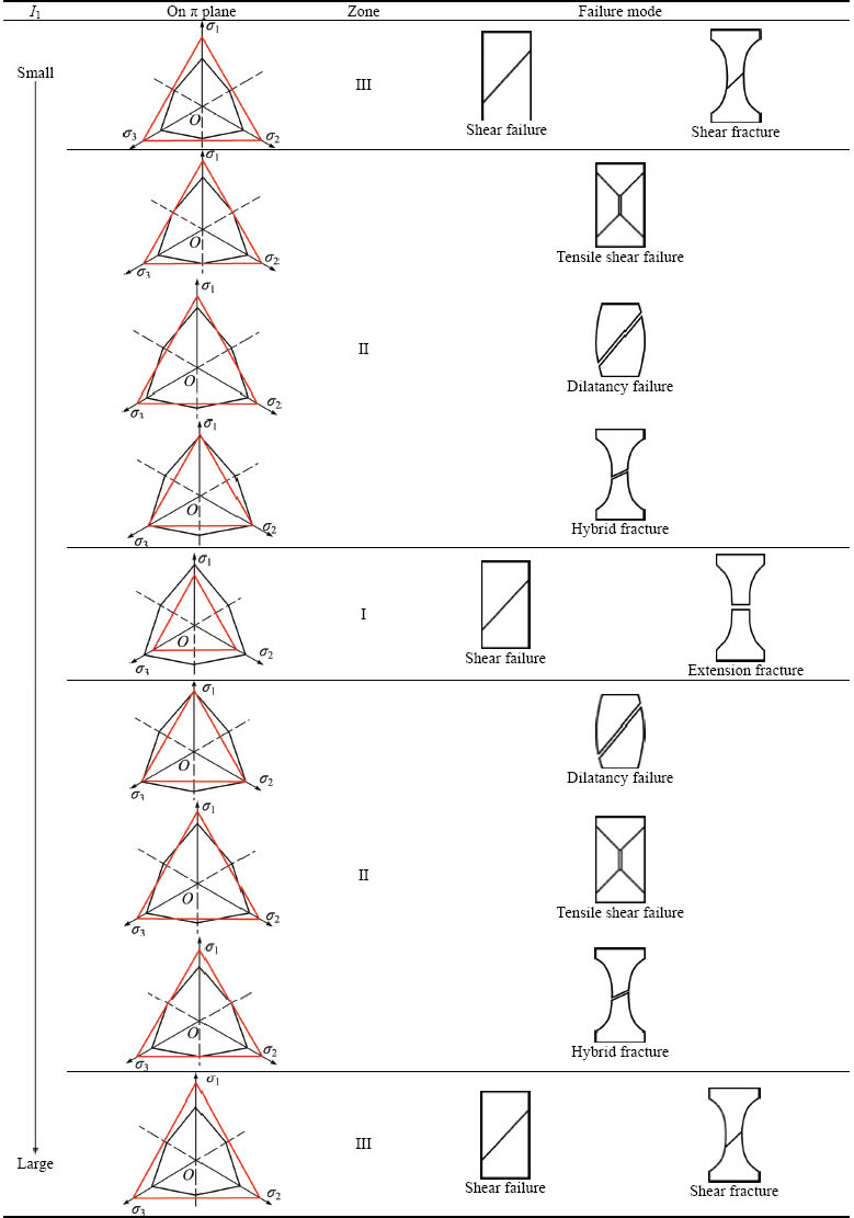
Table 3 Theoretical explanation for failure mode in geotechnical test according to mechanical model in this work
2) The quantitative formulas of the inner tensile stress in the other two directions (transformed from the compressive stress) are established through the analysis of the inner tensile stress field based on the energy��s dissipation and conversion in the process of compression. The existing theory formula for the failure criterion of concrete under biaxial tension and compression is only a special case.
3) Shear failure and tension failure can co-exist at the same time in the rock and soil samples in the process of compression. The failure modes (shear failure, tensile failure or hybrid failure) depend on whether the stress state of the geotechnical materials first meets the Mohr-Coulomb yield criterion, the tensile failure criteria or both at almost the same time based on the tensile joint shear strength criterion established in this work, which can be simply determined by the mechanical criterion set up for the failure modes of rock and soil under compression.
4) The failure modes of rock and soil under compression are complex phenomena, which are influenced by various factors. The aim of our work is to give a mechanical explanation for the failure modes of rock and soil under compression, not meaning there is just one mechanical model. However, the model established in this work can well explain the eight failure modes, thus it may inspire other researchers to give further insight into theses complex phenomena.
References
[1] JONATHAN M R, FREDERICK M C. Hybrid fracture and the transition from extension fracture to shear fracture [J]. Nature, 2004, 428(6978): 63-66.
[2] TAYLOR D W. Fundamentals of soil mechanics [M]. New York: Wiley, 1948.
[3] LI Di-yuan. Study on the brittle spalling failure of hard rock and the mechanism of strain burst under high in-situ stresses [D]. Changsha: Central South University, 2010. (in Chinese)
[4] XIAO Jing-jing. Experimental study on structural property and stress-strain relationship of granite residual soil [D]. Guangzhou: South China University of Technology, 2012. (in Chinese)
[5] ZHAO Zeng-hui, WANG Wei-ming, DAI Chun-quan, YAN Ji-xing. Failure characteristics of three-body model composed of rock and coal with different strength and stiffness [J]. Transactions of Nonferrous Metals Society of China, 2014, 24(5): 1538-1546.
[6] YANG S Q, JING H W, WANG S Y. Experimental investigation on the strength, deformability, failure behavior and acoustic emission locations of red sandstone under triaxial compression [J]. Rock Mechanics and Rock Engineering, 2012, 45(17): 583-606.
[7] DU Kun, LI Xi-bing, LI Di-yuan, WENG Lei. Failure properties of rocks in true triaxial unloading compressive test [J]. Transactions of Nonferrous Metals Society of China, 2015, 25(2): 571-581.
[8] FENG X T, CHEN S, ZHOU H. Real-time computerized tomography (CT) experiments on sandstone damage evolution during triaxial compression with chemical corrosion [J]. International Journal of Rock Mechanics and Mining Sciences, 2004, 41(3): 181-192.
[9] JING H M, ZHANG H, LI H, YUEN D A, SHI Y L. Parallel numerical analysis on the rheology of the Martian ice-rock mixture [J]. Journal of Earth Science, 2011, 22(2): 176-181.
[10] NYGARD N, GUTIERREZ M, BRATLI R K, HOEG K. Brittle-ductile transition, shear failure and leakage in shales and mudrocks [J]. Marine and Petroleum Geology, 2006, 23(2): 201-212.
[11] HE Guang-ling. New catastrophe theory and its application in pile foundation engineering [J]. Engineering Mechanics, 2009, 26(9): 126-130. (in Chinese)
[12] WU Fa-quan, WU Jei, QI Sheng-wen. Theoretical analysis on mechanism of rock burst of brittle rock mass [J]. Journal of Engineering Geology, 2010, 18(5): 589-595. (in Chinese)
[13] LIU Pei-sheng. Analysis of shearing failure mode for porous materials under compression [J]. Acta Physica Sinica, 2010, 59(7): 4849-4856. (in Chinese)
[14] MORA P, WANG Y C, MARROQUIN F A. Lattice solid/Boltzmann microscopic model to simulate solid/fluid systems-a tool to study creation of fluid flow networks for viable deep geothermal energy [J]. Journal of Earth Science, 2015, 26(1): 11-19.
[15] FENG Zeng-chao, ZHAO Yang-sheng. Control effect of fissure scale on deformation and failure of rock mass [J]. Chinese Journal of Rock Mechanics and Engineering, 2008, 27(1): 78-83. (in Chinese)
[16] WANG S Y, SLOAN S W, SHENG D C, YANG S Q, TANG C A. Numerical study of failure behaviour of pre-cracked rock specimens under conventional triaxial compression [J]. International Journal of Solids and Structures, 2014, 51(2): 1132-1148.
[17] TANG Hui-ming. Progress in study of fracture mechanism of jointing [J]. Geological Science and Technology Information, 1991, 20(2): 17-25. (in Chinese)
[18] WU Jia-long. Elasticity [M]. Beijing: Higher Education Press, 2001. (in Chinese)
[19] YANG Sheng-qi, JIANG Yu-zhou. Triaxial mechanical creep behaviour of sandstone [J]. Mining Science and Technology, 2010, 20(3): 339-349.
[20] GUO Zheng-hai, WANG Chuan-zhi. Investigation on the strength and failure criterion of concrete under multi-axial stresses [J]. China Civil Engineering Journal, 1991, 24(3): 1-14. (in Chinese)
[21] QIN Li-kun, SONG Yu-pu, CHEN Hao-ran, WANG Lie-dong, ZHANG Zhong, YU Chang-jiang. Mechanical property and failure criterion of concrete under biaxial tension and compression after freeze-thaw cycling [J]. Chinese Journal of Rock Mechanics and Engineering, 2005, 24(10): 1740-1745. (in Chinese)
[22] LI D Y, WONG L N Y, LIU G, ZHANG X P. Influence of water content and anisotropy on the strength and deformability of low porosity meta-sedimentary rocks under triaxial compression [J]. Engineering Geology, 2012, 126(7): 46-66.
[23] LUO Kai-tai, NIE Qing, ZHANG Shu-yi, LIU En-long. Investigation on artificially structured soils with initial stress-induced anisotropy [J]. Rock and Soil Mechanics, 2013, 34(10): 2815-2820. (in Chinese)
[24] YOUNES A, AMIR H. Triaxial shear behavior of a cement-treated sand-gravel mixture [J]. Journal of Rock Mechanics and Geotechnical Engineering, 2014, 6(5): 455-465.
������1��ɣ����2,3���� ��1�������1��������1,3
1. ��ɽ��ѧ �����ѧ����ʹ���ѧԺ������ 510275��
2. ��ɽ��ѧ ��ѧԺ������ 510275��
3. �㶫ʡ���������������Դ̽���ص�ʵ���ң����� 510275
ժ Ҫ����ѹ�������ƻ�ģʽ��һ�ָ��ӵ���������Ϊֹ��û��һ��ͨ�õı���ѧģ���������������ǣ������������������ѹ�������ƻ�ģʽ���Է�Ϊ8�ࡣ�ڱ��о��У����ȷ�������ѹ�����ڲ�������Ӧ���Լ��ڲ������ĺ�ɢ��ת����Ȼ��������Ч��ת��ϵ������������ѹ�����������ƻ����Mohr-Coulomb�����ƻ���������ѹ����������-�����ƻ����ɴ˽�������ѹ�����ƻ�ģʽ����ѧ�о�ģ�ͣ���ģ�Ϳ��Ժܺõؽ����������ͱ��о�����ѹ�������ƻ�ģʽ�Լ����������Ȼ����
�ؼ��ʣ��ƻ�ģʽ������Ӧ���������ƻ�����Ч��ת��ϵ������ѧ�о�
(Edited by Wei-ping CHEN)
Foundation item: Projects (41572277, 41402239) supported by the National Natural Science Foundation of China; Project (2015A030313118) supported by the Natural Science Foundation of Guangdong Province, China; Project (20120171110031) supported by the Specialized Research Fund for the Doctoral Program of Higher Education of China; Project (201607010023) supported by the Science and Technology Program of Guangzhou, China
Corresponding author: Lian-sheng TANG; Tel: +86-20-84039391; E-mail: eestls@mail.sysu.edu.cn
DOI: 10.1016/S1003-6326(16)64366-2

