Si对Zn-38Al-2.5Cu合金显微组织、力学性能及热疲劳性能的影响
来源期刊:中国有色金属学报(英文版)2016年第7期
论文作者:刘婷 司乃潮 刘光磊 张瑞 祁昌洋
文章页码:1775 - 1782
关键词:Zn-38Al-2.5Cu合金;Si添加;力学性能;热疲劳;裂纹生长;氧化
Key words:Zn-38Al-2.5Cu alloy; Si addition; mechanical properties; thermal fatigue; crack growth; oxidation
摘 要:研究了添加Si对Zn-38Al-2.5Cu合金显微组织、力学性能及热疲劳性能的影响。结果表明:Si的添加使锌铝合金产生成分过冷。当Si添加量为0.55%时,合金组织细化显著,力学性能最优。继续添加Si,Si相聚集长大,晶粒粗化,合金力学性能下降。由于塑性变形形成的凹坑及氧化是热疲劳裂纹萌生的主要原因。在裂纹扩展前期,裂纹附近形成的疏松多孔的氧化区加快裂纹生长,符合Paris公式,裂纹主要沿晶界扩展。裂纹扩展后期,二次裂纹的快速生长吸收了主裂纹生长所需的部分能量,裂纹进入缓慢增长阶段,裂纹变为沿晶和穿晶混合的扩展特征。
Abstract: The influence of Si addition on microstructure, mechanical properties and thermal fatigue behavior of Zn-38Al-2.5Cu alloys was investigated. The results show that constitutional supercooling of ZA38 alloys is formed because of the Si addition. Zn-38Al-2.5Cu-0.55Si alloy shows the dramatically refined microstructure and the best mechanical properties. When the Si addition exceeds 0.55%, α dendrites develop and Si phases become larger and aggregate along the dendrites boundaries, decreasing the mechanical properties. Oxides and pits formed by the plastic deformation are the main factors of cracks initiation. During the early stage of crack propagation, the cracks grow at a high speed well described by Paris law because of the porous and loose oxide, and mainly propagate along the dendrites boundaries. During the slow-growth stage, secondary cracks share the energy of crack growth, delaying the propagation of cracks, and the cracks propagate and fracture by the mixture of intergranular and transgranular modes.
Trans. Nonferrous Met. Soc. China 26(2016) 1775-1782
Ting LIU, Nai-chao SI, Guang-lei LIU, Rui ZHANG, Chang-yang QI
School of Materials Science and Engineering, Jiangsu University, Zhenjiang 212013, China
Received 24 August 2015; accepted 24 February 2016
Abstract: The influence of Si addition on microstructure, mechanical properties and thermal fatigue behavior of Zn-38Al-2.5Cu alloys was investigated. The results show that constitutional supercooling of ZA38 alloys is formed because of the Si addition. Zn-38Al-2.5Cu-0.55Si alloy shows the dramatically refined microstructure and the best mechanical properties. When the Si addition exceeds 0.55%, α dendrites develop and Si phases become larger and aggregate along the dendrites boundaries, decreasing the mechanical properties. Oxides and pits formed by the plastic deformation are the main factors of cracks initiation. During the early stage of crack propagation, the cracks grow at a high speed well described by Paris law because of the porous and loose oxide, and mainly propagate along the dendrites boundaries. During the slow-growth stage, secondary cracks share the energy of crack growth, delaying the propagation of cracks, and the cracks propagate and fracture by the mixture of intergranular and transgranular modes.
Key words: Zn-38Al-2.5Cu alloy; Si addition; mechanical properties; thermal fatigue; crack growth; oxidation
1 Introduction
Zinc aluminum (ZA) alloys have been developed for years, resulting from their excellent combination of advantages such as low casting temperature, good fluidity and castability, high strength and low manufacturing cost. Consequently, they are widely used to take the place of the cast iron, bronze and brass [1-3]. The deterioration of their properties and dimensional instability at high temperature are the major disadvantages of the alloys, while ZA alloys are mainly used in the environment of high temperature and thermal fatigue fracture is one of the most common failure forms [4,5].
In recent years, many works have been done to overcome these deficiencies of ZA alloys [5-8]. BABIC et al [5] have reported that heat treatment of the ZA alloys can improve dimensional stability and ductility, while the majority of the heat treatments may lead to a reduction in tensile strength and hardness. One approach to overcome the reduction is the addition of alloying elements, such as Mn, Ni and RE. High temperature strength can be improved by the addition of Mn, while the elongation decreases beyond the addition of 0.5% Mn. Furthermore, the microstructure can not be refined because there is no Mn-rich phase particles. LU et al [6] have found that the microstructure can be refined by adding 0.5% Mn and 0.5% Ni at the same time, resulting from Ni-rich particles produced. TAN and YAN [7] have revealed that RE contributes to refining the α dendrites. When RE content of the alloys exceeds 0.9%, the tensile strength decreases.
However, only a few studies have been carried out pertaining to the microstructure, mechanical properties and thermal fatigue properties of ZA alloys with Si addition. The main advantage of Si addition to ZA alloys is to improve their thermal stability at high temperatures above 100 °C. Therefore, Si is added to investigate those properties of Zn-38Al-2.5Cu casting alloys in this work. Compared to the addition of Mn, Ni, and RE, the production process with Si addition is cheaper, but is not easy due to its segregation problem [9]. As is known, too much adding elements can also deteriorate the properties, so there is an optimal Si addition for the Zn-38Al-2.5Cu [7,9]. One of the objectives of this work is to obtain the ZA alloy with the optimal Si addition. Besides, the mechanism of thermal fatigue crack initiation and propagation is researched in order to know more about the failure mechanism, which benefits the further application of the Zn-38Al-2.5Cu alloys [10].
2 Experimental
2.1 Production and testing of alloys
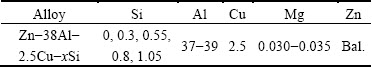
One ternary Zn-38Al-2.5Cu and four quaternary Zn-38Al-2.5Cu-xSi (x=0.3, 0.55, 0.8 and 1.05, mass fraction, %) alloys were produced using high-purity zinc (99.9%), commercially pure aluminum (99.7%), high- purity Mg(>99.97%) and Al-50%Cu, Al-12%Si master alloys. The chemical compositions of alloys are presented in Table 1. According to Table 1, the masses of Al, Cu, Mg and Si were accurately calculated and weighed. Then, the alloys were melted in a crucible using an electrical furnace and poured at a temperature of approximately (600±5) °C into a (150±5) °C preheated metallic mould. Metallographic samples were prepared using standard metallographic techniques and etched with 5% HCl + 5% HNO3 + 5% HF + 85% distilled water. The microstructures of the alloys were measured from observations under scanning electron microscope (SEM). To identify the phase components occurring in the alloy, energy dispersive spectroscopy (EDS) was performed.
The hardness was measured by Brinell hardness tester. Tensile strength and elongation were determined using the testing machine at a cross-head speed of 1 mm/min. The hardness and tensile test results were determined by taking the average of five readings.
Table 1 Chemical compositions of alloys (mass fraction, %)
2.2 Fatigue tests
All the fatigue tests were performed using a self-restraint thermal fatigue testing machine developed by Jilin University, as shown in Fig. 1. The specimens were thermally cycled in the resistance furnace at 225 °C for 120 s, followed by cooling in flowing water at room temperature for 10 s, thus one cycle was finished.
A detailed profile of the thermal fatigue specimen was shown in Fig. 2. The specimen had a 3 mm deep V-notch on the side. The purpose was to give a reasonable low initiation life and a situation where the crack initiated naturally. The fatigue crack length (optical microscopy observations) was conducted after preconcerted cycles, whilst the samples were weighed before and after the cycles by an electronic balance with an accuracy of ±0.1 mg to determine the mass change (including the spalled oxide). Scanning electron microscope investigations were performed to observe the morphology and propagation of cracks. In addition, the fractography analysis (SEM observations of failed specimens) was conducted in order to understand the fatigue damage mechanisms.
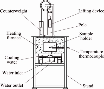
Fig. 1 Schematic diagram of self-restraint thermal fatigue tester
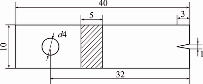
Fig. 2 Fatigue specimen geometry (unit: mm)
3 Results and discussion
3.1 Microstructure
The typical microstructures of Zn-38Al-2.5Cu with different additions of Si (0, 0.3%, 0.55%, 0.8% and 1.05%) are shown in the SEM images presented in Figs. 3(a)-(e), which are named as Samples 1, 2, 3, 4, and 5, respectively. The microstructures of the alloys consist of α(Al-rich) dendrites, eutectoid α+η (η is Zn-rich) resulted from α-phase decomposition at 275 °C, ε(CuZn4) and Si phases. The higher magnification of ZA38-1.05%Si is shown in Fig. 3(f). Both the α dendrites (Al-based solid solution) and eutectoid α+η show lamellar distribution.
The addition of Si has effects on both the dendritic morphology and phase composition of the alloys. As the Si addition increases from 0 to 0.55%, the size of α dendrites decreases gradually, whilst the amount of Si phases increases and show more homogeneous distribution, as shown in Figs. 3(a), (b) and (c). It is known that α dendrites are produced firstly during solidification, then the Si phases are precipitated, forming the constitutional supercooling at the boundaries. As a result, the development of α dendrites is restricted [11].
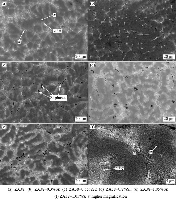
Fig. 3 SEM images of composites
However, when the Si addition of the alloys exceeds 0.55%, the coarsing α dendrites develop and the Si phases become larger and aggregate along the dendrites boundaries, as seen in Figs. 3(d) and (e). It is related to the decrease of constitutional supercooling [11]. Also, the Si phases gather together as the form of needles and polygons, forming the stress concentration, which diminishes the pinning effect on the boundaries. Thus, the developing rate of α dendrites increases. It can be concluded that the addition of 0.55% Si has a noticeable benefit in terms of the refinement of Zn-38Al-2.5Cu alloys.
3.2 Mechanical properties
The mechanical properties, including tensile strength, hardness and elongation of the alloys with different Si additions, are shown in Fig. 4. It can be seen that the hardness increases gradually. But the elongation of these alloys decreases with the increase of Si. However, the tensile strength of the alloys increases with increasing Si addition up to 0.55%, above which it decreases as the Si addition increases.

Fig. 4 Influence of Si addition on tensile strength, Brinell hardness and percentage elongation of Zn-38Al-2.5Cu alloys
These results may be explained in terms of microstructural features and constituents of the alloys. When the Si addition increases from 0 to 0.55%, the α dendrites become smaller, which contribute to the increase of both hardness and tensile strength. Also, the fine Si phases well distributed in the alloys act as obstacles to the movement of dislocations during the deformation process. When the Si addition exceeds 0.55%, the hard Si phases are the dominant factors of the continuously increasing hardness, while the tensile strength decreases related to both growing α dendrites and the stress concentration caused by the needlelike and polygonal morphologies of the Si phases [9,12]. The formation of hard and brittle Si phases weakens the interdendritic regions of the alloys and forms stress concentration, resulting in the decrease of the percentage elongation of the alloys [13,14].
3.3 Thermal fatigue behavior
3.3.1 Fatigue crack growth curves
The relationship between crack length (a) and number of cycles (N) of the alloys with different Si additions is represented in Fig. 5. Crack length is determined from the optical microscope image. Totally, there are two stages of the fatigue crack growth: crack initiation and crack propagation. As can be seen, the alloys show long incubation time of the cracks under the thermal fatigue, and then cracks propagate at a relatively high speed, afterwards, the cracks propagation shows the slow-growth stage. It is worth noting that the cracks of Samples 1 and 5 show the trend to propagate at higher speed compared to other alloys finally. For comparison, Sample 3 shows the longest incubation time and smallest rate of propagation, followed by Samples 2, 4, 1, 5. Namely, the alloy with 0.55% Si shows the highest fatigue strength, which is mainly attributed to the refined microstructure and excellent mechanical properties.
As is well-known, compressive stress is produced in the heating process, while tensile stress is produced in the cooling during the thermal fatigue, thus relevant deformation will be generated in V-notches [15]. Fatigue crack initiation and propagation will be dominated by the deformation accumulation. Grain boundaries act as barriers in deformation accumulation, besides, Si phases with uniform distribution provide weaker stress concentration [16]. So, it is hard for the crack of Sample 3 with fine microstructure to initiate and propagate.
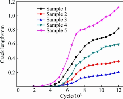
Fig. 5 Thermal fatigue crack growth data of ZA38 alloys with different Si additions
3.3.2 Crack growth behavior
The typical example of fatigue crack growth in V-notch is shown in Fig. 6. The oxides and pits are easy to be found in V-notch (see Fig. 6(a)). Usually, pit, the reflection of plastic deformation because of the thermal stress, is the origin of the crack, while the oxides provide routes for crack developing. Microscopic analysis shows that the process of thermal fatigue crack initiation includes three stages: the formation of oxide film, pits generated within the oxide film, and the growth of the pits or the formation of crack from pits.
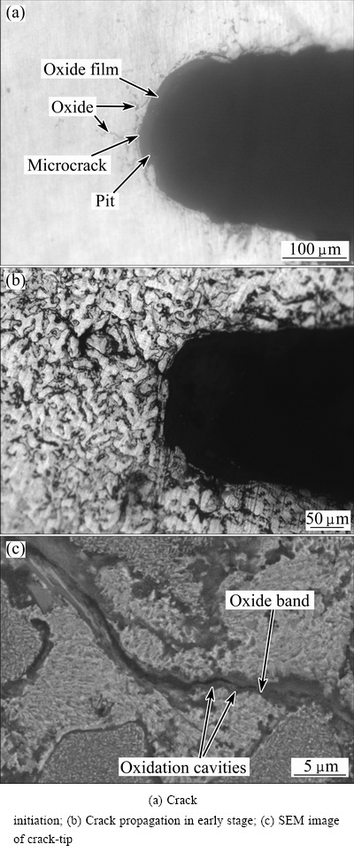
Fig. 6 Crack growth morphology of thermal fatigue
Most of the fatigue cracks grow along the dendrites boundaries, because the oxides are mainly produced in the eutectic region (see Fig. 6(b)). Furthermore, oxide band is formed in the crack region (see Fig. 6(c)). Stress assisted grain boundary oxidation (SAGBO) might account for the crack growth with temperature [17]. During the thermal fatigue test, the kinetics of oxygen diffusion and oxidation will be increased in the vicinity of the V-notch at high temperatures. Chemical bonds between atoms of the alloy are easily broken and the cohesion of the grain boundary decreases due to the oxidation. The oxide morphology and EDS of thermal fatigue fracture surface are shown in Fig. 7. As can be seen, the oxide is porous and loose. In addition, the thermal expansion coefficients of the alloy and oxide are different, thus, the oxide may shed from the specimen, forming oxidation cavities (see Fig. 6(c)), which in turn promotes the oxidation behavior. Also, the EDS analysis shows that the oxide is rich in O, Zn and Al, leading to the decrease of Zn and Al of the alloys, which decreases the strength of ZA38 alloys.
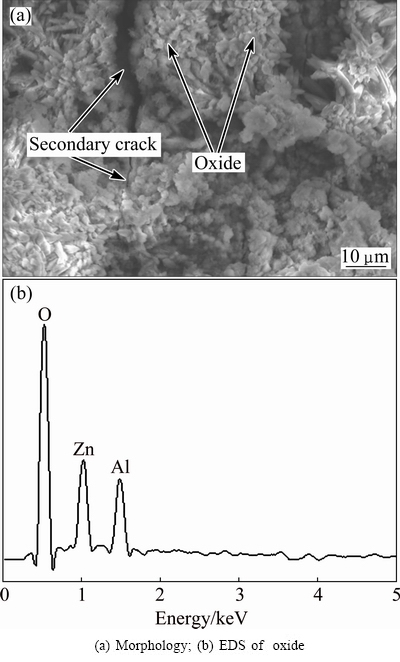
Fig. 7 Oxide of fracture surface
The mass change of the alloys during the thermal fatigue is shown in Fig. 8. The oxidation kinetics curves show the continuous mass growth trend. The positions with open symbols show the moments when spalled oxides occur, which mainly happens during the crack propagation. After the shedding of the oxide, there is a rapid increase of the mass change, resulting from the formation of oxidation cavities. The oxidation area is increased because of the cavities, leading to further oxidation. Coupled with the effect of thermal stress, the oxidation becomes more serious. As can be seen, the mass changes after 12000 cycles in decreasing order are Samples 5, 1, 4, 2, 3, respectively, which are in accordance with the fatigue crack growth curves (see Fig. 5).
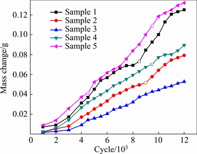
Fig. 8 Oxidation kinetic curves of ZA38 alloys
3.3.3 Crack fracture
The typical symbol of the fracture surface is shown in Fig. 9(a), which reveals the fatigue striations. SEM images of the fatigue fracture surfaces of the ZA38 and ZA38-1.05%Si alloys at 61500 cycles are shown in Figs. 9(b) and (c), when other alloys have not shown the trend to fracture. That may be related to the slow-growth stage of Samples 1 and 5, which show higher cracking speed compared to other alloys (see Fig. 5). It is clear that the failure modes of fatigue are the mixture of intergranular and transgranular modes with secondary cracks, regardless of the difference in Si addition. The formation of the secondary cracks is due to the fatigue crack propagation from the fracture surface to the inside of the alloys. The proportion of intergranular crack of the alloy with 1.05% Si is higher than the one without Si and the secondary crack becomes coarser and longer. Moreover, the brittle Si phases of ZA38-1.05%Si alloy fracture, which may result in the formation of voids.
3.4 Thermal fatigue mechanism
Actually, there is little essential difference between crack initiation and propagation, both of them are the damage processes caused by local plastic strain accumulation. Plastic passivation model presented by LAIRD can show the process of crack growth [18]. In general, it is a process of crack opening, passivation, extension and sharpening constantly. As can be seen from Fig. 5, the process of crack propagation can be divided into two stages: the fast-growth stage after crack incubation time and the following slow-growth stage.
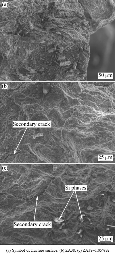
Fig. 9 SEM images of fracture surface
Crack growth rate, da/dN, is the slope of the fatigue crack growth curve shown in Fig. 5. In the fast-growth stage of crack propagation, cracks grow at a relatively high speed, which can be explained by Paris law [19]:
 (1)
(1)
where C and m are basic parameters designed by the experiment, f is the geometric correction factor, σ is thermal stress and a is the crack length. Under certain Δσ, da/dN increases with increasing crack length. Besides, the oxide band in front of the crack provides the minimum energy for crack to propagate. So, the thermal fatigue cracks of the alloys propagate at a high speed.
It can also be seen from Fig. 5 that cracks propagation of the alloys shows slow-growth stage after a certain number of cycles, which mainly results from the formation of secondary cracks. The secondary cracks perpendicular to crack propagation direction can be observed clearly on fracture surfaces (see Fig. 9). Secondary cracks can reduce the stress concentration of the main crack tip, delaying the propagation of cracks. Besides, during the thermal fatigue test, plastic deformation region will be formed in front of the crack. When the crack passes through the region, residual plastic deformation may be produced at the end of the crack tip, resulting in smaller opening displacement compared to cracks without residual plastic deformation. Thereby, crack may close during the cooling process, and may not open immediately when heating [20]. On the other hand, thermal stress is produced around the cracks during the thermal fatigue test, and it is released by crack propagation, thus the crack propagation rate reduces [21]. All of these result in the slow-growth stage of the crack propagation.
When the cracks propagate after the fast-growth stage, the alloys with 0.3%, 0.55% and 0.8% Si have shown the relatively steady states, while the cracks of ZA38 and ZA38-1.05%Si keep growing (see Fig. 5). The crack-tips SEM images of the alloys with 0.3%, 0.55% and 0.8% Si at 11500 cycles are shown in Fig. 10.
As shown in Fig. 10, the crack of ZA38-0.55%Si alloy is relatively straight and thin, while the cracks of 0.3% Si and 0.8% Si show higher tortuosity. It illustrates that ZA38-0.3%Si and ZA38-0.8%Si show poor plasticity and distribution in microstructure, which is in accordance with Fig. 3. And both of them show sharper tips of the cracks, indicating the trend of crack closure. The crack-tip of ZA38-0.55%Si is in passivation, which suffers great resistance because of the existence of the Si phase (see Fig. 10(b)). Generally, crack propagates along α dendrites supported by the principle of the minimum energy dissipation. And the strength in vicinity of the crack-tip decreases, resulting from the accumulation of plastic deformation. Furthermore, oxides in eutectic region have a significant effect on crack propagation. Thus, it is easy for the crack to propagate intergranularly. The crack can also propagate intergranularly and transgranularly in union (see Fig. 10(c)). In detail, the crack of ZA38-0.8%Si propagates intergranularly before reaching α dendrite, then continues to propagate along α dendrite, finally, the crack grows transgranularly, resulting from the oxidation.
In total, the fatigue properties of the alloys are dominated by a number of factors including the microstructural features of the alloys (grain sizes, grain boundary structures and additional phases formed during solidification), mechanical properties and the oxidation.

Fig. 10 Morphologies of crack-tips
4 Conclusions
1) The addition of Si to ZA38 alloys can refine the α dendrites in the microstructure and increase the mechanical properties because of the constitutional supercooling. ZA38-0.55%Si alloy shows the best comprehensive performance. When Si addition exceeds 0.55%, α dendrites develop and Si phases become larger.
2) Attributed to the refined microstructure and excellent mechanical properties, ZA38-0.55%Si alloy shows the longest incubation time and smallest rate of propagation, indicating the best thermal fatigue properties.
3) Oxidation plays an important role in the process of thermal fatigue crack growth. The strength of ZA38 alloys is decreased because of the oxide which is rich in O Zn and Al, and oxidation cavities are formed because of the shedding of the porous and loose oxide, which makes the cracks easy to develop along the dendrites boundaries.
4) The thermal fatigue cracks propagate and fracture by the mixture of intergranular and transgranular modes. The crack growth obeys Paris law during the fast-growth stage of the crack propagation. While the formation of secondary cracks reduces the stress concentration of the main crack tip, resulting in the slow-growth stage.
References
[1] LI Run-xia, LI Rong-de, BAI Yan-hua, QU Ying-dong, YUAN Xiao-guang. Effect of specific pressure on microstructure and mechanical properties of squeeze casting ZA27 alloy [J]. Transactions of Nonferrous Metals Society of China, 2010, 20(1): 59-63.
[2] ABOU EL-KHAIR M T, LOTFY A, DAOUD A, EL-SHEIKH A M. Microstructure, thermal behavior and mechanical properties of squeeze cast SiC, ZrO2 or C reinforced ZA27 composites [J]. Materials Science and Engineering A, 2011, 528: 2353-2362.
[3] SAVASKAN T, HEKIMOGLU A P, PURCEK G. Effect of copper content on the mechanical and sliding wear properties of monotectoid-based zinc-aluminum-copper alloys [J]. Tribology International, 2004, 37: 45-50.
[4] XU Liang, SI Nai-chao, LIU Guang-lei, XU Chao, YIN Fu-xiao, WAN Hao. Effect of manganese on microstructures and thermal fatigue properties of Zn-38Al-2.2Cu casting alloy [J]. Nonferrous Metals: Extractive Metallurgy, 2013, 11: 55-60. (in Chinese)
[5] BABIC M, MITROVIC S, JEREMIC B. The influence of heat treatment on the sliding wear behavior of a ZA-27 alloy [J]. Tribology International, 2010, 43: 16-21.
[6] LU Yun-hai, ZHAO Pin, SHEN Huan-xiang. Effect of Mn and Ni alloying on microstructures and mechanical properties of ZA27 alloy [J]. The Chinese Journal of Nonferrous Metals, 2005, 15(12): 1960-1967. (in Chinese)
[7] TAN Yin-yuan, YAN Han-fang. Effect of RE on constituent phases of ZA27 alloy [J]. The Chinese Journal of Nonferrous Metals, 2001, 11(1): 72-74. (in Chinese)
[8] CHEN Fei, WANG Tong-min, CHEN Zong-ning, MAO Feng, HAN Qiang, CAO Zhi-qiang. Microstructure, mechanical properties and wear behaviour of Zn-Al-Cu-TiB2 in situ composites [J]. Transactions of Nonferrous Metals Society of China, 2015, 25(1): 103-111.
[9] VENCL A, BOBIC I, VUCETIC F, BOBIC B, RUZIC J. Structural, mechanical and tribological characterization of Zn25Al alloys with Si and Sr addition [J]. Materials and Design, 2014, 64: 381-392.
[10] DEZECOT S, BROCHU M. Microstructural characterization and high cycle fatigue behavior of investment cast A357 aluminum alloy [J]. International Journal of Fatigue, 2015, 77: 154-159.
[11] YU Jin-wen, ZHANG Ping-ze, TENG Xin-ying. Effect of Ce on microstructures of Al-12Si Alloy [J]. Metallic Functional Materials, 2011, 18(1): 39-43. (in Chinese)
[12] LIU Guang-lei, SI Nai-chao, SUN Shao-chun, WU Qin-fang. Effects of grain refining and modification on mechanical properties and microstructures of Al-7.5Si-4Cu cast alloy [J]. Transactions of Nonferrous Metals Society of China, 2014, 24(3): 946-953.
[13] ZHOU Hong-wei, LI Yuan-dong, MA Ying, ZHANG Xin-long, LIU Xing-hai. Microstructure and solidification behavior of Al-18%Si hypereutectic alloy prepared by controlled diffusion solidification [J]. The Chinese Journal of Nonferrous Metals, 2014, 24(7): 1761-1770. (in Chinese)
[14] SAVASKAN T, AYDINER A. Effects of silicon content on the mechanical and tribological properties of monotectoid-based zinc- aluminum-silicon alloys [J]. Wear, 2004, 257: 377-388.
[15] WUNDERLICH W, HAYASHI M. Thermal cyclic fatigue analysis of three aluminum piston alloys [J]. International Journal of Material and Mechanical Engineering, 2012, 1: 57-60.
[16] CHEN Lu, YAN An, LIU Hua-shan, LI Xiao-qian. Strength and fatigue fracture behavior of Al-Zn-Mg-Cu-Zr(-Sn) alloys [J]. Transactions of Nonferrous Metals Society of China, 2013, 23: 2817-2825.
[17] LIU Xing-bo, KANG B, CHANG K M. The effect of hold-time on fatigue growth behaviors of WASPALOY alloy at elevated temperature [J]. Materials Science and Engineering A, 2003, 340: 8-14.
[18] TORIBIO J, KHARIN V. Simulations of fatigue crack growth by blunting-re-sharpening: Plasticity induced crack closure vs. alternative controlling variables [J]. International Journal of Fatigue, 2013, 50: 72-82.
[19] WANG Huan, YUAN Chao, GUO Jian-ting, QIN He-yong. Fatigue crack growth behavior of GH4698 alloy [J]. The Chinese Journal of Nonferrous Metals, 2015, 25(1): 23-29. (in Chinese)
[20] FISCHER C, SCHWEIZER C, SEIFERT T. Assessment of fatigue crack closure under in-phase and out-of-phase thermomechanical fatigue loading using a temperature dependent strip yield model [J]. International Journal of Fatigue, 2015, 78: 22-30.
[21] XIA Peng-cheng, YU Jin-jiang, SUN Xiao-feng, GUAN Heng-rong, HU Zhuang-qi. Thermal fatigue properties of DZ40M alloy [J]. Rare Metal Materials and Engineering, 2011, 40(1): 152-155.
刘 婷,司乃潮,刘光磊,张 瑞,祁昌洋
江苏大学 材料科学与工程学院,镇江 212013
摘 要:研究了添加Si对Zn-38Al-2.5Cu合金显微组织、力学性能及热疲劳性能的影响。结果表明:Si的添加使锌铝合金产生成分过冷。当Si添加量为0.55%时,合金组织细化显著,力学性能最优。继续添加Si,Si相聚集长大,晶粒粗化,合金力学性能下降。由于塑性变形形成的凹坑及氧化是热疲劳裂纹萌生的主要原因。在裂纹扩展前期,裂纹附近形成的疏松多孔的氧化区加快裂纹生长,符合Paris公式,裂纹主要沿晶界扩展。裂纹扩展后期,二次裂纹的快速生长吸收了主裂纹生长所需的部分能量,裂纹进入缓慢增长阶段,裂纹变为沿晶和穿晶混合的扩展特征。
关键词:Zn-38Al-2.5Cu合金;Si添加;力学性能;热疲劳;裂纹生长;氧化
(Edited by Yun-bin HE)
Foundation item: Project (BC2012211) supported by the Science and Technology Enterprises Innovation Fund of Jiangsu Province, China
Corresponding author: Nai-chao SI; Tel: +86-13775365246; E-mail: snc@ujs.edu.cn
DOI: 10.1016/S1003-6326(16)64290-5

