Corrosion fatigue crack growth mechanisms in welded joints of marine steel structures
来源期刊:中南大学学报(英文版)2021年第1期
论文作者:邵飞 白林越 徐倩 马青娜 申玫
文章页码:58 - 71
Key words:welded joints; corrosion fatigue; growth mechanism; multi-factor
Abstract: This paper presents a model of fatigue crack growth in a welded joint and a two-dimensional model of anodic dissolution based on Donahue model and anodic dissolution mechanism, respectively. In addition, a model for predicting the corrosion fatigue crack growth rate in welded joints of steel marine structures is established and crack growth mechanisms are analyzed. The results show that during early stages of crack growth, corrosion fatigue crack growth rate in welded joints is mainly controlled by corrosion action, whereas cyclic loading becomes more influential during the later stage of crack propagation. Loading frequency and effective stress ratio can affect rupture period of protective film at the corrosion fatigue crack tip and the length of corrosion crack increment, respectively, which changes the influence of corrosion action on crack growth rate. However, the impact of stress amplitude on crack growth rate is only significant when crack propagation is caused by cyclic loading. Welding residual stress not only improves the effective stress ratio of cyclic loading, but also promotes crack closure and increases corrosion fatigue crack growth rate in welded joints. Compared to corrosion action, welding residual stress has a more significant influence on crack growth caused by cyclic loading.

J. Cent. South Univ. (2021) 28: 58-71
DOI: https://doi.org/10.1007/s11771-021-4586-0

XU Qian(徐倩), SHAO Fei(邵飞), BAI Lin-yue(白林越), MA Qing-na(马青娜), SHEN Mei(申玫)
College of Field Engineering, Army Engineering University of PLA, Nanjing 210007, China
 CentralSouthUniversityPressandSpringer-VerlagGmbHGermany,partofSpringerNature 2021
Abstract: This paper presents a model of fatigue crack growth in a welded joint and a two-dimensional model of anodic dissolution based on Donahue model and anodic dissolution mechanism, respectively. In addition, a model for predicting the corrosion fatigue crack growth rate in welded joints of steel marine structures is established and crack growth mechanisms are analyzed. The results show that during early stages of crack growth, corrosion fatigue crack growth rate in welded joints is mainly controlled by corrosion action, whereas cyclic loading becomes more influential during the later stage of crack propagation. Loading frequency and effective stress ratio can affect rupture period of protective film at the corrosion fatigue crack tip and the length of corrosion crack increment, respectively, which changes the influence of corrosion action on crack growth rate. However, the impact of stress amplitude on crack growth rate is only significant when crack propagation is caused by cyclic loading. Welding residual stress not only improves the effective stress ratio of cyclic loading, but also promotes crack closure and increases corrosion fatigue crack growth rate in welded joints. Compared to corrosion action, welding residual stress has a more significant influence on crack growth caused by cyclic loading.
Key words: welded joints; corrosion fatigue; growth mechanism; multi-factor
Citethisarticleas: XU Qian, SHAO Fei, BAI Lin-yue, MA Qing-na, SHEN Mei. Corrosion fatigue crack growth mechanisms in welded joints of marine steel structures [J]. Journal of Central South University, 2021, 28(1): 58-71. DOI: https://doi.org/10.1007/s11771-021-4586-0.
1 Introduction
Welding is widely used to connect steel components of marine structures. However, welded joints have complex microstructures that retain high levels of welding residual stress, and therefore, often promote initiation of corrosion fatigue cracks. Moreover, the combined effects of the marine environment and wave loading can quickly lead to corrosion fatigue failure of welded marine structures [1-3]. Thus, the corrosion fatigue life of welded joints is much shorter in marine environments compared to inert environments; moreover, the safety and integrity of welded marine structures are often reduced by corrosion. Therefore, further investigation on corrosion fatigue crack growth mechanisms in welded joints of marine steel structures is merited to improve both the safety and service life of steel marine structures.
Compared to the fatigue process in inert environments, corrosion fatigue of welded joints in marine environments is more complex; nonetheless, some important results have been achieved to date. ZHAO et al [4] used finite element simulations to study the corrosion fatigue crack initiation mechanism of X80 steel in a marine environment and showed that, in addition to the effects of corrosion pit-induced stress concentrations, corrosion products that adhere to the metal surface can promote the initiation of corrosion fatigue cracks. In another study, CHANG [5] used acoustic emissions to examine the corrosion fatigue crack growth mechanism of X52 steel and AZ31 aluminum alloy in a 3.5% sodium chloride (NaCl) solution, and found that for X52 steel, anodic dissolution is the main mechanism of corrosion fatigue crack propagation in simulated seawater. Meanwhile, WU et al [6] reported that corrosion fatigue crack growth is accelerated in the marine environment when the surrounding temperature increases, and the impact of temperature on the corrosion fatigue crack growth rate of FV520B steel was most significant at relatively low stress amplitudes.
At present, most research on corrosion fatigue is empirically performed in a simulated marine environment. However, materials used in welded joints, and therefore corrosion fatigue crack growth mechanisms, vary widely in real-world conditions and real-world parameters differ greatly from the corrosion and loading parameters used in experiments; therefore, previous empirical results cannot be universally adopted. Moreover, real- world data on corrosion fatigue crack growth mechanisms of welded joints in steel marine structures are difficult and expensive to obtain due to harsh marine environments. Theoretical studies can considerably shorten research time, reduce research costs, and produce results with universal applicability. To this end, theoretical research on corrosion fatigue crack growth mechanisms of welded joints in steel marine structures can effectively fill the gaps in existing experimental research.
The initiation region and growth rate of a corrosion fatigue crack are determined by many factors including the weld geometry, microstructures of different zones of the welded joint, stress concentrations, weld defects, and the crack growth path [7-9]. As a result, theoretical parameters must be treated as random variables affected by a number of influencing factors, which increases the complexity of theoretical analyses. Owing to the geometry, microstructure, and stress concentration at the weld toe, this area is typically the most sensitive to corrosion fatigue crack initiation in defect-free joints [10-12]. Therefore, studies on corrosion fatigue crack initiation at the weld toe are greatly important and the research can be universally applied.
This paper presents a model for predicting fatigue crack growth rate based on the model proposed by DONAHUE et al [13]. By introducing additional parameters including the shape coefficient, opening ratio, and welding residual stress, the Donahue crack growth model can be extended to welded joints. Meanwhile, a two-dimensional model of corrosion-induced anodic dissolution is established according to the anodic dissolution mechanism. Then, fatigue crack growth model and the anode dissolution rate model are combined to establish a new model suitable for calculating the corrosion fatigue crack growth rate of welded joints in steel marine structures. The proposed model was validated and can be used to effectively analyze corrosion fatigue crack growth mechanisms in welded joints of steel marine structures. The influences of various factors on the corrosion fatigue crack growth rate are discussed.
2 Fatigue crack growth model of welded joint
2.1 Model selection
2.1.1 Basic fatigue crack growth model
In 1963, PARIS et al [14] proposed a formula for calculating the fatigue crack growth rate. Further to this, FORMAN [15] and DONAHUE et al [13] proposed several fatigue crack growth models with a wider range of applications. However, as the scope of application increased, more experimental parameters were required to perform calculations, which placed practical limitations on the model.
To reduce the number of unknown parameters and consider many stages of fatigue failure of welded joints as possible, the basic form of the fatigue crack growth model proposed by DONAHUE et al [13] can be expressed as
 (1)
(1)
where  is the fatigue crack growth rate in an inert environment; △K is the stress intensity factor (SIF) range; △Kth is the threshold of the SIF range; and C and m are material constants. When predicting the corrosion fatigue crack growth rate, the model proposed by DONAHUE et al [13] can eliminate the influence of the crack initiation stage on the prediction of the crack growth rate during the stable growth stage, and is therefore suitable for the aims of our study.
2.1.2 Stress intensity factor range
High temperature and uneven heating can produce irregular deformation of a joint during the welding process, resulting in a different stress distribution on the welded surface compared to the unwelded metal. Therefore, the traditional formula for calculating the SIF of a surface crack of a welded joint must be improved. Most experimental results suggest that a load parallel to the crack growth direction will have little effect on crack propagation. Therefore, in the mathematical model, the load acts perpendicular to the direction of crack growth and is modeled as unidirectional stress.
The SIF range of the surface crack of the welded joint can be expressed as [16]
 (2)
(2)
where  is a complete elliptic integral of the second kind; Ms is the free surface correction coefficient; MT is the finite thickness correction factor; Mk is the correction factor of the weld toe; △σ is the actual stress amplitude; and a is the crack depth.
Furthermore, if the following two conditions are met: 1) There is no longitudinal fillet weld on the surface of the welded joint; 2) The welded joint does not bear the load directly. then, the average contour of the weld can be expressed as [16, 17]
 (3)
(3)
where c is the semi-elliptical surface crack length.
Correction factor MsMT/Φ0 can be used to modify the SIF of a surface crack in the welded joint [16]:

 (4)
(4)
where B is the thickness of the welded plate.
The value of Mk can be calculated as [17]
 (5)
(5)
 (6)
(6)
where θ is a degree related to the residual height of the welded joint, as shown in Figure 1.

Figure 1 Physical meaning of θ
2.1.3 Threshold value of SIF range
The threshold value of the SIF range (△Kth) is closely related to the metal type, service environment, and stress ratio. Hence, △Kth used in calculations is generally obtained experimentally, which increases the number of experiments required. To solve this problem, YU [18] proposed the concept of fatigue crack growth threshold value. The empirical formula for fatigue crack growth threshold can be obtained by summing experimental values, as follows:
 (7)
(7)
where ath is the fatigue crack growth threshold value and b1 is the fatigue strength factor, expressed as
 (8)
(8)
When a≥ath, the fatigue crack is considered to be in the stable growth stage.
2.1.4 Opening ratio
Fatigue cracks in welded joints are only considered fully open when the cyclic tensile load exceeds a certain critical value, referred to as the crack closure effect. The closure effect has a significant influence on the crack growth threshold value and results in significant changes of residual fatigue lifetime of welded joints [19]. Owing to the complexity of experimental methods for calculating the opening ratio, researchers are constantly searching for a theoretical method. Many literatures consider the closure effect by introducing the opening ratio into computational model, and the calculation models with higher accuracy are achieved, such as the iLAPS model [20] and modified NASGRO equation [21]. The formula used for calculating the opening ratio can be expressed as [22]:
 (9)
(9)
where
 (10)
(10)
 (11)
(11)
 (12)
(12)
 (13)
(13)
 (14)
(14)
where α is the stress-strain constraint coefficient, which is equal to 1 during the plane stress state and equal to 3 under the plane strain state; σf is the flow stress. Flow stress σf can be expressed as [23]
 (15)
(15)
where σy is the yield strength and σu is the tensile strength.
The opening ratio can be solved by substituting Eqs. (10)-(15) into Eq. (9).
2.1.5 Welding residual stress
The SIF due to welding residual stress can be calculated using the weight function method. If the welding residual stress distribution perpendicular to the direction of crack growth is σres(x), the SIF increment due to welding residual stress can be expressed as
 (16)
(16)
where x is the distance from the crack initiation point along the crack growth direction and h(x, a) is the weight function.
To facilitate this calculation, the relationship between the welding residual stress and the position of the crack can be simplified using a piecewise function, as shown in Figure 2 [24].
If a≤b,
 (17)
(17)
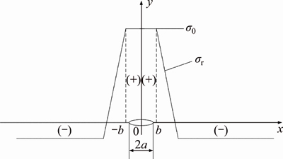
Figure 2 Simplified representation of welding residual stress distribution ((+) denotes tensile stress section and (-) denotes compressive stress section)
where is the welding residual stress at the crack tip perpendicular to the crack growth direction. The positive and negative values of represent the residual tensile stress and the residual compressive stress, respectively.
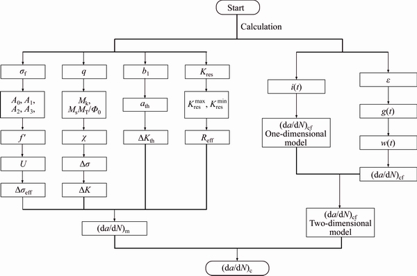
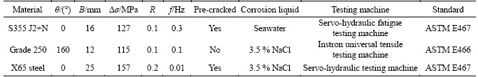
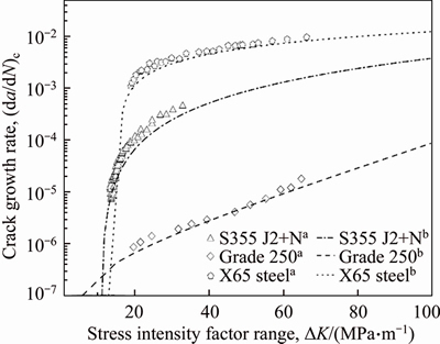
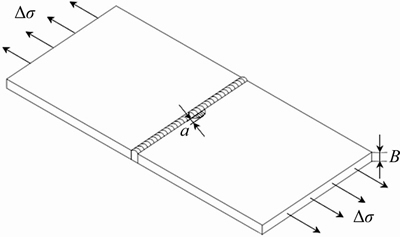
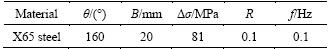
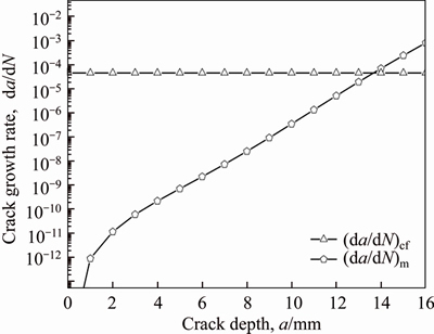
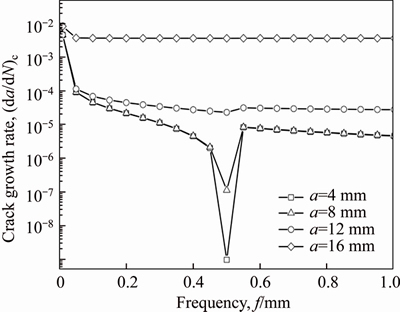
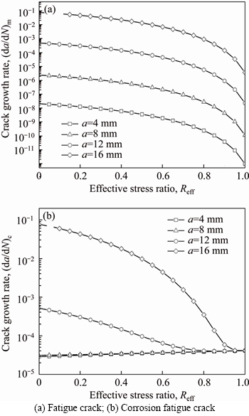
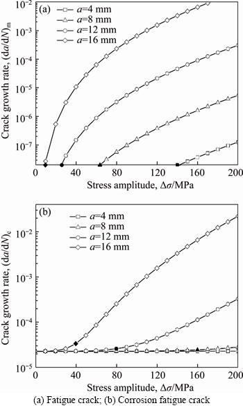
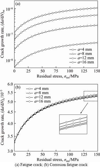
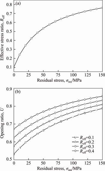
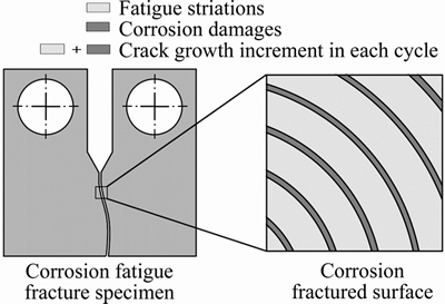
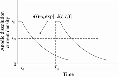
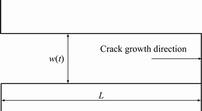
If b 2.2 Model deduction Based on the equations in Section 2.1, the fatigue crack growth model of welded joint can be deduced. Substituting the shape coefficient Since Then, substituting Eq. (20) into Eq. (19), we obtain where σmax is the maximum cyclic stress and R is the actual stress ratio. By substituting Eqs. (4)-(6) and χ(a, B, θ) into Eq. (21), the SIF range of the surface crack of the welded joint can be solved. Meanwhile, by substituting Eqs. (7) and (8) into Eq. (21), the threshold value of the SIF range for a surface crack of the welded joint can be also achieved: The crack closure effect can be included by introducing the opening ratio into the fatigue crack growth model. Therefore, the relationship between the effective stress amplitude and the actual stress amplitude is where △σeff is the effective stress amplitude, and U is the opening ratio. The SIF at a crack tip containing welding residual stress can be obtained by superimposing the SIF of the crack tip without the welding residual stress field and the SIF with the welding residual stress field according to ASME-FFS/API 579-1. Therefore, when welding residual stress is present, the effective SIF of the crack tip is where The presence of welding residual stress will not affect the SIF range of crack tip but will change the fatigue crack growth rate by influencing the effective stress ratio of cyclic loading. Considering welding residual stress, the effective stress ratio of cyclic loading is where Reff is the effective stress ratio. Substituting Eqs. (16)-(18) and (24) into Eq. (25), the effective stress ratio of cyclic loading considering welding residual stress can be obtained and the influence of welding residual stress can be introduced into the model. By determining the shape coefficient, SIF range, threshold value of the SIF range, opening ratio, and welding residual stress of the welded joint, the fatigue crack growth rate of welded joint can be calculated by substituting Eqs. (21)-(23) into Eq. (1). Replacing △σ and R with △σeff and Reff, respectively, the model can be expressed as 3 Model of corrosion fatigue crack growth in welded joint 3.1 Basic corrosion fatigue crack growth model The corrosion fatigue failure of welded joints caused by the corrosion and cyclic loading is complicated. Under the influence of corrosion, the corrosion damage and crack source regions will first appear between the area of weld joint and heat-affected zone [25]. During the growth of corrosion fatigue crack, the passivation film at the crack tip will be teared under the action of cyclic loading, and then the corrosion of bare metal at the crack tip is promoted and the growth of crack is further accelerated. The corrosion process of bare metal at the crack tip is shown in Figure 3. Both the corrosion and fatigue damages can be observed at the fracture of corrosion fatigue crack, and the fatigue striations and corrosion damages will appear alternately on the surface of the fracture as shown in Figure 4 [26-28]. Figure 3 Corrosion process of bare metal at crack tip Figure 4 Corrosion and fatigue damages at fracture of corrosion fatigue crack The corrosion and fatigue behaviors of welded joints can be analyzed separately in corrosion fatigue life prediction [29, 30]. According to the corrosion environment and material, the basic model for calculating corrosion fatigue crack growth rate can be divided into three separate models: superposition model, competition model, and dislocation dipole model. High-strength steel is often used in marine structures; therefore, the superposition model is chosen as the base model for calculating the corrosion fatigue crack growth rate of the welded joint [31]: where where f is the loading frequency. 3.2 One-dimensional model of anodic dissolution When a welded structure is subjected to fatigue loading in a corrosive environment, stress concentration phenomena occur at the crack tip and accelerate the oxidation reaction of the bare metal surface. Metal atoms lose electrons, which are converted into metal ions that diffuse into the corrosive medium, leading to anodic dissolution. FORD et al [32] decomposed this process into three stages: cation diffusion, fracture of the oxide film at the crack tip, and dissolution of new metal. Among them, corrosion fatigue crack growth due to anodic dissolution is mainly related to fracture of the oxide film and dissolution of new metal. According to Faraday’s law, a relationship can be established between the crack growth rate and oxidation charge density and rupture strain of the oxide film, as follows: where As bare material at the crack tip is transformed into a passivation film, current generated by the oxidation reaction is attenuated and the current density of anodic dissolution at this stage can be expressed as [33]: where i0 is the corrosion current density generated by the corrosion of new metal at the crack tip; λ is the passivation coefficient of current attenuation, and td is the generation cycle of passivated film. Changes in the anodic dissolution current density at the crack tip over time are shown in Figure 5. Figure 5 Variation of anodic dissolution current density at crack tip with time Assuming the rupture period of the oxide film at the crack tip T, the crack growth rate due to anodic dissolution can be derived from Eqs. (29) and (30) as 3.3 Two-dimensional model of anodic dissolution Since Eq. (31) presents a one-dimensional model, it cannot be superimposed with Eq. (26), which is a two-dimensional model. Therefore, it is necessary to convert Eq. (31) into a two-dimensional model. The crack growth increment due to anodic dissolution can be approximated as a rectangle and the crack width can be a time-dependent function w(t), as shown in Figure 6 [34]. The two-dimensional form of Eq. (31) is Figure 6 Crack growth increment due to anodic dissolution Under cyclic loading, the width of a parallel crack can be expressed as: where wm is the average width of crack increment under different cyclic loading periods. Function g(t) can be expressed as: where After substituting Eqs. (34) and (35) into Eq. (33), the following equation is obtained: Thus, the corrosion fatigue crack growth rate caused by anode dissolution can finally be expressed as According to the superposition principle, the corrosion fatigue crack growth rate in the welded joint can be obtained from Eqs. (26), (27) and (37), as follows: 4 Model validation A flowchart of the steps for calculating the corrosion fatigue crack growth rate of a welded joint is shown in Figure 7. To validate the model, published experimental data on the corrosion fatigue crack growth rate of welded joints of S355 J2+N, grade 250, and X65 in simulated seawater were collected [35-37], and compared with the results of the proposed model. The shape parameters of welded joints and main test parameters, taken from Refs. [35-37], are presented in Table 1. During the test, S355J2+N and X65 steel welded joints were processed into standard compact tension specimens. For calculations, parameter θ of the welded joints was taken as 0° for both the S355J2+N and X65 steel specimens. The loading mode used in the tests presented in Refs. [35-37] is stress loading. The model validation results are shown in Figure 8. From Figure 8, it can be concluded that the model proposed in this paper accurately predicts the corrosion fatigue crack growth rate of S355 J2+N, grade 250, and X65 welded joints; however, calculated results are slightly lower than published values. This is because although the superposition model adopted in the modeling process takes into account the effect of corrosion on the crack growth rate to some extent, it is difficult to fully predict the coupled effect of corrosion action and fatigue loading, which reduces the predictive ability of the model. By setting appropriate parameters in the corrosion fatigue process, the proposed model can effectively predict the corrosion fatigue crack growth rate in welded joints of different steels in the marine environment. Furthermore, the proposed theoretical approach can be used to study the corrosion fatigue crack growth mechanism of welded joints in steel marine structures. Figure 7 Analytical flow of calculation model Table 1 Shape parameters and main experimental parameters of welded joints Figure 8 Model validation (a-Published experimental results and b-Calculated values) 5 Results and discussion To study the corrosion fatigue crack growth mechanism of welded joints using the mathematical model established in this paper, we established a virtual experimental model. The virtual specimen and loading direction used in the experiment are illustrated in Figure 9. Figure 9 Virtual specimen and loading direction No pre-crack was introduced in the virtual model. Additional shape parameters are presented along with the main test parameters in Table 2. To investigate the influence of a particular parameter on the corrosion fatigue crack propagation rate of welded joints, the parameter is replaced with a free variable, which is varied throughout the analysis. Table 2 Shape parameters and main test parameters of virtual model 5.1 Influence of corrosion action and fatigue loading Both corrosion action and fatigue loading can promote corrosion fatigue failure of welded joints; however, the mechanism of action is different in each case. In this paper, the influence of corrosion action and fatigue loading on the corrosion fatigue crack growth rate in a welded joint was obtained using the proposed models for calculating fatigue crack growth rate (da/dN)m and anodic dissolution rate (da/dN)cf, as shown in Figure 10. Figure 10 Influence of corrosion action and fatigue loading on corrosion fatigue crack growth rate in a welded joint As shown in Figure 10, the effect of lifting due to corrosion on early corrosion fatigue crack growth in a welded joint is more significant than the influence of fatigue loading. This is the main reason that early growth rates of corrosion fatigue cracks are much higher than early growth rates of simple fatigue crack. During crack propagation, the influence of corrosion action on the crack growth rate remains almost unchanged, whereas the influence of fatigue loading is significantly enhanced as the crack depth increases, finally becoming the main factor controlling crack growth during later stages of crack growth. 5.2 Loading frequency Loading frequency can influence the anodic dissolution rate of metal at the crack tip by affecting the rupture period of the protective film and the amount of time base metal is exposed at the crack tip, both of which influence the corrosion fatigue crack growth rate in the welded joint. The influence of loading frequency on the corrosion fatigue crack growth rate is illustrated in Figure 11. Figure 11 Influence of loading frequency on corrosion fatigue crack growth rate During the early stages of corrosion fatigue crack propagation, the influence of loading frequency on crack growth rate is related to the generation of a passivation film. When 1/f ≥td, new metal undergoes the entire passivation film generation process during a single loading cycle. Therefore, the passivation time of the metal and the average crack width at the crack tip increase simultaneously as the loading frequency increases, which leads to a slower crack growth rate. When 1/f 5.3 Effective stress ratio The effective stress ratio affects both the fatigue crack growth rate and corrosion fatigue crack growth rate in welded joints, as shown in Figure 12. Figure 12 Influence of effective stress ratio on crack growth rate: The influence of the effective stress ratio on the fatigue crack growth rate remains the same throughout the various stages of fatigue crack growth. When the effective stress ratio increases, the slip band generated during fatigue crack growth is narrower, which reduces the fatigue crack growth rate in the welded joint (Figure 12(a)). Moreover, the crack depth does not significantly influence the impact of the effective stress ratio on the fatigue crack growth rate. On the other hand, as the effective stress ratio increases, the increment in crack width caused by anodic dissolution decreases and the increment in crack length at the crack tip increases, thereby increasing the corrosion fatigue crack growth rate. Thus, corrosion action is the main factor affecting crack growth rate during the early stages of corrosion fatigue crack propagation, and any increase in the effective stress ratio further promotes corrosion fatigue crack growth (Figure 12(b)). During the late crack growth stage, the growth rate is mainly dominated by fatigue loading and the effective stress ratio will have a similar influence on the corrosion fatigue crack growth rate and fatigue crack growth rate. 5.4 Stress amplitude The influence of stress amplitude on the fatigue crack growth rate and corrosion fatigue growth rate in the welded joint is illustrated in Figure 13. As the stress amplitude increases, the fatigue crack growth rate of the welded joint decreases, but only up to a critical value △σ0 (represented by solid black data points in Figure 13); thereafter, further increases in the stress amplitude will significantly increase the fatigue crack growth rate. Furthermore,as the crack depth increases, △σ0 will continuously decrease and only a small amount of fatigue loading will cause significant crack growth when the crack depth is very large, and increasing the stress amplitude can also speed up the fatigue crack growth rate. Figure 13 Influence of stress amplitude on crack growth rate: Since changes in stress amplitude have very little influence on corrosion action, the stress amplitude will not have significant influence on the corrosion fatigue crack growth rate during early stages of crack propagation (Figure 13(b)). Then, when the crack reaches a certain depth, the growth rate is gradually controlled by fatigue loading and the influence of stress amplitude on the corrosion fatigue crack growth rate is gradually strengthened and eventually, similar to the influence on fatigue crack growth. 5.5 Welding residual stress The influences of welding residual stress on fatigue crack growth rate and corrosion fatigue crack growth rate are illustrated in Figure 14. Figure 14 Influence of welding residual stress on crack growth rate: Welding residual stress can increase corrosion fatigue crack growth due to both corrosion action and fatigue loading. Compared to the effect of corrosion action, welding residual stress has a greater influence on fatigue loading, which enhances the dominant effect of fatigue loading on the corrosion fatigue crack growth rate. The reason that welding residual stress has a greater influence on crack growth is that an increase in welding residual stress will increase the effective stress ratio of fatigue loading (Figure 15(a)). Although the fatigue crack growth rate is reduced, welding residual stress also accelerates anodic dissolution at the crack tip, ultimately promoting corrosion fatigue crack growth. At the same time, the increase of both welding residual stress and effective stress ratio promotes corrosion fatigue crack closure (Figure 15(b)), thus accelerating fatigue crack growth in the welded joint. Although changes in welding residual stress can significantly impact the effective stress ratio under fatigue loading, the influence of welding residual stress on the opening ratio does not change significantly under different effective stress ratios. Therefore, welding residual stress can directly promote the closure effect during the fatigue crack growth process, rather than indirectly affecting the closure effect by changing the effective stress ratio. Figure 15 Influence of welding residual stress on effective stress ratio (a) and crack opening ratio (b) 6 Conclusions In this paper, a model for calculating the fatigue crack growth rate in welded joints and a two-dimensional model of anodic dissolution were presented, based on the Donahue model and anodic dissolution mechanism, respectively. In addition, the superposition principle was used to establish a model that is suitable for calculating the corrosion fatigue crack growth rate in welded joints of steel marine structures. The corrosion fatigue crack propagation mechanism in a welded joint of a steel marine structure was analyzed using the proposed model and the conclusions can be summarized as follows: 1) The corrosion fatigue crack growth model established in this paper can effectively predict the corrosion fatigue crack growth rate in welded joints made of different steels in the marine environment and offer some degree of universal applicability. The proposed theoretical model provides an effective way of studying corrosion fatigue crack growth mechanism of welded joints in steel marine structures. 2) The growth rate of corrosion cracks in welded joints during the early stages of crack propagation is mainly controlled by corrosion action. As crack depth increases, the influence of fatigue loading corrosion fatigue crack growth rate also gradually increases and becomes the dominant factor during later stages of crack growth. 3) The loading frequency can affect the rupture period of the protective film and exposure time of base material at the corrosion fatigue crack tip, which alters the contribution of corrosion action to the corrosion fatigue crack growth rate. Furthermore, the influence of fatigue loading to the corrosion fatigue crack growth rate also changes and the effective stress ratio affects the growth rate by changing the length of the corrosion crack increment. Variation of the stress amplitude only has a significant effect on the influence of fatigue loading in the corrosion fatigue crack growth process, but very little impact on the influence of corrosion action. 4) Welding residual stress can improve the effective stress ratio of cyclic loading and promote crack closure, thereby increasing the corrosion fatigue crack growth rate in welded joints. Compared to corrosion action, welding residual stress has a more significant effect on fatigue loading. Nomenclature SIF Stress intensity factor △K SIF range △Kth Threshold of SIF range Maximum effective SIF Minimum effective SIF Kres SIF increment due to welding residual stress C, m Material constants Φ0 Complete elliptic integral of the second kind Ms Free surface correction coefficient MT Finite thickness correction factor Mk Weld toe correction factor △σ Actual stress amplitude △σeff Effective stress amplitude σmax Maximum cyclic stress σf Flow stress σy Yield strength σu Tensile strength Welding residual stress at the crack tip c Semi-elliptical surface crack length a Crack depth B Welded plate thickness θ Parameter related to the residual height of the welded joint χ Shape coefficient R Stress ratio Reff Effective stress ratio ath Fatigue crack growth threshold b1 Fatigue strength factor U Opening ratio α Stress-strain constraint coefficient f Loading frequency Anodic dissolution crack growth Qf Oxidation charge density εct Strain rate at the crack tip εf Rupture strain of oxide film n Number of electrons released F Faraday’s constant M Molar mass ρ Metal density i0 Corrosion current density λ Passivation coefficient of current attenuation td Passivating time required for generating passivated film T Time of oxide film rupture at the crack tip wm Average width of crack increment Contributors SHAO Fei provided the concept and edited the draft of manuscript. XU Qian and BAI Lin-yue conducted theoretical analysis. XU Qian conducted manuscript writing, data analysis, and edited the draft of manuscript. MA Qing-na conducted a literature review survey. SHEN Mei conducted data verification and icon verification nuclear. Conflict of interest XU Qian, SHAO Fei, BAI Lin-yue, MA Qing-na and SHEN Mei declare that they have no conflict of interest. References [1] DENG L, YAN W C, NIE L. A simple corrosion fatigue design method for bridges considering the coupled corrosion-overloading effect [J]. Engineering Structures, 2019, 178: 309-317. DOI: 10.1016/j.engstruct.2018.10.028. [2] SUN J Z, DING Z H, HUANG Q. Corrosion fatigue life prediction for steel bar in concrete based on fatigue crack propagation and equivalent initial flaw size [J]. Construction and Building Materials, 2019, 195: 208-217. DOI: 10.1016/j.conbuildmat.2018.11.056. [3] WANG S Q, ZHANG D K, HU N N, ZHANG J L. Effect of stress ratio and loading frequency on the corrosion fatigue behavior of smooth steel wire in different solutions [J]. Materials, 2016, 9: 750-766. DOI: 10.3390/ma9090750. [4] ZHAO W M, WANG Y X, ZHANG T M, WANG R. Study on the mechanism of high-cycle corrosion fatigue crack initiation in X80 steel [J]. Corrosion Science, 2012, 57: 99-103. DOI: 10.1016/j.corsci.2011.12.029. [5] CHANG H. Acoustic emission study of corrosion fatigue crack propagation mechanism identification [J]. Applied Mechanics and Materials, 2014, 628: 20-23. DOI: 10.4028/www.scientific.net/AMM.628.20. [6] WU Q, CHEN X, FAN Z. Corrosion fatigue behavior of FV520B steel in water and salt-spray environments [J]. Engineering Failure Analysis, 2017, 79: 422-430. DOI: 10.1016/j.engfailanal.2017.05.012. [7] GARCIA-RENTERIA M A, LOPEZ-MORELOS V H, GONZALEZ-SANCHEZ J, GARCIA-HERNANDES R, DZIB-PEREZ L, CURIEL-LOPEZ F F. Effect of electromagnetic interaction during fusion welding of AISI 2205 duplex stainless steel on the corrosion resistance [J]. Applied Surface Science, 2016, 396: 1187-1200. DOI: 10.1016/ j.apsusc.2016.11.109. [8] BESTEN H. Fatigue damage criteria classification, modelling developments and trends for welded joints in marine structures [J]. Ships and Offshore Structures, 2018, 13: 787-808. DOI: 10.1080/17445302.2018.1463609. [9] GKATZOGIANNIS S, WEINERT J, ENGELHARDT I, KNOEDEL P, UMMENHOFER T. Correlation of laboratory and real marine corrosion for the investigation of corrosion fatigue behaviour of steel components [J]. International Journal of Fatigue, 2019, 126: 90-102. DOI: 10.1016/j.ijfatigue.2019.04.041. [10] GANDHI P, MURTHY D S R, RAGHAVA G, RAO A G M. Fatigue crack growth in stiffened steel tubular joints in seawater environment [J]. Engineering Structures, 2000, 22: 1390-1401. DOI: 10.1016/S0141-0296(99)00080-2. [11] WANG L, HUI L, ZHOU S, XU L, HE B. Effect of corrosive environment on fatigue property and crack propagation behavior of Al 2024 friction stir weld [J]. Transactions of Nonferrous Metals Society of China, 2016, 26: 2830-2837. DOI: 10.1016/S1003-6326(16)64411-4. [12] ILMAN M N, TRIWIBOWO N A, WAHYUDIANTO A, MUSLIH M R. Environmentally assisted fatigue behaviour of stress relieved metal inert gas (MIG) AA5083 welds in 3.5% NaCl solution [J]. International Journal of Fatigue, 2017, 100: 285-295. DOI: 10.1016/j.ijfatigue.2017.03.041. [13] DONAHUE T M, GUENTHER B, BLAMONT J E. Noctilucent clouds in daytime circumpolar particular layers near the summer mesopause [J]. Journal of the Atmospheric Science, 1972, 29: 1205-1209. DOI: 10.1175/1520- 0469(1972)0292.0.CO;2. [14] PARIS P C, ERDOGEN F. A critical analysis of crack propagation laws [J]. Journal of Basic Engineering, 1963, 85: 528-533. DOI: 10.1115/1.3656900. [15] FORMAN R G. Numerical analysis of crack propagation in cyclic loaded structures [J]. Journal of Basic Engineering, Transaction ASTM (Series D), 1967, 89: 459-469. DOI: 10.1115/1.3609637. [16] BOWNESS D, LEE M M K. Prediction of weld toe magnification factors for semielliptical cracks in T-butt joints [J]. International Journal of Fatigue, 2000, 22: 389-396. DOI: 10.1016/S0142-1123(00)00012-8. [17] HUANG X P, CUI W C, SHI D X. Calculation of fatigue life of surface cracks at weld toe of submarine cone-cylinder shell [J]. Journal of Ship Mechanics, 2002, 6: 62-68. DOI: 10.3969/j.issn.1007-7294.2002.04.007. (in Chinese) [18] YU Y G. Calculations and assessment for cracking strength to linear elastic materials in whole process-the genetic elements and clone technology in mechanics and engineering fields [J]. American Journal of Science and Technology, 2016, 3: 152-161. http://www.aascit.org/journal/ajst. [19] VOJTEK T, POKORNY P, KUBENA I, NAHLIK L, FAJKOS R, HUTAR P. Quantitative dependence of oxide- induced crack closure on air humidity for railway axle steel [J]. International Journal of Fatigue, 2019, 123: 213-224. DOI: 10.1016/j.ijfatigue.2019.02.019. [20] WU S C, LI C H, LUO Y, ZHANG H O, KANG G Z. A uniaxial tensile behavior based fatigue crack growth model [J]. International Journal of Fatigue, 2020, 131: 105324. DOI: 10.1016/j.ijfatigue. 2019.105324. [21] MAIERHOFER J, PIPPAN R, GANSER H P. Modified NASGRO equation for physically short cracks [J]. International Journal of Fatigue, 2014, 59: 200-207. DOI: 10.1016/j.ijfatigue.2013.08.019. [22] NEWMAN J C. A Crack opening stress equation for fatigue crack growth [J]. International Journal of Fracture, 1984, 24: 131-135. DOI: 10.1007/BF00020751. [23] ZHANG H T, CHEN Y Z. Deformation and fracture of solids [M]. Beijing: Higher Education Press, 1989. (in Chinese) [24] FETT T. Evaluation of the bridging relation from crack-opening-displacement measurements by use of the weight function [J]. Journal of the American Ceramic Society, 1955, 78: 945-948. DOI: 10.1111/j.1151-2916. 1995.tb08419.x. [25] BAI L Y, GAO L, JIANG K B. Corrosion crack nucleation mechanism in the welded structures of X65 steel in natural seawater [J]. Advances in Materials Science and Engineering, 2018, 2018: 8973150. DOI: 10.1155/2018/8973150. [26] SIVAPRASAD S, TARAFDER S, RANGANATH V R. Corrosion fatigue crack growth behavior of naval steels [J]. Corrosion Science, 2006, 48: 1996-2013. DOI: 10.1016/ j.corsci.2005.08.005. [27] ONORO J. Corrosion fatigue behaviour of 317LN austenitic stainless steel in phosphoric acid [J]. International Journal of Pressure Vessels and Piping, 2009, 86: 656-660. DOI: 10.1016/j.ijpvp.2009.06.001. [28] KYRYLIV V, CHAIKOVS’KYI B, MAKSYMIV O, MYKYTCHAK B. Fatigue and corrosion fatigue of the roll steels with surface nanostructure [J]. Journal of Nano Research, 2018, 51: 92-97. DOI: 10.4028/www.scientific. net/JNanoR.51.92. [29] NAKAI T, MATSUSHITA H, YAMAMOTO N, ARAI H. Effect of pitting corrosion on local strength of hold frames of bulk carriers (1st report) [J]. Marine Structure, 2004, 17: 403-432. DOI: 10.1016/j.marstruc.2004.10.001. [30] PAIK J K. Ultimate shear strength of plate elements with pit corrosion wastage [J]. Thin-Walled Structures, 2004, 42: 1161-1176. DOI: 10.1016/j.tws.2004.03.024. [31] WEI R P, LANDES J D. The effect of D2O on fatigue-crack propagation in a high-strength aluminum alloy [J]. International Journal of Fracture Mechanics, 1969, 5: 69-71. DOI: 10.1007/BF00189941. [32] FORD E D, SORRENSEN K A. Theory and models of inter-plant competition as a spatial process, in individual- based models and approaches in ecology [J]. Populations, Communities and Ecosystems, 1992, 109: 363-407. DOI: 10.1007/978-1-4757-0869-1_17. [33] SHOJI T, LU Z, MURAKAMI H. Formulating stress corrosion cracking growth rates by combination of crack tip mechanics and crack tip oxidation kinetics [J]. Corrosion Science, 2010, 52: 769-779. DOI: 10.1016/j.corsci.2009.10. 041. [34] ENGELHARDT G R, MACDONALD D D. Modelling the crack propagation rate for corrosion fatigue at high frequency of applied stress [J]. Corrosion Science, 2010, 52: 1115-1122. DOI: 10.1016/j.corsci.2009.11.031. [35] WAHAB M A, SAKANO M. Experimental study of corrosion fatigue behavior of welded steel structures [J]. Journal of Materials Processing Technology, 2001, 118: 117-122. DOI: 10.1016/S0924-0136(01)00902-5. [36] KNOP M, HEATH J, STERJOVSKI S P, LYNCH S P. Effects of cycle frequency on corrosion-fatigue crack growth in cathodically protected high-strength steels [J]. Procedia Engineering, 2010, 2: 1243-1252. DOI: 10.1016/j.proeng. 2010.03.135. [37] ADEDIPE O, BRENNAN F, MEHMANPARAST A, LYNCH S P. Corrosion fatigue crack growth mechanisms in offshore monopile steel weldments [J]. Fatigue & Fracture of Engineer Materials & Structures, 2017: 1-14. DOI: 10.1111/ ffe.12606. (Edited by FANG Jing-hua) 中文导读 海洋钢结构焊接接头的腐蚀疲劳裂纹扩展机理 摘要:本文分别基于Donahue模型和阳极溶解机理,提出了焊接接头疲劳裂纹扩展模型和阳极溶解二维模型。此外,建立了预测海洋钢结构焊接接头腐蚀疲劳裂纹扩展速率的模型,并分析了裂纹扩展机理。结果表明,在裂纹扩展的早期阶段,焊接接头的腐蚀疲劳裂纹扩展速率主要受腐蚀作用控制,而在裂纹扩展的后期,受到循环载荷的影响更大。加载频率和有效应力比会分别影响保护膜在腐蚀疲劳裂纹尖端的破裂时间和腐蚀裂纹扩展长度,从而改变腐蚀作用对裂纹扩展速率的影响。但是,应力振幅对裂纹扩展速率的影响仅在周期性载荷引起裂纹扩展时才显着。焊接残余应力不仅提高了循环载荷的有效应力比,而且还促进了裂纹的闭合并提高了焊接接头的腐蚀疲劳裂纹扩展率。与腐蚀作用相比,焊接残余应力对循环载荷引起的裂纹扩展的影响更大。 关键词:焊接接头;腐蚀疲劳;生长机理;多因素 Foundation item: Project(2018M643852) supported by the Postdoctoral Science Foundation of China; Projects(30110010403, 30110030103) supported by Equipment Pre-Research Project, China; Project(51979280) supported by the National Natural Science Foundation of China Received date: 2020-03-29; Accepted date: 2020-07-16 Corresponding author: SHAO Fei, PhD, Professor; Tel: +86-13951798458; E-mail: shaofei@seu.edu.cn; ORCID: https://orcid.org/ 0000-0002-7165-9967; BAI Lin-yue, PhD, Lecturer; Tel: +86-15952023245; E-mail: baily016@sina.cn; ORCID: https:// orcid.org/0000-0003-0288-5845
 (18)
(18)
 into Eq. (2), we obtain the formula for calculating the SIF range, as follows:
 (19)
(19) (20)
(20) (21)
(21) (22)
(22) (23)
(23) (24)
(24) and
and  are the maximum and minimum effective SIF of the crack tip under cyclic loading, respectively; Kres is the increment of SIF caused by welding residual stress. If
  then is 0.
 (25)
(25)
 (26)
(26)
 (27)
(27) is the total growth rate of the corrosion fatigue crack, and
  is the crack growth rate caused by corrosion. During the calculation, crack growth due to corrosion is usually expressed as da/dt. Hence, Eq. (28) can be converted into:
 (28)
(28) (29)
(29) is the crack growth rate due to anodic dissolution; Qf is the oxidation charge density; εct is the strain rate at the crack tip; εf is the rupture strain of oxide film; n is the number of electrons released by the oxidation of a single metal atom; F is Faraday’s constant; M is the molar mass of a single metal atom; and ρ is the metal density at the crack tip.
 (30)
(30)

 (31)
(31)
 (32)
(32)
 (33)
(33) (34)
(34) ε is constant and
  For a constant load,
 (35)
(35) (36)
(36) (37)
(37)

 (38)
(38)