
Plastic forming simulations of cold isostatic pressing of
selective laser sintered components
DU Yan-ying, SHI Yu-sheng, WEI Qing-song
State Key Laboratory of Material Forming and Die and Mould Technology,
Huazhong University of Science and Technology, Wuhan 430074, China
Received 2 April 2010; accepted 26 September 2010
Abstract: A combined method of selective laser sintering (SLS) and cold isostatic pressing (CIP) was applied to manufacturing metal parts rapidly. Finite element method was used to predict final dimensions and decrease cost. The simulations of CIP of selective laser sintered parts were carried out by Drucker-Prager-Cap constitutive model with ABAQUS computer program. The property of metal powder was measured by CIP experiments. The results show the rubber bag and the friction coefficient have little influence on results of simulations. The parts only have uniform shrinkage and have no obvious distortion in shape. The results of simulations show a good agreement with the experimental results and the calculated results, indicating that the Drucker-Prager-Cap model is an effective model to simulate CIP process. The simulations could give a useful direction to forming process of the CIP of selective laser sintered components.
Key words: cold isostatic pressing; stainless steel; plastic forming; simulation
1 Introduction
Selective laser sintering (SLS) is a kind of rapid prototyping (RP) technology[1]. The polymer of low melting point, such as polystyrene (PS) and polyamide (PA), is the main material for SLS forming. The forming of metallic powder, however, by RP technology is becoming an important research field recently. Although metallic material could be directly formed by increasing laser power and reducing scan rate, the low efficiency and high cost of the forming method are its main problems. And the scale of parts is limited[2]. Cold isostatic pressing (CIP) could densify the powder or the porous parts. But when CIP is used alone, it could not manufacture complex parts because of difficulties in manufacturing bags. SLS combined with CIP is a promising method to manufacture complex metal parts with high strength. It is well known that the parts under high pressure will experience a large volumetric contraction (about 30%-40%)[3-6]. HERDERSON et al[5] and KIM et al[6] carried out CIP experiments and discussed the models of material. In the traditional CIP process, the manufacturing mainly depends on the experience of the engineers and repeated experiment that is the trial-and-error method. It leads to a high cost and a low dimension precision. Finite element method is an effective method that improves the forming techniques and has been applied to CIP of powder[7-11]. REITERER et al[7] used Drucker-Prager-Cap model to simulate the CIP. The results of shape and density accorded with those of simulations. SVOBODA et al[8] and YUAN et al[9] simulated the hot isostatic pressing. Their approach and model have reference to CIP. But most of the documents concern the CIP forming of powder and there are very few publications dealing with CIP simulations of the selective laser sintered parts. SHI et al[12] simulated the CIP process of the parts after SLS using the Cam-Clay model. The discrepancy in one direction was large (about 35%). Up to now, there is no other model to be applied to the CIP process of selective laser sintered parts. In the present work, the combined SLS-CIP method will be simulated using Drucker- Prager-Cap model and the effects of the rubber bag and friction coefficient on simulative results will be discussed.
2 Constitutive models
It is well known that porous material has not a generally accepted constitutive model because of the complexity of its property[5]. Drucker-Prager-Cap model which assumes that the material is a compressible continuum was firstly developed for soil plasticity. The Drucker-Prager-Cap model is an elastoplastic, volumetric hardening plasticity model. The model includes two parts, the Drucker-Prager model and Cap model. The Drucker-Prager model is a failure surface written as Fs[13]:
q-ptanβ-d=0 (1)
where β and d represent the friction angle of the material and its cohesion, respectively; p is isostatic pressure; q is the Mises stress measurement and Mises stress defined as  (S is deviatoric stress tensor). The Drucker-Prager failure segment is a perfectly plastic yield surface.
The cap surface of the model causes the material to compact, that is Fc:

 (2)
(2)
where p is isostatic pressure; pa is hardening parameter representing the volumetric plastic strain driven hardening; R is the material parameter that controls the shape of the cap; and a is a small number used to define a transition yield surface, so that the model provides a smooth intersection between the cap and failure surfaces. The transient surface is defined as Ft:

 (3)
(3)
The three functions and the physical meanings of their parameters are plotted in Fig.1. The hardening law is a function relating the hydrostatic compression yield stress, pb, and the corresponding volumetric plastic strain.
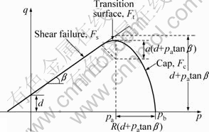
Fig.1 Yield surface of Drucker-Prager-Cap model in p-q plane
According to the mass conservation, the relative density is related to the volumetric plastic strain that is ρ=ρ0exp(εvp), where ρ and ρ0 are the actual relative density and the initial relative density of the sample, respectively, and relative density is the ratio of the density of porous sample to that of fully dense material. The equation is used to compute the revolution of the relative density during CIP process.
3 Experimental
The stainless steel powder AISI304 was used, which was supplied by Beijing Dyna-Veriex Co., Ltd. Its chemical composition is shown in Table 1 and the mean size is about 75 μm. Firstly, specimens were made by the SLS machine HRP-IIIA which was developed by Huazhong University of Science and Technology, China. The preforms were made by the AISI304 powder and coated by epoxy powder which were structure material and binder, respectively. The process parameters were as the same as those in Ref.[14]. Secondly, the polymer of low melt point was removed by degreasing at 900 °C in a vacuum furnace for 2 h. Thirdly, those samples were dipped into the latex of national rubber and heated at 90 °C for 1 h to make the rubber solidify and cross link which is shown in Fig.2. Lastly, those samples were CIPPed to increase the density.
Table 1 Composition of AISI304 stainless steel powder (mass fraction, %)
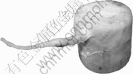
Fig.2 Cylinder component coated with rubber bag
Additionally, the CIP experiments were performed to obtain the volumetric hardening law that is the curve of pressure versus volumetric plastic strain. The definition of volumetric plastic strain is εvp=ε11+ε22+ε33, where ε11, ε22 and ε33 are true strain values. The volumetric plastic strains were measured at various pressures that are shown in Fig.3. This curve can be used to describe the volumetric hardening property of the material and be input to ABAQUS as material parameters.
4 Simulations
4.1 Results of simulations ignoring friction
CIP simulations of a cylindrical specimen were performed using the commercial finite element code ABAQUS/Explicit. The material was modeled with Drucker-Prager-Cap model. The initial height of the cylinder was 46.26 mm and the initial diameter was 39.81 mm. A 4-node bilinear axisymmetric element was used to discrete the solid model. The upper half of the height was modeled because of the symmetry of the model. The bag with 1.2 mm in thickness was coated on the outer surface of the cylindrical model, as shown in Fig.4, where the x axis is symmetric axis. The initial relative density of the parts was 0.49. The pressure was 400 MPa to be applied to the free surface of the bag. The volumetric hardening law of the metal powder came from the CIP experiments. The other parameters referred to Ref.[15] where d=0.1 Pa, β=15.64, R=0.23.
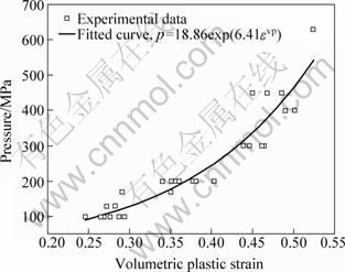
Fig.3 Curve of volumetric plastic strain versus pressure for 304 stainless steel powder (εvp is volumetric plastic strain; p is pressure)
The model after CIP is shown in Fig.5 where the finite element mesh is revolved about the symmetry axes to visualize the specimen. The deformation of the green bag on right upper corner is obvious because of the effect of corner. However, the deformation of the yellow component is small and limited to the local area and the distortion is not large. The deformation results after unloading is shown in Fig.6. The model sprang back due to the remove of the pressure. The effects of the bag on the results could be further shown in Fig.7. Three elements, No.58 (in the middle of the specimen), No.725 and No.697 (close to the side wall of the specimen) shown in Fig.4 are used to show changes of the equivalent plastic strain during the densification. The changes of elements No.725 and No.58 are almost the same. This indicates the equivalent plastic strain through the specimen is uniform. The change of equivalent plastic strain at element No.697 is some smaller than at the other two elements because of its large deformation of right upper corner. The comparisons of experimental results and calculated results are indicated in Table 2. The relative errors of simulations and experiments are -3.5% in height and 0.6% in diameter. The reason may be the error of dimension measurements and material parameters. Considering the errors of computations, the results are reasonable and acceptable.
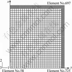
Fig.4 Cylindrical model in x-y plane before cold isostatic pressing
The shear strain contour is shown in Fig.8. The values are basically uniform on the whole model except the right upper corner. The contour of relative density shown in Fig.9 is similar to that of shear strain. The relative density of the upper right corner is a little smaller than that of the main area that is from 0.761 2 to 0.774 3. Simulative result are close to the experimental result of 0.74. So the results show that the rubber bag has little effect on final dimensions as the rubber bag material is soft compared with the selective laser sintered specimen which indents the bag[5].
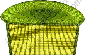
Fig.5 Cylindrical model after cold isostatic pressing

Fig.6 Cylindrical model after unloading
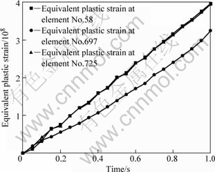
Fig.7 Curves of equivalent plastic strain versus time at three elements
Table 2 Key dimensions of cylinder before and after cold isostatic pressing
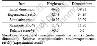
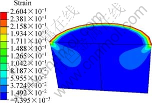
Fig.8 Shear strain contour of cylindrical specimen after cold isostatic pressing (bag is not displayed)

Fig.9 Relative density contour of cylindrical specimen after cold isostatic pressing (bag is not displayed)
4.2 Influence of friction coefficient
The influence of friction coefficient between specimen and bag is studied. According to Ref.[16], the friction coefficient between solids that we usually meet is neither zero nor infinite. It is in a small range of 0.2-0.5. So we set friction coefficient between the cylinder and the bag to be 0.1-0.8. The height of the cylinder was increased by 0.05 mm when the friction coefficient increased from 0 to 0.1, as shown in Fig.10. When the friction coefficient further added, the height would fluctuate in a small range (about 0.002 mm). So the friction coefficient has also little effect on the height. The fluctuation may be the results from the error of the numerical computation. On the other hand, the diameter decreased when the friction coefficient increased from 0 to 0.6. The total fluctuation in diameter is less than 0.01 mm, implying that the effect of the friction coefficient is still very small. The shear stress is small in CIP process which hardly makes the bag and component slide. So it is reasonable assumption that the bag is stick perfectly into the component without any sliding and the friction coefficient is null.
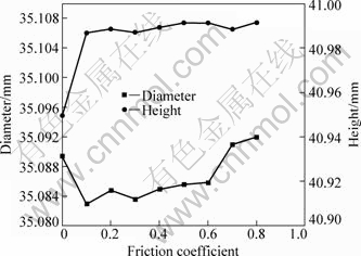
Fig.10 Curves of diameter and height of cylinder versus friction coefficient
5 Conclusions
1) The simulative results and experimental results have a general accord, indicating that the Drucker-Prager-Cap model is an effective model to simulate CIP process.
2) The results show that the bag has little effect on the simulations. So the shape of the bag changes with the selective laser sintered part.
3) The change value of the friction coefficient is very small. When friction coefficient is not null, its effect on the results has no obvious tendency.
4) If the combined SLS-CIP method is used to form titanium alloy and superalloy, hot isostatic pressing may be needed to be used in order to increase its density.
References
[1] KRUTH J P, LEVY G, KLOCKE F, CHILDS T H C. Consolidation phenomena in laser and powder-bed based layered manufacturing [J]. Annals of the CIRP, 2007, 56(2): 730-759.
[2] ABE F, OSAKADA K, SHIOMI M. The manufacturing of hard tools from metallic powders by selective laser melting [J]. J Mater Process Technol, 2001, 111: 210-213.
[3] LI S B, LI G A, LOU Y L, LUO H Q. Computer simulation of hot isostatic pressing densification and its application in TZP ceramics [J]. J Inorg Mater, 2000, 15: 324-330.
[4] SZANTO M, BIER W, FRAGE N, HARTMANN S, YOSIBASH Z. Experimental based finite element simulation of cold isostatic pressing of metal powders [J]. Int J Mech Sci, 2008, 50(3): 405-421.
[5] HERDERSON R J, CHANDLER H W, AKISANYA A R, BARBER H, MORIARTY B. Finite element modeling of cold isostatic pressing [J]. J Eur Ceram Soc, 2000, 20: 1121-1128.
[6] KIM K T, LEE S C, RYU H S. Densification behavior of aluminum alloy powder mixed with zirconia powder inclusion under cold compaction [J]. Mater Sci Eng A, 2003, 340: 41-48.
[7] REITERER M, KRAFT T, JANOSOVITS U, RIEDEL H. Finite element simulation of cold isostatic pressing and sintering of SiC components [J]. Ceram Int, 2004, 30: 177-183.
[8] SVOBODA A, HAGGBLAD H A, NASSTROM M. Simulation of hot isostatic pressing of metal powder components to near net shape [J]. Engn Comput, 1996, 13(5): 13-37.
[9] YUAN W X, MEI J, SAMAROV V, SELIVERSTOV D, WU X. Computer modelling and tooling design for near net shaped components using hot isostatic pressing [J]. J Mater Process Technol, 2007, 182: 39-49.
[10] KHOEI A R, AZAMI A R, AZIZI S. Computational modeling of 3D powder compaction processes [J]. J Mater Process Technol, 2007, 185: 166-172.
[11] SZANTO M, BIER W, FRAGE N, HARTMANN S, YOSIBASH Z. Experimental based finite element simulation of cold isostatic pressing of metal powders [J]. Int J Mech Sci, 2008, 50: 405-421.
[12] SHI Y S, REN L H, WEI Q S, LIU J H. Simulation of cold isostatic pressing of part by selective laser sintering [J]. Journal of Huazhong University of Science Technology: Nature Science, 2007, 35(12): 91-94. (in Chinese)
[13] HIBBITT B. ABAQUS theory manual [M]. Netherland: Elsevier Science Ltd, 1996.
[14] LIU J H, SHI Y S, LU Z L, HUANG S H. Manufacturing near dense metal parts via indirect selective laser sintering combined with isostatic pressing [J]. Appl Phys A, 2007, 89: 743-748.
[15] CHTOUROU H, GUILLOT M, GAKWAYA A. Modeling of the metal powder compaction process using the cap model. Part I. Experimental material characterization and validation [J]. Int J Solids Struct, 2002, 39: 1059-1075.
[16] DING Yi. Tribology [M]. Beijing: Science Press, 1978: 56. (in Chinese)
选择性激光烧结零件的冷等静压塑性成形过程模拟
杜艳迎,史玉升,魏青松
华中科技大学 材料成形与模具技术国家重点实验室,武汉 430074
摘 要:应用结合的选择性激光烧结和冷等静压技术快速制造金属零件。使用有限元方法预测零件的最终尺寸并降低成本;使用Drucker-Prager-Cap模型在ABAQUS软件中实现对选择性激光烧结零件的冷等静压过程的模拟。金属粉末的性质通过冷等静压实验测量。结果表明:橡胶包套和摩擦因数对零件的形状和尺寸影响很小;零件只有均匀收缩,没有明显的形状扭曲。实验与模拟结果符合得较好,这表明Drucker-Prager-Cap模型是模拟冷等静压过程的有效模型;通过模拟可以为选择性激光烧结零件的冷等静压成形过程提供有益的指导。
关键词:冷等静压;不锈钢;塑性成形;模拟
(Edited by YANG Hua)
Foundation item: Project(2007AA03Z115) supported by the High-Tech Research and Development Program of China
Corresponding author: DU Yan-ying; Tel: +86-27-63053169; E-mail: jenny_dyy@sina.com
DOI: 10.1016/S1003-6326(11)60830-3

