
Influencing factors of surface roughness of MAO ceramic coating on AZ91D
DI Shi-chun (��ʿ��), PAN Ming-qiang (����ǿ), CHI Guan-xin (�ٹ���)
School of Mechatronics Engineering, Harbin Institute of Technology, Harbin 150001, China
Received 28 July 2006; accepted 15 September 2006
Abstract��To investigate the treating parameters�� influence on the surface roughness of the MAO ceramic coating on AZ91D, experiments were implemented in the alkaline electrolyte by using a pulse power source with positive and negative pulse, and the surface roughness was measured and analyzed by using a Times roughness-meter and an optical microscope. The machining parameters�� influencing rule on the coating surface roughness was investigated. The result indicates that the influence of all parameters is interactive, while the positive voltage and the electrolyte concentration, or increasing the frequency and the positive and negative voltage ratio are appropriate, the coating surface roughness will be improved.
Key words: magnesium alloy; AZ91D; treating parameter; surface roughness; MAO ceramic coating
1 Introduction
Magnesium is the lightest structural metal, and has excellent physical and mechanical properties[1]. It has been recently used in many industries where A-alloy was traditionally the material of choice. However, magnesium alloy also exhibits serious drawbacks caused by its high chemical activity, poor corrosion resistance and friction and anti-wear behavior. It is certainly noticeable that the widespread use of magnesium alloy has promoted the development of the surface science and technology[2-3]. During the past decades, many coating technologies for protecting magnesium and its alloy have emerged. Micro-arc oxidation is a relatively new surface treatment technique, which is used to generate ceramic coatings on the surface of the valve metals[4]. In the last decade some scholars have gained significant achievements. However, much attention has been given to the structural, mechanical, thermal and electrical properties of MAO coatings[2,5-6], but few studies have focused on the coating surface roughness.
It is significant to investigate the influence factors of the ceramic coating surface roughness, understand and control the surface roughness, for the purpose to obtain the coating with good surface property. In this present work, the influencing factors of MAO coating surface roughness on AZ91D were researched.
2 Experimental
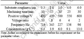
The die-cast AZ91D magnesium alloy was used as the substrate material in this present study. Its chemical composition (mass fraction, %) was: Al 8.5-9.5, Zn 0.5-0.9, Mn 0.17-0.40, Si��0.05, Fe��0.004, Cu��0.015, Ni��0.001, Mg balance. Samples, a shape of plate with thickness of 2 mm and side surface of 8-12 cm2, were performed according to the parameters in Table 1 by the pulse power source with positive and negative pulse in the alkaline electrolyte composed of MDS2*. During the treatment, the electrolyte temperature was below 15 ��, and the cathode and anode, respectively. Prior to the experiments, the samples were divided into 5 grades depending on their surface roughness. When the treatment finished, the Times roughness-meter and the optical microscope were used to measure and analyze the surface roughness of the ceramic coating.
Table 1 Experimental parameters
3 Results and discussion
3.1 Influence of substrate surface roughness
Fig.1 shows the changing rule of the coating surface roughness (Ra) that caused by the substrate surface. The treating parameters except sample surface roughness are presented in the 3rd column of the Table 1. When the sample��s surface roughness increases, the coating surfaces roughness increases too. The difference of the surface roughness between the sample and the coating decreases gradually. The research result indicates the coating surface roughness depends on the sample surface microstructure and the size of the particles and crater-like generated during the process of MAO. Under the same treating conditions, it mainly depends on the former because the diameter of the particle and crater-like is the same, about 2 ��m. With increase of the sample surface roughness, it becomes more and more difficult that the particle and crater-like improve the roughness because they only cover on the surface.
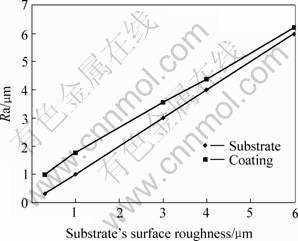
Fig.1 Influence of coating surface roughness on coating surface roughness
3.2 Influence of machining time
Fig.2 shows the relationship between the coating surface roughness with the machining time on the Ra=0.3, 4.0 and 6.0 samples surface. The treating parameters except machining time are presented in the 2nd, 5th and 6th column of the Table 1. From Fig.2, all coating surface roughness of three groups increases gradually, when the machining time increases. And an interesting result can also be found that the increase rate of the coating surface roughness before 20 min is more rapid than that after 20 min.
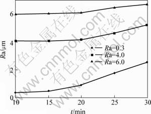
Fig.2 Influence of machining time on coating surface roughness
When the machining time is less than 20 min the changing of the coating surface roughness is not obvious. In fact, when the samples are treated for 10 min, the white discharge sparks are very small and uniformly distributed, and the substrate is only covered by the thin transparent passive coating and loses their metal brightness, because the spark energy is not enough. When the machining goes on, the discharge spark number begins to decrease, its color is transformed from white to red, and the size and energy of the single discharge spark are enlarged. When the machining time exceeds 20 min, the particle and crater�Clike grow up gradually and their size is more than 2 ��m. In the same time, the transparent passive coating begins to transform into the ceramic coating, and then the influence of the particle and crater�Clike on the coating surface roughness increases, and becomes the main factor. And the coating surface roughness will increase when prolonging the machining time.
3.3 Influence of electrolyte concentration
Fig.3 shows the changing rule of the coating surface roughness affected by the electrolyte concentration. The treating parameters except electrolyte concentration are presented in the 3rd column of the Table 1. As shown in Fig.3, the coating surface roughness reduces at the beginning when increasing the electrolyte concentration, and it increases rapidly when the concentration is more than 6 g/L. And when the concentration is 6 g/L, the Ra value is the least, about 3.5 ��m. During treating under the constant voltage the electrolyte concentration can influence the machining positive current. When the energy density is not enough, the discharge spark only turns out on the substrate��s convex, even the smaller convex, prior to the other place, because of the point discharge. The research result indicates the particle and cater-like are irregularly distributed on the surface treated in the electrolyte of 1.3 g/L, and uniformly distributed in the electrolyte of 6 g/L. When the concentration exceeds 6 g/L, the coating surface roughness begins to increase rapidly owing to the size of the particle and cater-like increases that caused by increasing energy density.
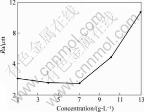
Fig.3 Influence of electrolyte concentration on coating surface roughness
3.4 Influence of electrical parameters
The positive voltage of single pulse, the voltage ratio of positive to negative, and the frequency, directly influence on the coating surface roughness because they directly determine the discharge spark energy. And the negative voltage can influence the coating breakdown under the condition of constant positive voltage. The changing rule of the coating surface roughness can be seen from Figs.4-6. The treating parameters for No.1 group and No.2 group except the positive voltage are presented in the 2nd and 3rd column of the Table 1, respectively. Fig.5 and Fig.6 are presented in the 3rd column of the Table 1 except the frequency and the positive to negative voltage, respectively.
From Fig.4, the surface roughness of the two groups decreases at the beginning with the positive voltage increases, and then it increases rapidly. When the positive voltage is above 500 V the surface roughness is the best. These are like to the influence of the electrolyte concentration. As shown in Fig.5, the surface roughness decreases rapidly at the beginning while the frequency increases, and then trends to be constant because the size of the particle and carter-like increase quickly while the frequency decreases. In the contrary, the size will become small, even the coating is only the passive layer and can not form the ceramic coating, because the lasting time of the discharge spark is too short. This phenomenon is very obvious when the coating treated by the frequency of 714 Hz. Therefore the surface roughness hardly changes when the frequency continues to increase.
From Fig.6, the changing rule influenced by the voltage ratio of positive to negative is like that by the frequency. But the ratio affects the coating breakdown by changing the negative positive. The smaller the ratio value is, the easier the coating is to be broken. The experiment indicates that the coating treated at the ratio of 2 is the easiest to be broken than that at the other ratio. If the ratio exceeds limit value, the craterlet may be generated on the sample initial surface. This result happens when the coating is treated by the ratio of 10. These mean that the ratio should be chosen appropriately.
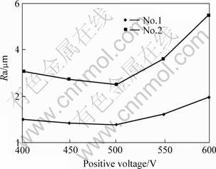
Fig.4 Influence of positive voltage on coating surface roughness

Fig.5 Influence of frequency on coating surface roughness
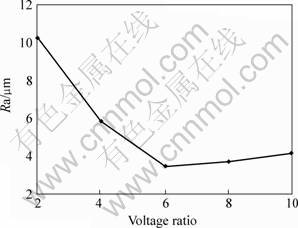
Fig.6 Influence of voltage ratio of positive to negative on coating surface roughness
4 Conclusions
1) The experimental result demonstrates that the influence of the technique parameters on the coating surface roughness is very obvious, and the influence of every parameter is different and interactive. With the decreasing substrate surface roughness, coating surface roughness will improve. When the machining time prolongs, the roughness of coating continues to increase. While the positive voltage, the electrolyte concentration, and the voltage ratio of positive to negative are appropriate, the best coating surface roughness will be gained. With the increasing frequency, the coating will improve.
2) The best surface roughness can be gained by adjusting the parameters to some extent. When the treating parameters are set as follows: the machining time is 20 min, the positive voltage is 500 V, the voltage ratio of positive to negative is 6, the frequency is 227 Hz, the electrolyte concentration is 6 g/L and the surface roughness of substrate is 0.3 ��m, the coating with Ra 0.8 ��m roughness will be gained.
Acknowledgments
The work was supported by the Innovation Fund for Small Technology-based Firms for Harbin Di Si Numerical Control Equipment Co., Ltd. Samples, the MAO equipment and chemicals were provided by company. The authors express thanks to the technical staffs of the company for their useful helps and advices.
MDS2* is the chemicals invented to treat Mg by company.
References
[1] MORDIKE B L, EBERT T. Magnesium properties �C applications �C potential[J]. Mater Sci Eng A, 2001, A302: 37-45.
[2] YEROKHIN A L, SHATROV A, SAMSONV V, SHASHKOV P, LEYLAND A, MATTHEWS A. Fatigue properties of Keronite coatings on a magnesium alloy[J]. Surface and Coatings Technology, 2004, 182: 78-84.
[3] VERDIER S, BOINET M, MAXIMOVITCH S, DALARD F. Formation, structure and composition of anodic films on AM60 magnesium alloy obtained by DC plasma anodizing[J]. Corrosion Science, 2005, 47: 1429-1444.
[4] RUDNEV V S, YAROVAYA T P, BOGUTA D L, TYRINA L M, NEDOZOROV P M, GORDIENKO P S. Anodic spark deposition of P, Me(II) or Me(III) containing coatings on aluminium and titanium alloys in electrolytes with polyphosphate complexes[J]. Journal of Electroanalytical Chemistry, 2001, 497: 150�C158.
[5] GUO X W, DING W J, LU C, ZHAI C Q. Influence of ultrasonic power on the structure and composition of anodizing coatings formed on Mg alloys[J]. Surface and Coating Technology, 2004, 183: 359-368.
[6] HOCHE H, SCHEERER H, PROBST D, BROSZEIT E, BERGER C. Development of a plasma surface treatment for magnesium alloys to ensure sufficient wear and corrosion resistance[J]. Surface and Coating Technology, 2003, 174/175: 1018-1023.
(Edited by YANG Hua)
Corresponding author: PAN Ming-qiang; Tel: +86-451-86413834; E-mail: pmqwl@163.com

