A356合金重力铸造凝固过程的空间界面传热行为与表面特征
来源期刊:中国有色金属学报(英文版)2019年第1期
论文作者:林嘉华 赵海东 黄嘉敏
文章页码:43 - 50
关键词:A356合金;凝固;界面传热系数;热传导反算法;表面特征
Key words:A356 alloy; solidification; interfacial heat transfer coefficient; inverse heat conduction problem; surface characteristics
摘 要:铸件/铸型界面传热系数是影响凝固过程温度场分布的重要因素。基于改进的非线性估算法,结合A356合金重力铸造凝固过程底部与侧部界面的温度测量,利用有限元法逆向求解界面传热系数的变化。结果表明:当铸件底部形成凝壳后,该界面的传热系数达到稳定;而侧部界面的传热系数稳定阶段发生在铸件体收缩完成时;底部界面传热系数的稳定值为750 W/(m2?°C),约为侧部界面的3倍。此外,铸件底部与侧部界面的表面形貌分析表明,凝固过程表面特征的演变导致空间界面传热系数的差异。
Abstract: As one of the key boundary conditions during casting solidification process, the interfacial heat transfer coefficient (IHTC) affects the temperature variation and distribution. Based on the improved nonlinear estimation method (NEM), thermal measurements near both bottom and lateral metal-mold interfaces throughout A356 gravity casting process were carried out and applied to solving the inverse heat conduction problem (IHCP). Finite element method (FEM) is employed for modeling transient thermal fields implementing a developed NEM interface program to quantify transient IHTCs. It is found that IHTCs at the lateral interface become stable after the volumetric shrinkage of casting while those of the bottom interface reach the steady period once a surface layer has solidified. The stable value of bottom IHTCs is 750 W/(m2?°C), which is approximately 3 times that at the lateral interface. Further analysis of the interplay between spatial IHTCs and observed surface morphology reveals that spatial heat transfer across casting-mold interfaces is the direct result of different interface evolution during solidification process.
Trans. Nonferrous Met. Soc. China 29(2019) 43-50
Jia-hua LIN, Hai-dong ZHAO, Jia-min HUANG
National Engineering Research Center of Near-net-shape Forming for Metallic Materials, South China University of Technology, Guangzhou 510641, China
Received 1 January 2018; accepted 26 April 2018
Abstract: As one of the key boundary conditions during casting solidification process, the interfacial heat transfer coefficient (IHTC) affects the temperature variation and distribution. Based on the improved nonlinear estimation method (NEM), thermal measurements near both bottom and lateral metal-mold interfaces throughout A356 gravity casting process were carried out and applied to solving the inverse heat conduction problem (IHCP). Finite element method (FEM) is employed for modeling transient thermal fields implementing a developed NEM interface program to quantify transient IHTCs. It is found that IHTCs at the lateral interface become stable after the volumetric shrinkage of casting while those of the bottom interface reach the steady period once a surface layer has solidified. The stable value of bottom IHTCs is 750 W/(m2・°C), which is approximately 3 times that at the lateral interface. Further analysis of the interplay between spatial IHTCs and observed surface morphology reveals that spatial heat transfer across casting-mold interfaces is the direct result of different interface evolution during solidification process.
Key words: A356 alloy; solidification; interfacial heat transfer coefficient; inverse heat conduction problem; surface characteristics
1 Introduction
Heat transfer behavior plays a key role in solidification process and determines cooling conditions within the casting, especially in foundry systems with high thermal diffusivity such as castings with metallic mold [1,2]. High heat transfer can induce fine microstructure and therefore good mechanical properties and high productivity of castings [3]. The behavior between the casting and mold or die interface could be characterized by interfacial heat transfer coefficient (IHTC) quantitatively, given by
 (1)
(1)
The accurate data of IHTC are helpful in improving the accuracy of casting numerical simulation. Several investigations have been carried out in this field, and the results have shown that IHTC is a function of many variables in the casting process [4-6] including the presence and thickness of surface coatings, casting geometry and size, alloy type and composition, mold temperature, and pouring temperature, etc. There are two main approaches to quantify IHTC [7,8]: (1) counting with the size of interface air gap measured by displacement sensor and hence calculating IHTC directly; (2) measuring temperature history with thermocouples placed in the cast and mold and inversely calculating the IHTC by numerical calculation. The latter method was advanced by BECK [9], well-known as nonlinear estimation method (NEM). It is simple in concept and does not change the problem physical essentials since the measurements in the distant future do not change the ‘present’ estimations [10].
Transient IHTCs are sensitive to an evolutionary interface and could inspect the highly dynamic interface conditions with time [11,12]. Almost all studies have been devoted to determining IHTC or heat flux assuming a one-dimensional problem at the casting-mold interface for simplicity [1-5,7,12,13]. However, the interfacial heat transfer is multi-dimensional in actual condition. MALINOWSKI et al [14] developed a dedicated FE model based on nonlinear shape function to identify the three-dimensional distribution of HTC over a cooled surface for a heat removal problem. The only study on spatial heat transfer in casting process was reported by ARUNKUMAR et al [15]. They pointed out that due to the spatial variation of air gap formation caused by filling transients, the heat flux at the metal-mold interface reaches peak values at different times along different segments of the mold wall, anticipating the complex nature of heat transfer at the metal-mold interface. As well known, the IHTC should be related to the interface change, which also results in various surface characteristics. Unfortunately, the relationship between the IHTC and surface characteristics has not been reported to date.
In the present work, the NEM of binary version was developed and a corresponding program was designed for quantifying transient values of IHTC between the casting and die at bottom and lateral interfaces. The characterizations of calculated IHTCs were analyzed, and their differences were pointed out. The casting surface characteristics on both interfaces were inspected and compared. Furthermore, the relations between the characteristics and evolution of IHTCs were investigated.
2 Experimental
The casting and mold materials are A356 alloys and H13 steel, respectively. Their thermo-physical properties employed in the inverse calculation are summarized in Table 1.
Table 1 Thermo-physical properties of A356 and H13 [16]
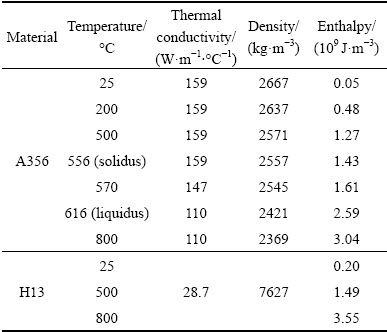
Figure 1 presents the casing assembly used in the solidification experiments. The geometry of casting was a d60 mm × 60 mm cylinder and the cavity filling was of a downhill type under gravity condition. In the experiment, seven thermocouples were used to measure the temperature evolution in casting and mold. They are labeled TC1-TC7 in Fig. 1. All the thermocouples used were K-type thermocouples with 0.5 mm external diameter. A specific insert, equipped with the mold via screw thread, was developed to accommodate thermocouples through d60 mm holes to ensure the accurate distance between the measurement points and casting-mold interface. Three thermocouples were placed near the bottom interface, where TC1 was located at the casting side (2 mm from the interface) while TC2 and TC3 were located at the mold side (2 and 4 mm from the interface, respectively). Similarly, TC4, TC5 and TC6 were set at the lateral interface. The temperature of the center was monitored by TC7. The thermocouples were connected to the transmitters (MSTS-24-R/K, M-System), which was extended to a data-logger (CoMo Injection Type 2869B, Kistler) by electromagnetic shielding cable. The logger recorded the thermal histories at the seven points in the casting and mold every 0.1 s automatically once a starting signal was triggered.

Fig. 1 Schematics of casting system and temperature measurement (unit: mm)
The time-dependent temperature profiles of TC1-TC6 from the experiment were incorporated into the designed computer program. Hence, the IHTC curves against time could be calculated with an algorithm based on NEM (details in Section 3).
After the casting experiment, the samples for characteristics observation of bottom and lateral surfaces were obtained from the portions close to the measured points. The morphologies of both surfaces were inspected with a Super-depth digital microscope (VHX-1000E, Keyence). The properties of two surfaces such as altitude difference were obtained and discussed.
3 Mathematical model
3.1 Heat transfer model
The solidification process can be described as a transient heat-conduction model with latent heat, which could be depicted in cylindrical coordinate as [17]
 (2)
(2)
The initial and boundary conditions are prescribed as
T(R, z)=T0, at t=0 (3)
 , on symmetry or insulation boundary (4)
 , on convection boundary (5)
 , at casting-mold interface (6)
The initial temperature (610 °C) monitored by TC7 was set as T0. The convection coefficient (hc) was set to be 20 W/(m2・°C) [16].
The enthalpy equation was adopted for the liberation of the latent heat of fusion:
 (7)
(7)
Then, Eq. (2) could be written as
 (8)
(8)
Utilizing the FEM to discrete Eq. (8), the following equation is obtained:
 (9)
(9)
The heat transfer inside the mold is similar, which was stated in our previous work [11].
3.2 Inverse solution
The principle of inverse algorithm adopted in this work is based on the approach for solving the IHCP, called “the function specification method” [10].
It was assumed that IHTCs are equal in the current (Lth) time interval:
hL=hL+i (i=1, 2, …, r-1) (10)
Principally, the inverse method is to minimize an objective function defined by the following equation in the Lth time interval:
 (11)
(11)
With respect to increment change in h (IHTC),  could be differentiated based on Taylor expansion, written as

 (12)
(12)
where
△h=h*-h (13)
 is usually defined as the sensitivity coefficient [18,19], calculated by
 (14)
(14)
and
 (15)
(15)
where ε is set to be 0.001.
FL(hR, hz) achieves its minimum value when
 (16)
(16)
and
 =0 (17)
Introducing Eqs. (12)-(15) into Eqs. (16) and (17) yields
 (18)
(18)
and
 (19)
(19)
where
 (20)
(20)
 (21)
(21)
 (22)
(22)
 (23)
(23)
 (24)
(24)
During each time interval, △hR and △hz at two different interfaces (i.e. bottom and lateral interfaces) were computed for several times until
 (25)
(25)
and
 (26)
(26)
Therefore, the transient IHTCs for every time interval were estimated according to the above algorithm. It should be noted that the equations for IHTC increment, Eqs. (18) and (19), are more complicated than those in previous works [1-3,18], which have taken thermal interference effect between two interfaces into consideration for two-dimensional cases as given by Eq. (22). Therefore, differences of interfaces can be compared, which can provide important information for channel cooling design in dies. In addition, modified values of hR and hz are calculated iteratively for each time step until satisfying prerequisites of Eqs. (25) and (26) simultaneously. This increases the difficulty in numerical iteration. Under the convergence condition, the judgment factor E on the right side of the inequalities (Eqs. (25) and (26)) remains at 0.01 throughout the inverse solution. Figure 2 gives the flowchart procedure to solve this inverse heat conduction problem. The transient thermal field for iterations is calculated by FEM software ANSYS.
4 Results and discussion
4.1 Spatial interface heat transfer
During the solidification of A356 alloy, measured temperatures versus time at TC1-TC7 are given in Fig. 3. The temperatures of TC1 and TC4 in castings showed little difference. But the temperatures of TC2 and TC3 in die near bottom surface were higher than those of TC5 and TC6 near lateral interface, indicating that the heat flux in former interface was higher.
The thermal histories of TC1-TC6 (N=3 for each interface in Eq. (11) in Fig. 3 were then applied to calculating the IHTCs at two interfaces. In the calculation, the number of future times r in Eq. (10) was set to be 5; the time interval was 1 s; the initial IHTC for NEM program start was set to be 4000 W/(m2・°C) for both interfaces. The calculated transient IHTCs of bottom and lateral interface corresponding to each time interval are plotted in Fig. 4. Accordingly, during the casting solidification, the IHTC values firstly went up dramatically after pouring and reached a peak or maximum value, and then dropped gradually to the stable stage.

Fig. 2 Flow chart of IHTC calculation with inverse method

Fig. 3 Measured temperature profiles of TC1-TC7

Fig. 4 Calculated IHTCs of bottom and lateral interfaces against solidification time
Contributing to good contact of liquid A356 with die surface at initial solidification, the IHTCs at the bottom and lateral interfaces reached their maximum values, about 3100 and 2100 W/(m2・°C), respectively. The IHTC curve of the lateral interface showed a progressive upward trend in the initial stage, which was similar with our previous work [11]. However, serious fluctuation of IHTC of the bottom interface was observed from 0 to 10 s period. Similar phenomena have been found in Ref. [4] with a downhill casting but not reported in literatures [1,5,13] with lateral cases. As well known, IHTC is sensitive to the interface condition. At the early stage of casting, when the liquid metal contacted with bottom die resulting in high cooling rate and solidification, shrinkage would immediately occur and increase the gap between casting and die at the interface. This decreased the IHTC. But in this period, the solidified shell was very thin, and was of high temperature and low strength. Under the hydrostatic pressure of liquid metal, the shell might deform, improving surface conformity at the interface and resulting in an increased value of IHTC [12]. Therefore, the fluctuating values at bottom interface were consequences of the interplay between solidification shrinkage of high cooling and deformation of solidified thin shell with high temperature.
As solidification progressing, an imperfect junction was formed at the casting-mold interface due to a reduction in plasticity of the solidified layer and an increase of its thickness [19]. These factors increased the bending resistance of the solidified shell, and the pressure from the mushy and liquid metal became insufficient to maintain a confirm contact between the casing and mold surface [13], which had an adverse effect on interfacial heat conduction. In result, both the IHTCs in Fig. 4 dropped after their peak value periods.
To further make sense of the change of IHTCs, the change rates of IHTCs were calculated and shown in Fig. 5. For the bottom surface, it is shown that the IHTC decreased from 5 to 17.5 s and its stable value is about 750 W/(m2・°C). It can be known from Fig. 3 that at 17.5 s, the temperature measured at TC1 is below 556 °C (solidus of A356), implying a solidified shell with thickness of over 2 mm had formed since TC1 was set at the casting side, 2 mm from the casting-mold interface. After the time, the IHTC values showed very small variation, which means that the bottom interface had come up to a rather stable condition.

Fig. 5 Rate of change of IHTC at two interfaces of casting
As for the lateral interface, the IHTC values decreased from 7 to 32 s, as shown in Fig. 5, lasting longer time than that of the bottom interface. The stable IHTC of the former, approximately 250 W/(m2・°C), is only one-third that of latter interface, as can be seen in Fig. 4. This is related to the effect of casting surface characteristics on interfacial heat transfer. Figure 3 shows that the measured temperature of TC4 reaches the solidus temperature at 14 s. However, according to Figs. 4 and 5, the IHTC value of lateral interface still decreased even the casting surface, which contacted against the interface, had solidified. It is interesting that at the moment of 32 s, the temperature measured by TC7 dropped to 561 °C, which is coincided with 560.8 °C, the temperature with the maximum shrinkage of the Al-7%Si-0.4%Mg alloys reported by STANGELAND et al [20]. Since the TC7 is located in the casting center, it can be considered that the casting solidification shrinkage ended at certain temperature or time. The results show that the IHTC at lateral interface has stable value after the volumetric solidification shrinkage of casting.
Since the thermal history of TC7 had not been adopted in the proposed inverse calculation, a comparison of the measured and simulated temperatures of this measuring point is shown in Fig. 6. An acceptable agreement is obtained, the maximum relative deviation between them is 2.6%, which may be owing to the normally constant treatment and simple linear interpolation versus temperature of the thermo-physical parameters of this work. Recently, ZHANG et al [21] have pointed out that the estimation accuracy of the inverse method could be increased by 50% if the temperature dependence of the thermo-physical properties was fully considered.
4.2 Relation between surface characteristics and IHTC
Figure 7 shows the casting surface morphologies from two interfaces. It is found that in most observed regions on the casting bottom surface the convex parts have small sizes and are of scattered distribution, as shown in Fig. 7(a). Only few portions on this surface show morphology like Fig. 7(b). On the contrary, the convex parts with larger sizes are widely observed on the lateral surface (Figs. 7(c) and (d)).

Fig. 6 Comparison of measured and simulated temperature of TC7
It is also found that the maximum height differences on casting surface from bottom interface are 2.378 and 4.445 μm in the inspected portions, less than that from lateral interface (5.862 and 6.889 μm). For the bottom interface, the molten metal impacted the cold bottom surface of mold during casting pouring. This might bring about many nuclei there. In the later solidification, these nuclei grew fast and kept intimate contact with the surface. Consequently, many convex parts were formed on the corresponding casting surface (Fig. 7(a)). The liquid among these parts solidified later and should shrinkage. Since the liquid regions among the parts were of limited volume and the liquid fed the shrinkage downwards, the shrinkage of remained liquid was small. Hence, smaller height difference was formed on this surface. As for the lateral interfaces, the liquid Al flew along the die surface of interface, and hence fewer nuclei might generate. Therefore, the number of convex parts on corresponding casting surface was less. The liquids among the parts had larger volume, causing larger shrinkage. As a result, large height differences on the lateral surface are observed (Figs. 7(c) and (d)).

Fig. 7 Surface morphologies of casting from two interfaces
Once the casting-mold interfacial air gap develops, the heat transfer across the interface can be affected by three factors: (1) conduction through isolated metal- mold (solid-solid) contact, (2) conduction through gas (solid-gas-solid), and (3) radiation between the casting and mold surfaces. According to Fig. 7, it is considered that the heat transfer is dominated by factors (2) and (3) across the lateral interface while factors (1) and (2) play the main role at the bottom interface. The heat conduction of method (1) induced higher transfer efficiency than others. Although the conduction and radiation through the air gap existed at both interfaces, the gap at bottom interface is smaller than that at lateral interface, as shown in Fig. 7. Both resulted in a higher stable IHTC value at bottom interface in Fig. 4. The evolution of two interfaces during casting solidification is schematically illustrated in Fig. 8.

Fig. 8 Schematics of evolution of two casting-mold interfaces during solidification
5 Conclusions
(1) At bottom interface, the fluctuation of IHTCs is found during early stage of solidification. This is a direct consequence of solidification shrinkage of high cooling rate and deformation of solidified thin shell with high temperature and low strength. The former decreased IHTCs while the latter improved confirm contact of casting and mold, thus increasing IHTCs.
(2) The IHTCs of bottom interface reached the stable value since the casting surface from interface solidified, while those of lateral interface became stable at the end of volumetric solidification shrinkage of casting.
(3) Many convex parts and small height difference were found on the casting surface from bottom interface. On the contrary, the surface from lateral interface was characterized with large convex part and high difference. It is indicated that at the bottom interface, conduction played a main role in heat transfer and caused higher stable IHTCs.
Nomenclatures
c(T)
Specific heat capacity, J/(kg・°C)
E
Judgment factor
h
Interfacial heat transfer coefficient (IHTC), W/(m2・°C)
hc
Convection coefficient, W/(m2・°C)
h0
Assumed initial IHTC, W/(m2・°C)
hz
IHTC of the bottom interface, W/(m2・°C)
hR
IHTC of the lateral interface, W/(m2・°C)
△h
Increment of IHTC, W/(m2・°C)
△hz
Increment of IHTC at the bottom interface, W/(m2・°C)
△hR
Increment of IHTC at the lateral interface, W/(m2・°C)
H
Enthalpy, J/m3
n
Directional vector
N
The number of measurement points for each interface
q
Average heat flux across the interface, W/m2

Latent heat, W/m3
r
The number of future times
R
Radius, m
t
Time, s
T
Temperature, °C
TIC
Casting surface temperature, °C
TIM
Cavity surface temperature, °C
T∞
Ambient temperature, °C
Ts
Surface temperature, °C
T0
Pouring temperature, °C
Tm
Experimentally measured temperature, °C
Tc
Calculated temperature, °C
z
Height, m
[C]
Heat capacity matrix
[K]
Heat conduction matrix
{T}
Temperature array

Temperature transition rate array
{P}
Thermal load array
ε
A tiny quantity
ρ
Density, kg/m3
λ
Thermal conductivity, W/(m・°C)

Sensitivity coefficient
References
[1] SANTOS C A, SIQUEIRA C A, GARCIA A, QUARESMA J M V, SPIM J A. Metal-mold heat transfer coefficients during horizontal and vertical unsteady-state solidification of Al-Cu and Sn-Pb alloys [J]. Inverse Problems in Science and Engineering, 2004, 12: 279-296.
[2] FERREIRA I L, SPINELLI J E, PIRES J C, GARCIA A. The effect of melt temperature profile on the transient metal/mold heat transfer coefficient during solidification [J]. Material Science and Engineering A, 2005, 408: 317-325.
[3] BROUCARET S, MICHRAFY A, DOUR G. Heat transfer and thermo-mechanical stresses in a gravity casting die: Influence of process parameters [J]. Journal of Materials Processing Technology, 2001, 110: 211-217.
[4] HALLAM C P, GRIFFITHS W D. A model of the interfacial heat-transfer coefficient for the aluminum gravity die-casting process [J]. Metallurgical and Materials Transactions B, 2004, 35: 721-733.
[5] GRIFFITHS W D. Modelled heat transfer coefficients for Al-7wt.%Si alloy castings undirectionally solidified horizontally and vertically downwards [J]. Materials Science and Technology, 2000, 16: 255-260.
[6] PALUMBO G, PIGLIONICO V, PICCINNI A, GUGLIELMI P, SORGENTE D, TRICARICO L. Determination of interfacial heat transfer coefficients in a sand mould casting process using an optimized inverse analysis [J]. Applied Thermal Engineering, 2015, 78: 682-694.
[7] DOUR G, DARGUSCH M, DAVIDSON C, NEF A. Development of a non-intrusive heat transfer coefficient gauge and its application to high pressure die casting: Effect of the process parameters [J]. Journal of Materials Processing Technology, 2005, 169: 223-233.
[8] KORU M, SERCE O. Experimental and numerical determination of casting-mold interfacial heat transfer coefficient in the high pressure die casting of A-360 aluminum alloy [J]. Acta Physica Polonica A, 2016, 130: 453-458.
[9] BECK J V. Nonlinear estimation applied to the nonlinear inverse heat conduction problem [J]. Heat Mass Transfer, 1970, 13: 703-716.
[10] BECK J V, BLACKWELL B, HAJI-SHEIKH A. Comparison of some inverse heat conduction methods using experimental data [J]. Heat Mass Transfer, 1996, 39: 3649-3657.
[11] LI Jun-wen, ZHAO Hai-dong, WU Chao-zhong, LI Yuan-yuan. Interfacial heat transfer behavior of aluminum alloy during squeeze casting [J]. The Chinese Journal of Nonferrous Metals, 2014, 24: 2727-2734. (in Chinese)
[12] HO K, PEHLKE R D. Metal-mold interfacial heat transfer [J]. Metallurgical Transaction B, 1985, 16: 585-594.
[13] SANTOS C A, QUARESMA J M V, GARCIA A. Determination of transient interfacial heat transfer coefficients in chill mold castings [J]. Journal of Alloys and Compounds, 2001, 319: 174-186.
[14] MALINOWSKI Z, TELEJKO T, HADALA B, CEBO-RUDNICKA A, SZAJDING A. Dedicated three dimensional numerical models for the inverse determination of the heat flux and heat transfer coefficient distributions over the metal plate surface cooled by water [J]. International Journal of Heat and Mass Transfer, 2014, 75: 347-361.
[15] ARUNKUMAR S, RAO K V S, KUMAR T S P. Spatial variation of heat flux at the metal-mold interface due to mold filling effects in gravity die-casting [J]. International Journal of Heat and Mass Transfer, 2008, 51: 2676-2685.
[16] ZHU W, HAN Z, LIU B. Thermomechanical modeling of solidification process of squeeze casting II: Numerical simulation and experimental validation [J]. Acta Metallurgical Sinica, 2009, 45(3): 363-368. (in Chinese)
[17] LI C, THOMAS B G. Thermomechanical finite-element model of shell behavior in continues casting of steel [J]. Metallurgical and Materials Transaction B, 2004, 36: 1151-1172.
[18] KUMAR T S P, KAMATH H C. Estimation of multiple heat-flux components at the metal/mold interface in bar and plate aluminum alloy castings [J]. Metallurgical and Materials Transactions B, 2004, 35: 575-585.
[19] SPINELLI J E, CHEUNG N, GOULART P R, QUARESMA J M V, GARCIA A. Design of mechanical properties of Al-alloys chill castings based on the metal/mold interfacial heat transfer coefficient [J]. International Journal of Thermal Science, 2012, 51: 145-154.
[20] STANGELAND A, MO A, ESKIN D. Thermal strain in the mushy zone for aluminum alloys [J]. Metallurgical and Materials Transactions A, 2007, 37: 2219-2229.
[21] ZHANG A, LIANG B, GUO Z, XIONG S. Determination of the interfacial heat transfer coefficient at the metal-sand mold interface in low pressure sand casting [J]. Experimental Thermal and Fluid Science, 2017, 88: 472-482.
林嘉华,赵海东,黄嘉敏
华南理工大学 国家金属材料近净成形工程技术研究中心,广州 510641
摘 要:铸件/铸型界面传热系数是影响凝固过程温度场分布的重要因素。基于改进的非线性估算法,结合A356合金重力铸造凝固过程底部与侧部界面的温度测量,利用有限元法逆向求解界面传热系数的变化。结果表明:当铸件底部形成凝壳后,该界面的传热系数达到稳定;而侧部界面的传热系数稳定阶段发生在铸件体收缩完成时;底部界面传热系数的稳定值为750 W/(m2・°C),约为侧部界面的3倍。此外,铸件底部与侧部界面的表面形貌分析表明,凝固过程表面特征的演变导致空间界面传热系数的差异。
关键词:A356合金;凝固;界面传热系数;热传导反算法;表面特征
(Edited by Bing YANG)
Foundation item: Project (TC160A310-10-01) supported by the National Industry Base Enhanced Program, China; Projects (2015B090926002, 2013A090100002) supported by Science and Technology of Guangdong Province, China; Project (2016AG100932) supported by Key Technology Program of Foshan, China
Corresponding author: Hai-dong ZHAO; Tel: +86-13660333095; E-mail: hdzhao@scut.edu.cn
DOI: 10.1016/S1003-6326(18)64913-1

