Stress initialization methods for dynamic numerical simulation of rock mass with high in-situ stress
来源期刊:中南大学学报(英文版)2020年第10期
论文作者:刘科伟 杨家彩 李旭东 刘志祥
文章页码:3149 - 3162
Key words:in-situ stress; stress initialization method; dynamic disturbance; numerical simulation; rock mass
Abstract: In the context of deep rock engineering, the in-situ stress state is of major importance as it plays an important role in rock dynamic response behavior. Thus, stress initialization becomes crucial and is the first step for the dynamic response simulation of rock mass in a high in-situ stress field. In this paper, stress initialization methods, including their principles and operating procedures for reproducing steady in-situ stress state in LS-DYNA, are first introduced. Then the most popular four methods, i.e., explicit dynamic relaxation (DR) method, implicit-explicit sequence method, Dynain file method and quasi-static method, are exemplified through a case analysis by using the RHT and plastic hardening rock material models to simulate rock blasting under in-situ stress condition. Based on the simulations, it is concluded that the stress initialization results obtained by implicit-explicit sequence method and dynain file method are closely related to the rock material model, and the explicit DR method has an obvious advantage in solution time when compared to other methods. Besides that, it is recommended to adopt two separate analyses for the whole numerical simulation of rock mass under the combined action of in-situ stress and dynamic disturbance.
Cite this article as: YANG Jia-cai, LIU Ke-wei, LI Xu-dong, LIU Zhi-xiang. Stress initialization methods for dynamic numerical simulation of rock mass with high in-situ stress [J]. Journal of Central South University, 2020, 27(10): 3149-3162. DOI: https://doi.org/10.1007/s11771-020-4535-3.

J. Cent. South Univ. (2020) 27: 3149-3162
DOI: https://doi.org/10.1007/s11771-020-4535-3

YANG Jia-cai(杨家彩)1, LIU Ke-wei(刘科伟)1, 2, LI Xu-dong(李旭东)1, LIU Zhi-xiang(刘志祥)1
1. School of Resources and Safety Engineering, Central South University, Changsha 410083, China;
2. School of Civil and Resource Engineering, The University of Western Australia, Perth, Australia
 Central South University Press and Springer-Verlag GmbH Germany, part of Springer Nature 2020
Abstract: In the context of deep rock engineering, the in-situ stress state is of major importance as it plays an important role in rock dynamic response behavior. Thus, stress initialization becomes crucial and is the first step for the dynamic response simulation of rock mass in a high in-situ stress field. In this paper, stress initialization methods, including their principles and operating procedures for reproducing steady in-situ stress state in LS-DYNA, are first introduced. Then the most popular four methods, i.e., explicit dynamic relaxation (DR) method, implicit-explicit sequence method, Dynain file method and quasi-static method, are exemplified through a case analysis by using the RHT and plastic hardening rock material models to simulate rock blasting under in-situ stress condition. Based on the simulations, it is concluded that the stress initialization results obtained by implicit-explicit sequence method and dynain file method are closely related to the rock material model, and the explicit DR method has an obvious advantage in solution time when compared to other methods. Besides that, it is recommended to adopt two separate analyses for the whole numerical simulation of rock mass under the combined action of in-situ stress and dynamic disturbance.
Key words: in-situ stress; stress initialization method; dynamic disturbance; numerical simulation; rock mass
Cite this article as: YANG Jia-cai, LIU Ke-wei, LI Xu-dong, LIU Zhi-xiang. Stress initialization methods for dynamic numerical simulation of rock mass with high in-situ stress [J]. Journal of Central South University, 2020, 27(10): 3149-3162. DOI: https://doi.org/10.1007/s11771-020-4535-3.
1 Introduction
With the area spread of human activities and the demand increase for economic development, many underground excavations are being carried out in deeper areas. Taking underground mining as an example, many gold mines in South Africa have entered into ultra-deep levels with the deepest mining level in the world more than 4000 m, and the deepest mines in Australia and Canada also have reached 1900 m and 3000 m, respectively [1, 2]. Statistically, in China, more than 50 metal mines will be mined to a depth of 1000 m in recent five years, nearly half of which will be mined to a depth of 1500 m in the next 10 to 20 years. Up to now, more than 100 mines with a depth of over 1000 m around the world have been developed and the number keeps increasing. In deep level, the rock mass or geological structure is inevitably subjected to high in-situ stress and the mechanical behaviors of rock mass are significantly affected [3]. Unlike the situations in shallow [4-8], deep excavation emphasizes the influence of in-situ stress, especially the coupling effect of high in-situ stress, dynamic disturbance (generally in the forms of blasting, mechanical excavation and sudden release of in-situ stress) and the stress redistribution [9-12]. The existence of high in-situ stress field makes the rock mass more hazard-prone, and the failures of rock mass, such as slabbing, zonal disintegration and even rockburst in hard rock mass, can be easily incurred due to stress adjustment caused by dynamic disturbance [13-16]. As a result of this kind of situation, the progress of mining or civil engineering is seriously hindered and the corresponding cost is greatly increased. Therefore, the knowledge of in-situ stress field in rock mass turns to be crucial for various deep geo-engineering, and the failure mechanism of rock mass under the coupling action of in-situ stress and dynamic disturbance during rock excavation has become the study focus for many researchers [17, 18].
In practice, many methods from different perspectives were used to study the in-situ stress state of rock mass. For example, JU et al [19] gave an overview, in which the stress evolution inside rock mass was visually and quantitatively presented by using integrating computed tomography (CT), three-dimensional printing (3DP), transparent rock-like material model and optical mechanics. Aiming at the difference between actual stress measurement and theoretical calculation based on classical overburden weight assumption, SAMAR et al [20] proposed five new theoretical methods to reproduce the in-situ stress state. However, although the stress state was well revealed, these methods mentioned above are generally suitable for the static or quasi-static situations. For the issues in which the rock mass with initial stress is dynamically disturbed, such as rock blasting in deep level, they are not applicable anymore. With the improvement of computing power and the development of commercial software, the method of numerical simulation has been successfully used to analyze the engineering problems of rock mass with in-situ stress under dynamic disturbance [21-24]. Similarly, in civil engineering, the response behaviour of prestressed structure under dynamic disturbance can also be numerically analyzed through a dynamic calculation following the stress initialization of numerical model [25-28]. By now, numerical simulation has been widely used to deal with the dynamic issues of prestressed material. But in this kind of numerical simulation, if the initial stress state in numerical model could not be accurately initialized, error in the latter dynamic analysis will be inevitably resulted, namely, stress initialization plays a critical role in dynamic numerical simulation of prestressed model [29].
At present, for dynamic numerical simulation, LS-DYNA program developed by HALLQUIST is recognized as the forerunner of explicit finite element programs and the basic code of almost all the explicit solvers. Supported by the US Department of Energy and many well-known software companies for numerical simulation, such as ANSYS, MSC, ETA, LS-DYNA has greatly enhanced its pre-processing capacity and versatility, and has been widely used around the world. Through continuous development for years, the stress initialization capacity of LS-DYNA program has been significantly improved, such as cooperating with ANSYS’s implicit solving function and developing LS-DYNA’s own implicit solver to achieve implicit stress initialization. By using LS-DYNA, several approaches can be used to conduct the dynamic numerical simulation of rock mass with in-situ stress, but inefficient or even incorrect dynamic calculation can be easily caused if an unsuitable stress initialization method was adopted. So far, there’s still no comprehensive reference available on how to obtain accurate stress initialization result for subsequent dynamic numerical calculation in LS-DYNA.
In this paper, four types of stress initialization methods (seven in all), including their principles and operating procedures for reproducing steady in-situ stress state in LS-DYNA, are first introduced. The most commonly used four methods are exemplified through a case analysis to simulate rock blasting under in-situ stress condition with two different rock material models. Based on the simulations, the accuracy, solution time and applicability of these methods are compared, and the optimal mode for the whole numerical simulation of rock mass under the combined action of in-situ stress and dynamic disturbance is recommended.
2 Stress initialization method
For the dynamic disturbance issues of rock mass with high in-situ stress, it generally cannot fully reveal their actual physical mechanisms if only static or dynamic analysis was taken. As shown in Figure 1, the illustration reflects the typical concept for blasting of deep rock mass, i.e., the rock mass is subjected to both of the static and dynamic loads (in-situ stress and blasting) [30, 31]. In the corresponding numerical simulation, the first step is to reproduce a steady in-situ stress state (namely stress initialization) in model before performing a transient dynamic analysis for blasting. As a result of this, it not only requires a further understanding for the case analysis, but also needs to know the proper method to achieve stress initialization of model.
The nature of stress initialization is to apply the stress to the relevant elements of model and obtain a steady-state analysis result as the initial condition of model for the subsequent dynamic analysis. Thus a proper treatment of stress initialization could make the later dynamic analysis more close to the actual situation. For this, four types of stress initialization methods (seven in all) for LS-DYNA code are first introduced in the following sections.
2.1 DR method
DR method adopts the calculation mode of backward time-step iteration and applies artificial damping to approximate an approach to solve statics problem of stress initialization. The bigger the artificial damping is, the faster the calculation will converge [32]. DR method serves the purpose of reaching a steady-state prestressed condition nearly free from dynamic oscillation for initializing stress and deformation in a model. But the artificial damping should not exceed the critical damping, or else the computation will last a long time or terminate unexpectedly. If the DR is not used in the preloading calculation, the calculation may be terminated due to the oscillation caused by rapid stress change or non-convergence. Once the steady prestressed state is achieved, the solution time automatically resets to zero and the dynamic solution (blasting analysis) begins from the prestressed state. It should be noted here that the disadvantage of this method is that the computation time is usually much longer than other methods. DR can be activated in LS-DYNA via the option of *CONTROL_DYNAMIC_RELAXATION, and the key of this method is to obtain the relaxation file. For DR method, it can be subdivided into explicit and implicit DR methods.
2.1.1 Explicit DR method
By applying damping to reduce the kinetic energy to zero, the explicit solver of LS-DYNA can be used to approximately solve linear and nonlinear static or quasi-static problems [33-36], and the solver checks the kinetic energy state every 250 cycles (by default) until the kinetic energy reaches zero. On this way, an explicit DR method has been developed. In this method, DR can be activated by setting a non-zero value (1 or 2) for SIDR in the *DEFINE CURVE option. The default value (0) for SIDR indicates that the loading curve is valid only for dynamic solution, SIDR=1 indicates the loading curve is used for DR phase and SIDR=2 indicates the loading curve is used for both DR and dynamic analysis phases. For the preloading calculation, the body force load and distributed pressure load can be applied to the model via the options of *LOAD_ BODY_OPTION and *LOAD_SEGMENT_ OPTION, respectively.
There are two ways to terminate the dynamic relaxation process. The first is to set a termination time, and the other is to set a convergence tolerance (default=0.001) for dynamic relaxation, and they are set via the parameters DRTERM and DRTOL in the options of *CONTROL_DYNAMIC_RELAXATION, respectively. When the convergence condition is addressed, the DR phase is terminated and the calculation automatically or manually converted into the subsequent dynamic analysis, in which the preloaded stress and deformation are taken as the initial conditions for dynamic analysis. It is worth noting here that by using this explicit DR method, the material deformation should be elastic and the nodal displacement should be small during the stress initialization process. In DR phase, a ramp curve is usually used to apply the expected load to the numerical model and maintain a constant loading value (in-situ stress value) until the calculation converges at time t1 as shown in Figure 2(a). The loading time is generally 1000-2000 time steps. In dynamic analysis as shown in Figure 2(b), the previous constant loading must be continuously applied, or else the oscillation will be incurred due to the sudden unloading.
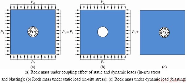
Figure 1 Concept for deep rock blasting:
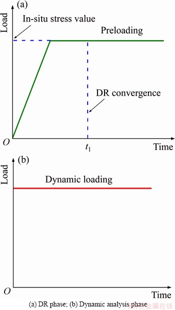
Figure 2 Two-phase loadings by using explicit DR method:
By this explicit DR method, generally, a two-step way is recommended for the whole dynamic numerical simulation of rock mass with in-situ stress, i.e., applying static loading for DR analysis and then performing dynamic analysis based on the DR analysis result. In the first step, the parameters for IDRFLG in the option of *CONTROL_DYNAMIC_RELAXATION and SIDR in the option of *DEFINE_CURVE need to be set to 1, and the termination time controlled in the option *CONTROL_TERMINATION needs to be set to 0. If the convergence criterion is satisfied, DR analysis stops and a DR result file (drdisp.sif) is generated. In the second step, dynamic analysis needs to be activated by setting the parameters of IDRFLG in *CONTROL_ DYNAMIC_RELAXATION option and SIDR in *DEFINE_ CURVE option to 2 and 0, respectively, and at the same time, the termination time should be set to the required one for dynamic analysis. As an alternative, it is also feasible to perform explicit DR and dynamic analysis together by using one step. At this point, the parameters for IDRFLG in the option of *CONTROL_DYNAMIC_ RELAXATION and SIDR in the option of *DEFINE_CURVE are 2 and 0, respectively.
2.1.2 Implicit DR method
Similar to the explicit DR method, implicit DR method also adopts DR to achieve stress initialization, the only difference is that the implicit solving function (implicit solver) of LS-DYNA is activated instead of explicit solver during the DR phase. Generally speaking, this method is particularly suited to DR since the loads applied during DR are generally small and the response is linear [37].
When implicit DR method is used for stress initialization, an implicit analysis is first performed to obtain the prestressed state of model by setting the parameter for IDRFLG in *CONTROL_ DYNAMIC_RELAXATION option to 5, and a reasonable initial time step size should be specified in *CONTROL_IMPLICIT_GENERAL option. Unlike the explicit DR method, the termination time of implicit preloading needs to be set via the parameter for DTERM in the *CONTROL_ DYNAMIC_RELAXATION option. In the preloading phase, the model is loaded linearly using a ramp load curve by setting the parameter for SIDR in *DEFINE_CURVE option to 1. The ramp time t1 for preloading is generally equal to the value of DRTERM as shown in Figure 3. When the value of DRTERM (termination time) is reached, the implicit DR analysis terminates, and then the dynamic analysis can be activated by setting the parameter for IMFLAG in the option of *CONTROL_IMPLICIT_GENERAL to 0.

Figure 3 Ramp loading curve in implicit DR method
2.2 Implicit stress initialization
The implicit analysis capability of LS-DYNA specifically designed for the simulation of metal forming spring-back was first released in Version 950. After that, many additional implicit features, including new element formulations for linear and modal analysis, were enriched in Version 970 [38]. A prerequisite for running implicit solver is to use a double precision version of LS-DYNA and a machine with a sufficient amount of memory.
There are totally three methods for stress initialization by using LS-DYNA implicit solution function, namely, dynain file method (two separate step analyses for the whole dynamic numerical simulation of rock mass with in-situ stress), implicit to explicit switch method (one-step analysis) and implicit DR method (mentioned previously in Section 2.1.2). Implicit analysis in LS-DYNA can be invoked via the command *CONTROL_ IMPLICIT_GENERAL. In addition, considering the powerful implicit solution performance of ANSYS software, the implicit-explicit sequence method using ANSYS/LS-DYNA will also be introduced in this section.
2.2.1 Dynain file method
When the input file (keyword file) for subsequent dynamic analysis needs to be greatly modified, dynain file method is more suitable [33]. This method uses LS-DYNA implicit solution function to achieve stress initialization and finish the whole numerical simulation through two separate analyses.
A dynain file can be generated by invoking the *INTERFACE_SPRINGBACK_LSDYNA option when the implicit solution is finished [38]. This dynain file contains the data describing the stress and strain of model. However, the dynain file does not include contact force and nodal velocity. Thus these variables from the preload analysis are not carried over to the subsequent analysis. In the subsequent dynamic analysis, by adding *INCLUDE command and the corresponding dynain file name into the keyword file, the program automatically imports dynain file as the basis of dynamic analysis.
2.2.2 Implicit to explicit switch method
Implicit to explicit switch method is generally used when the result file obtained from preloading analysis does not need to be significantly modified for subsequent dynamic analysis [34]. The switch between implicit analysis and explicit analysis is controlled by a step function curve as shown in Figure 4, in which the x-coordinate of curve represents the analysis time and the y-coordinate represents the solution method (1.0 for implicit and 0.0 for explicit). This method can be activated by setting the parameter for IMFLAG in the option of *CONTROL_IMPLICIT_GENERAL to -|curve ID|. In addition, the options of *CONTROL_ IMPLICIT_AUTO, *CONTROL_IMPLICIT_ SOLUTION, *CONTROL_IMPLICIT_SOLVER and *CONTROL_IMPLICIT_DYNAMICS also need to be set accordingly and the details can be referred to Ref. [32].
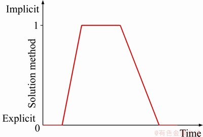
Figure 4 Implicit to explicit switch method
2.2.3 Implicit-explicit sequence method using ANSYS/LS-DYNA
At present, it is well known that explicit solution is efficient for dealing with dynamics problems, but for static problems, it is obviously not effective as the implicit solution method. Therefore, for the stress initialization and the following dynamic calculation, it is an excellent way to respectively take advantage of the implicit and explicit solution functions of ANSYS and LS-DYNA [40].
Unlike the explicit-implicit sequence solution in ANSYS, which is only limited to the simulation for metal forming process, implicit-explicit sequence solution has a wide application for engineering problems in which the prestressed state of material affects its dynamic response behavior [41]. An advantage of ANSYS pre-processing is that it is convenient to perform implicit-explicit conversion due to the easy transition of elements from ANSYS to LS-DYNA. The implicit solution in ANSYS can be subdivided into three steps. Firstly, the pressure (in-situ stress) is applied at the nodes of the model boundaries, and then an implicit analysis is performed. After that, the stress and the strain of element are obtained, which can be used to describe the stress state for the model under in-situ stress.
In this method, through the transmission of file, the stress initialization result obtained by implicit analysis in ANSYS is input into the explicit analysis in LS-DYNA. The data such as displacement and stress from the implicit solution in ANSYS are automatically written into the ANSYS/LS-DYNA DR file (drelax). The loadings of static stress and dynamic disturbance in ANSYS/ LS-DYNA are shown in Figure 5. A flow chart (as shown in Figure 6) presents the detailed implementation process.
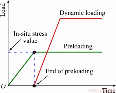
Figure 5 Loadings of static stress and dynamic disturbance
2.3 Transient stress initialization with mass damping
When it is difficult to converge for stress initialization by using the above two types of methods, a method named transient stress initialization with mass damping can be considered [34]. In this method, a modal analysis should be first performed to obtain the minimum circular frequency of system in LS-DYNA. Then, a ramp loading curve is applied to the model as shown in Figure 7(a), and the value of loading curve keeps constant after time t1. Theoretically, the solution time t1 should be bigger than the maximum period Tmax corresponding to the minimum circular frequency. Meanwhile, a critical damping is also applied to the model at the time t1 through the option of *DAMPING_GLOBAL. This critical damping is time-dependent and is controlled by a curve defined in the option of *DEFINE_CURVE. The critical damping is applied and then keeps constant, and it needs to be unloaded to zero when the dynamic load is applied at time t2 as shown in Figures 7(b) and (c).
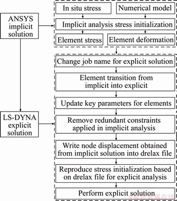
Figure 6 Procedures of implicit-explicit sequence solution in ANSYS/LS-DYNA
2.4 Quasi-static loading method
The energy generated by the external force acted on the model is mainly converted into kinetic and internal energies. At a very low speed, the kinetic energy can be negligible compared to the internal energy. Therefore, when using this method for stress initialization, the preloading time should be relatively long to minimize the inertial force and the kinetic energy and avoid interfering the subsequent dynamic analysis [42]. Precise prestressed results can be obtained by slowly applying a load in the form of a half-sine curve followed by a constant value (as shown in Figure 8) through the option of *DEFINE_CURVE in the explicit analysis. In general, in order to obtain a better stress initialization result, the preloading time should be bigger than t1. If the in-situ stress is induced by body force (gravity) or distributed pressure in engineering, it can be preloaded via *LOAD_BODY_OPTION or *LOAD_SEGMENT_ OPTION option.
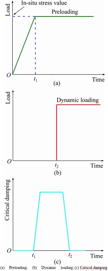
Figure 7 Transient stress initialization with mass damping:
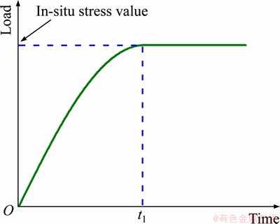
Figure 8 Half-sine loading curve
Furthermore, this method is usually used by combining with the restart function of LS-DYNA. The stress initialization is first performed and the corresponding result is saved in a “restart” file. This is the first run and the “restart” file will be invoked in the subsequent restart dynamic analysis (using r=restart file command). The history variables of nodes and elements including displacement and stress are stored in a binary file (runrsf or d3dump). In the restart run, the model is first mapped with the stored history variables to providing the preloaded stress state. The model in restart run could be the same one as in the first run (simple restart) or modified one (full restart). For a full restart run, the option of *STRESS_INITIALIZATION needs to be added in the second keyword file.
3 Case analysis with different methods
3.1 Numerical model
For case study, a plane model of 2.0 m×2.0 m with a 100 mm diameter hole in center (x=y=0) as shown in Figure 9 is used to simulate the blasting of rock mass with in-situ stress based on different stress initialization methods. There are a total of 40240 elements with dimensions of 10 mm×10 mm. Statistically, when the buried depth is over 1000 m, the lateral pressure coefficient k (k=P1/P2) ranges from 0.5 to 1.5 [43]. In current simulations, the value of k is set to 0.8 and the in-situ stress at a depth of 1000 m in x and y directions are P1=21.28 MPa, P2=26.6 MPa, respectively.
For simplicity, the pressure-time history curve of blasting (as shown in Figure 10) based on Blair’s model [44] is applied to the central holewall for explosion simulation. The pressure-time history is described by a pressure-decay function in the form of
 (1)
(1)
where PVN is the (von Neumann) borehole pressure at the detonation front produced by the explosive; H(t) is the Heaviside unit step function; n is an integer; γ is a pressure decay parameter; the values of n and γ are 3 and 0.7, respectively [30, 44-46].
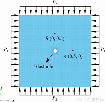
Figure 9 Configuration of numerical model and target points
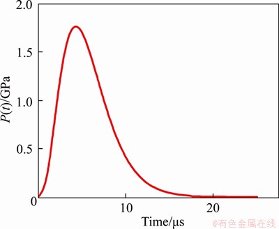
Figure 10 Pressure-time history of blasting
The Riedel-Hiermaier-Thoma (RHT) model proposed by RIEDEL et al [47] is first chosen to simulate the response of rock under the combined action of in-situ stress and blasting. This material model can be used to capture the dynamic mechanical performance of material under the influences of confining pressure, strain rate, strain hardening and damage softening [48]. The rock material parameters were determined by XIE et al [3] based on the experimental data obtained by DEHGAAN BANADAKI [49]. The detailed RHT material parameters for rock mass are listed in Table 1. Besides, to compare the stress initialization results with different rock constitutive models, the kinematic hardening plasticity model (MAT_ PLASTIC_KINEMATIC) which considers the effects of strain rate, strengthening and failure, is subsequently adopted [50-52]. The detailed material parameters of kinematic hardening plastic model for rock mass are listed in Table 2.
3.2 Simulation results
The seven methods introduced above for stress initialization are not all supported by only one of the material models suitable for simulating rock dynamic response behavior. For example, when the implicit solver is invoked in LS-DYNA, the RHT constitutive model is invalid, thus the implicit to explicit switch method and transient stress initialization with mass damping method (both of which are one-step methods for stress initialization and dynamic calculation) cannot be used for this rock material model. In addition, it should be noted here that in most of the preloading analyses, for speeding up the calculation and obtaining an accurate prestressed result, elastic material model is usually first adopted instead of the corresponding nonlinear rock material model in implicit analysis, and then the nonlinear rock material model is used in the subsequent explicit dynamic calculation by inheriting the stress result from the foregoing implicit solution. Therefore, in the current case study, only four methods (most popular methods) are selected as examples and employed to conduct the case analyses, including explicit DR method, implicit-explicit sequence method, dynain file method and quasi-static loading method (hereinafter, referred to as Explicit DR, Sequence, Dynain and Quasi-static, respectively).
Table 1 RHT material parameters for rock mass [3]
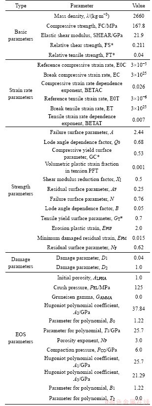
Table 2 Parameters of kinematic hardening plastic material for rock mass
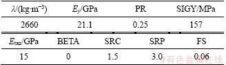
Figure 11 shows the stress states in RHT model after inheriting the stress initialization results from static solution with different methods. As can be seen, the stress initialization results obtained by using Sequence and Dynain methods are much lower than the preloading values (in-situ stress values). To compare the difference of mechanical response of rock mass under the combined action of in-situ stress and blasting based on different stress initialization methods, two target points A (0.5, 0) and B (0, 0.5) as shown in Figure 9 are specified to record the x- and y-stress-time histories during blasting, respectively, and the history curves are shown in Figure 12. It can be seen from the figures that when Explicit DR and Quasi-static are adopted, the x- and y-stress in the early parts of curves are basically concordant with the in-situ stress values, this indicates that before dynamic disturbance, accurate initial stress in rock mass was preloaded. Under the dynamic disturbance, the stress variations in the latter parts are also consistent. However, when the Sequence and Dynain methods are used, the initial stresses in the early parts of curves are obviously lower than expected (21.28 and 26.6 MPa, respectively), and under the dynamic disturbance, significant differences with the curves obtained based on the other two methods appear in the subsequent stress variations. Furthermore, through additional study, it is found that the similar phenomena can also be observed when some other rock material models, such as MAT_CONCRETE_DAMAGE_REL3 and MAT_JOHNSON_ HOLMQUIST_CONCRETE, are used. According to the above analysis, it can be concluded that more accurate dynamic numerical simulation of rock mass with in-situ stress by using RHT constitutive model can be performed based on the Explicit DR and Quasi-static methods.
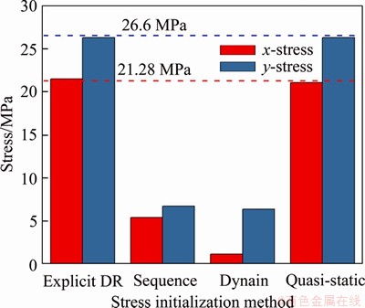
Figure 11 Stress initialization results with different methods using RHT constitutive model
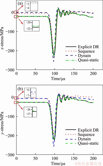
Figure 12 Stress-time history curves during blasting obtained from different stress initialization methods with RHT constitutive model
To compare the numerical results obtained from the above four stress initialization methods with different rock constitutive models, in the following, the kinematic hardening plasticity rock model as mentioned above is used for simulating rock blasting after inheriting the stress initialization results. Figure 13 shows the stress states in hardening plasticity rock model based on different stress initialization methods. At this time, it can be clearly observed from the picture that the stresses in the X- and Y-direction are all approximately concordant with the in-situ stress value. This indicates that the initial stress state obtained based on Sequence or Dynain methods is closely related to the selected rock material model.
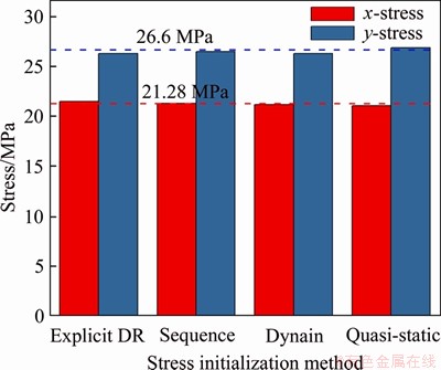
Figure 13 Stress initialization results with different methods using plastic hardening material model
Figures 14 and 15 show the contours of X- and Y-stress initialization in the model after preloading calculations using the above four methods, respectively. It can be seen that all the stresses in the rock mass except the surrounding area of borehole approximately equal to the stress applied on the model and similar stress concentration patterns with a small difference around the borehole are resulted, which implies that similar results for stress initialization can be obtained when these methods are employed.
To show the numerical damage of rock mass after blasting, the erosion algorithm with failure criteria (*MAT_ADD_EROSION) needs to be added. In the present modelling, the criteria of maximum principal strain εmax=0.06 and the critical tensile stress ft=8.41 MPa are both applied. It can be seen that the final damage distribution and range in rock mass under the combined action of in-situ stress and blasting are similar as shown in Figure 16. This also reflects that accurate preloading state can be obtained by using these four stress initialization methods.
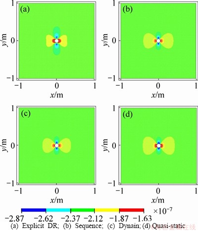
Figure 14 x-Stress initialization results with different methods:
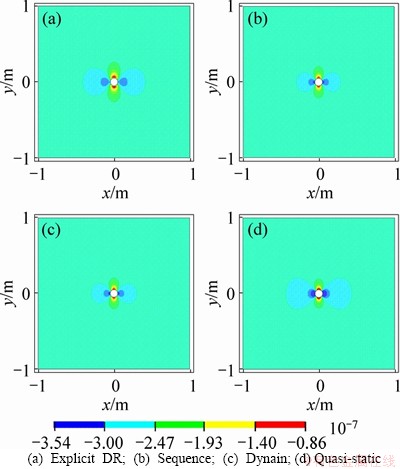
Figure 15 y-stress initialization results with different methods:
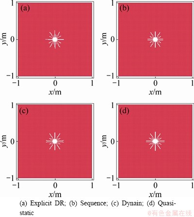
Figure 16 Damage distribution in rock mass under combined action of in-situ stress and blasting:
4 Discussion
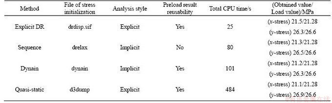
Based on the above case analysis, it can be found that the initial stress states obtained with different methods in kinematic hardening plasticity rock material model are basically the same with the in-situ stress condition. The simulations were run in a computer which has 2.9 GHz processor and 8 GB RAM with a 64-bit Windows 7 operating system. In order to evaluate the practicality of these four stress initialization methods, the information including computational efficiency, accuracy and advantages for each method are listed and compared in Table 3.
It is worth noting that similarly, the processes of preloading and dynamic loading in these four methods are all separated. In the simulation, the preloading analysis is performed first, and then the stress initialization result is taken as the basis for the dynamic analysis. Since some rock material models are not supported by the implicit solver, the parameters for rock material model and corresponding calculation settings can be modified before starting the subsequent dynamic analysis through separating the whole numerical simulation of rock under the combined action of in-situ stress and dynamic disturbance into two parts. It can be found from Table 3 that the Explicit DR method has an obvious advantage in calculation time over the other three methods. In addition, there is no strict restriction on which method should be used in numerical simulation, sometimes, it is very convenient to take advantage of the restart function (corresponding to the Quasi-static method) to achieve stress initialization.
5 Conclusions
Seven stress initialization methods currently available for reproducing steady in-situ stress state in model before performing dynamic numerical analysis in LS-DYNA were introduced. The most commonly used four methods, i.e., Explicit DR method, Sequence method, Dynain method and Quasi-static method, were exemplified through a case analysis for simulating rock blasting under in-situ stress condition. The stress initialization results obtained with different methods in RHT model and kinematic hardening plasticity rock material models were compared. Based on the simulations with the kinematic hardening plasticity model, the accuracy, solution time and applicability of these methods were also compared. The corresponding conclusions are listed as follows:
Table 3 Comparison of different stress initialization methods using kinematic hardening plasticity rock model
1) The stress initialization results obtained by using Sequence and Dynain methods are closely related to the selected rock material model, while they are not affected when the Explicit DR and Quasi-static methods are used.
2) Compared to the RHT model, the accuracy of stress initialization results obtained by different methods in kinematic hardening plasticity model are significantly different, and all of them meet the requirement for the simulation of rock blasting under in-situ stress condition, and the Explicit DR method has an obvious advantage in solution time.
3) It is recommended to use two separate analyses for the whole numerical simulation of rock mass under the combined action of in-situ stress and dynamic disturbance since the input file (keyword file) used for subsequent dynamic analysis can be easily modified.
Contributors
The overarching research goals were developed by LIU Ke-wei, YANG Jia-cai and LIU Zhi-xiang. LI Xu-dong and YANG Jia-cai analyzed the calculated results. The initial draft of the manuscript was written by YANG Jia-cai. All authors replied to reviewers’comments and revised the final version.
Conflict of interest
YANG Jia-cai, LIU Ke-wei, LI Xu-dong and LIU Zhi-xiang declare that they have no conflict of interest.
References
[1] LI Xi-bing, ZHOU Jian, WANG Shao-feng, LIU Bing. Review and practice of deep mining for solid mineral resources [J]. Chinese Journal of Nonferrous Metals, 2017, 27(6): 1236-1262. DOI: 10.19476/j.ysxb.1004.0609.2017. 06.021. (in Chinese)
[2] WANG Shao-feng, SUN Li-cheng, HUANG Lin-qi, LI Xi-bing, SHI Ying, YAO Jin-rui, DU Shao-lun. Non-explosive mining and waste utilization for achieving green mining in underground hard rock mine in China [J]. Transactions of Nonferrous Metals Society of China, 2019, 29(9): 1526-1533. DOI: 10.1016/s1003-6326(19)65099-5.
[3] XIE L X, LU W B, ZHANG Q B, JIANG Q H, CHEN M, ZHAO J. Analysis of damage mechanisms and optimization of cut blasting design under high in-situ stresses [J]. Tunnelling and Underground Space Technology, 2017, 66: 19-33. DOI: 10.1016/j.tust.2017.03.009.
[4] LIU Ke-wei, LI Xiao-han, LI Xi-bing, YAO Zhi-hua, SHU Zong-xian, YUAN Ming-hua. Characteristics and mechanisms of strain waves generated in rock by cylindrical explosive charges [J]. Journal of Central South University, 2016, 23: 2951-2957. DOI: 10.1007/s11771-016-3359-7.
[5] LIU Ke-wei, HAO Hong, LI Xi-bing. Numerical analysis of the stability of abandoned cavities in bench blasting [J]. International Journal of Rock Mechanics and Mining Sciences, 2017, 92: 30-39. DOI: 10.1016/j.ijrmms.2016. 12.008.
[6] LIU Ke-wei, YANG Jia-cai, LI Xi-bing, HAO Hong, LI Qi-yue, LIU Zhi-xiang, WANG Chun-yi. Study on the long-hole raising technique using one blast based on vertical crater retreat multiple deck shots [J]. International Journal of Rock Mechanics and Mining Sciences, 2018, 109: 52-67. DOI: 10.1016/j.ijrmms.2018.06.020.
[7] LIU Ke-wei, LI Xu-dong, HAO Hong, LI Xi-bing, SHA Yan-yan, WANG Wei-hua, LIU Xi-ling. Study on the raising technique using one blast based on the combination of long-hole presplitting and vertical crater retreat multiple- deck shots [J]. International Journal of Rock Mechanics and Mining Sciences, 2019, 113: 41-58. DOI: 10.1016/j.ijrmms. 2018.11.012.
[8] PENG Shu-quan, WANG Fan, LI Xi-bing, FAN Lin, GONG Feng-qiang. A microbial method for improving salt swelling behavior of sulfate saline soil by an experimental study [J]. Alexandria Engineering Journal, 2019, 58(4): 1353-1366. DOI: 10.1016/j.aej.2019.11.006
[9] CARTER J P, BOOKER J R. Sudden excavation of a long circular tunnel in elastic ground [J]. International Journal of Rock Mechanics and Mining ences & Geomechanics Abstracts, 1990, 27(2): 129-132. DOI: 10.1016/0148- 9062(89)91329-6.
[10] LI Xi-bing, CAO Wen-zhuo, ZHOU Zi-long, ZHOU yang. Influence of stress path on excavation unloading response [J]. Tunnelling and Underground Space Technology, 2014, 42: 237-246. DOI: 10.1016/j.tust.2014.03.002.
[11] ZHU W C, WEI J, ZHAO J, NIU L L. 2D numerical simulation on excavation damaged zone induced by dynamic stress redistribution [J]. Tunnelling and Underground Space Technology Incorporating Trenchless Technology Research, 2014, 43: 315-326. DOI: 10.1016/j.tust.2014.05.023.
[12] YANG J H, JIANG Q H, ZHANG Q B, ZHAO J. Dynamic stress adjustment and rock damage during blasting excavation in a deep-buried circular tunnel [J]. Tunnelling and Underground Space Technology, 2018, 71: 591-604. DOI: 10.1016/j.tust.2017.10.010.
[13] GONG Feng-qiang, LUO Yong, LI Xi-bing, SI Xue-feng, TAO Ming. Experimental simulation investigation on rockburst induced by spalling failure in deep circular tunnels [J]. Tunnelling and Underground Space Technology, 2018, 81: 413-427. DOI: 10.1016/j.tust.2018.07.035.
[14] GONG Feng-qiang, SI Xue-feng, LI Xi-bing, WANG Shan-yong. Experimental investigation of strain rockburst in circular caverns under deep three-dimensional high-stress conditions [J]. Rock Mechanics and Rock Engineering, 2018, 52(4): 1459-1474. DOI: 10.1007/s00603-018-1660-5.
[15] SI Xue-feng, GONG Feng-qiang. Strength-weakening effect and shear-tension failure mode transformation mechanism of rockburst for fine-grained granite under triaxial unloading compression [J]. International Journal of Rock Mechanics and Mining Sciences, 2020, 131: 104347. DOI: 10.1016/ j.ijrmms.2020.104347.
[16] DU Kun, TAO Ming, LI Xi-bing, ZHOU Jian. Experimental study of slabbing and rockburst induced by true-triaxial unloading and local dynamic disturbance [J]. Rock Mechanics and Rock Engineering, 2016, 49(9): 3437-3453. DOI: 10.1007/s00603-016-0990-4.
[17] FAN Y, LU W B, YAN P, CHEN M, ZHANG Y Z. Transient characters of energy changes induced by blasting excavation of deep-buried tunnels [J]. Tunnelling and Underground Space Technology, 2015, 49: 9-17. DOI: 10.1016/j.tust.2015. 04.003.
[18] LU Wen-bo, YANG Jian-hua, PENG Yan, CHEN Ming, ZHOU Chuang-bing, LUO Yi, JIN Li. Dynamic response of rock mass induced by the transient release of in-situ stress [J]. International Journal of Rock Mechanics and Mining Sciences, 2012, 53: 129-141. DOI: 10.1016/j.ijrmms.2012. 05.001.
[19] JU Yang, REN Zhang-yu, ZHENG Jiang-tao, GAO Feng, MING Ling-tao, CHIANG Fu-pen, XIE He-ping. Quantitative visualization methods for continuous evolution of three-dimensional discontinuous structures and stress field in subsurface rock mass induced by excavation and construction―An overview [J]. Engineering Geology, 2020, 265: 1-14. DOI: 10.1016/j.enggeo.2019.105443.
[20] SAMAR S A, YANN G, VINCENT R, MARWAN A. Initialization of highly heterogeneous virgin stress fields within the numerical modeling of large-scale mines [J]. International Journal of Rock Mechanics and Mining Sciences, 2017, 99: 50-62. DOI: 10.1016/j.ijrmms.2016.04.006.
[21] DAI Ru-lin, LI Zhong-fang, WANG Jiao. Research on initial geo-stress balance method based on ABAQUS [J]. Journal of Chongqing Technology and Business University(Natural Science Edition), 2012, 29(9): 76-81. DOI: 10.3969/j.issn. 1672-058X.2012.09.016. (in Chinese)
[22] LI Yong, GUO Yun-hua, ZHU Wei-shen, LI Shu-cai, ZHOU Hao. A modied initial in-situ stress inversion method based on FLAC3D with an engineering application [J]. Open Geosciences, 2015, 7(1): 824-835.
[23] LIU Jun-guang, CHEN Qin-fa, YIN Ting-chang. Velocity-stress boundary method to generate initial stress field of deep engineering in mine based on FLAC3D [J]. Metal Mine, 2018, 3: 26-31. DOI: 10.19614/j.cnki.jsks. 201803005. (in Chinese)
[24] YUAN Wei, SU Xue-bin, WANG Wei, WEN Lei, CHANG Jiang-fang. Numerical study of the contributions of shock wave and detonation gas to crack generation in deep rock without free surfaces [J]. Journal of Petroleum Science & Engineering, 2019, 177: 699-710. DOI: 10.1016/j.petrol. 2019.02.004.
[25] TIAN Li, LI Yong-xin. Analysis of damage effects of a prestressed reinforced concrete hollow beam subjected to the synergistic effects of blast and fragments [J]. Journal of Central South University (Science and Technology), 2019, 50(5): 1154-1164. DOI: 10.11817/j.issn.1672-7207.2019. 05.019. (in Chinese)
[26] JIANG Hua, CHORZEPA M G. An effective numerical simulation methodology to predict the impact response of pre-stressed concrete members [J]. Engineering Failure Analysis, 2015, 55: 63-78. DOI: 10.1016/j.engfailanal.2015. 05.006.
[27] CHEN Yi-yi, ZHANG Da-zhao, XUE Wei-chen, LU Wen-sheng. Seismic performance of prestressed concrete stand structure supporting retractable steel roof [J]. Frontiers of Architecture & Civil Engineering in China, 2009, 3(2): 117-124. DOI: 10.1007/s11709-009-0024-3.
[28] DONG Jian-hua, ZHU Yan-peng, YONG Zhou, MA Wei. Dynamic calculation model and seismic response for frame supporting structure with prestressed anchors [J]. Science China Technological Sciences, 2010, 53(7): 1957-1966. DOI: 10.1007/s11431-010-3241-z.
[29] WU Jian-hua, HAO Ding-di, LI Wen-sheng, REN Xiao-dan. Numerical modeling and simulation of a prestressed concrete containment vessel [J]. Annals of Nuclear Energy, 2018, 21: 269-283. DOI: 10.1016/j.anucene.2018.06.039.
[30] YI Chang-ping, JOHANSSON D, GREBERG J. Effects of in-situ stresses on the fracturing of rock by blasting [J]. Computers and Geotechnics, 2018, 104: 321-330. DOI: 10.1016/j.compgeo.2017.12.004.
[31] LI Xi-bing, GONG Feng-qiang, TAO Ming, DONG Long-jun, DU Kun, MA Chun-de, ZHOU Zi-long, YIN Tu-bing. Failure mechanism and coupled static-dynamic loading theory in deep hard rock mining: A review [J]. Journal of Rock Mechanics and Geotechnical Engineering, 2017, 9(4): 767-782. DOI: 10.1016/j.jrmge.2017.04.004.
[32] LS-DYNA. Keyword user’s manual Volume I, Ver. 971 [M]. Livermore: Livermore Software Technology Corporation (LSCT), 2012.
[33] BARNES M. Form finding and analysis of tension structures by dynamic relaxation [J]. International Journal of Space Structures, 1999, 14(2): 89-104. DOI: 10.1260/02663519 91494722.
[34] BING Dao. Stress initialization in LS-DYNA [EB/OL]. 2016-07-23. http://www.jishulink.com/content/post/284766. (in Chinese)
[35] STREETER M, RHODE-BARBARIGOS L, ADRIAENSSENS S. Form finding and analysis of inflatable dams using dynamic relaxation [J]. Applied Mathematics & Computation, 2015, 267: 742-749. DOI: 10.1016/j.amc. 2014.12.054.
[36] ZHAO Hua-tao, TAO Ming, LI Xi-bing, CAO Wen-zhuo, WU Cheng-qing. Estimation of spalling strength of sandstone under different pre-confining pressure by experiment and numerical simulation [J]. International Journal of Impact Engineering, 2019, 133: 1-11. DOI: 10.1016/j.ijimpeng.2019.103359.https://www.dynasupport.com/howtos/implicit/implicit-dynamic-relaxation.
[37] LS-DYNA Support. Implicit: Dynamic relaxation [EB/OL]. https://www.dynasupport.com/howtos/implicit/implicit-dynamic-relaxation.
[38] HALLQUIST J O. LS-DYNA Theory Manual [M]. California: Livermore Software Technology Corporation.
[39] JANG Rui-bin. The method of auto panel springback compensation based on dynain [J]. Mechanical & Electrical Engineering Technology, 2009, 38(6): 95-97. DOI: 10.3969/ j.issn.1009-9492.2009.06.031. (in Chinese)
[40] ANSYS documentation. Version 12.1, ANSYS LS-DYNA user’s guide [M]. Beijing, China: ANSYS Inc., 2009.
[41] WENG Lei, LI Xi-bing, TAO Ming. Influence of geostress orientation on fracture response of deep underground cavity subjected to dynamic loading [J]. Shock and Vibration, 20151: 575879. DOI: 10.1155/2015/575879.
[42] CUI Jian, HAO Hong, SHI Yan-chao. Study of concrete damage mechanism under hydrostatic pressure by numerical simulations [J]. Construction & Building Materials, 2018, 160: 440-449. DOI: 10.1016/j.conbuildmat.2017.11.083.
[43] LI Xin-ping, WANG Bin, ZHOU Gui-long. Research on distribution rule of geostress in deep stratum in chinese mainland [J]. Chinese Journal of Rock Mechanics and Engineering, 2012, 31(z1): 2875-2880. DOI: 10.3969/j.issn. 1000-6915.2012.z1.036. (in Chinese)
[44] BLAIR D P. A comparison of Heelan and exact solutions for seismic radiation from a short cylindrical charge [J]. Geophysics, 2007, 72(2): 33-41. DOI: 10.1190/ 1.2424543.
[45] YI Chang-ping, JOHANSSON D, ULF N, BEYGLOU A. Stress wave interaction between two adjacent blast holes [J]. Rock Mechanics & Rock Engineering, 2016, 49(5): 1803-1812. DOI: 10.1007/s00603-015-0876-x.
[46] YILMAZ O, UNLU T. Three dimensional numerical rock damage analysis under blasting load [J]. Tunnelling and Underground Space, 2013, 38: 266-278. DOI: 10.1016/ j.tust.2013.07.007.
[47] RIEDEL W, KAWAI N, KONDO K I. Numerical assessment for impact strength measurements in concrete materials [J]. International Journal of Impact Engineering, 2009, 36(2): 283-293. DOI: 10.1016/j.ijimpeng.2007.12.012.
[48] BORRVALL T. The RHT concrete model in LS-DYNA [C]// 8th European LS-DYNA Conference. 2011.
[49] DEHGHAN BANADAKI M M, MOHANTY B. Numerical simulation of stress wave induced fractures in rock [J]. International Journal of Impact Engineering, 2012, 40-41: 16-25. DOI: 10.1016/j.ijimpeng.2011.08.010.
[50] ZHAO Jian-jian, ZHANG Yong, RANJITH P G. Numerical simulation of blasting-induced fracture expansion in coal masses [J]. International Journal of Rock Mechanics and Mining Sciences, 2017, 100: 28-39. DOI: 10.1016/ j.ijrmms.2017.10.015.
[51] HU Tao, LI Xiang-long, GUAN Si, HE Li-hua. Numerical simulation of blasting effect with divided charge structures [J]. Engineering, 2014, 12(6): 39-45. DOI: 10.3969/j.issn. 1009-1742.2014.11.005.
[52] WANG Fang-tian, TU Shi-hao, YUAN Yong, FENG Yu-feng, CHEN Fang, TU Hong-sheng. Deep-hole pre-split blasting mechanism and its application for controlled roof caving in shallow depth seams [J]. International Journal of Rock Mechanics and Mining Sciences, 2013, 64: 112-121. DOI: 10.1016/j.ijrmms.2013.08.026.
(Edited by HE Yun-bin)
中文导读
高地应力岩体动态数值模拟中的应力初始化方法研究
摘要:在深部岩体工程中,岩体在动态扰动作用下的响应行为与其自身的原位地应力状态密切相关,因此,岩体应力初始化作为高地应力岩体动态响应数值模拟的第一步,其作用至关重要。首先,介绍了基于LS-DYNA的应力初始化方法,包括模拟中再现稳定原位应力状态的基本原理及其相应的操作步骤。其后,通过实例分析,以RHT和塑性硬化岩石材料模型为基础,采用四种常用的应力初始化方法(即显式动态松弛法、隐-显式序列法、Dynain文件法和准静态方法)模拟高地应力条件下的岩体爆破响应。通过模拟对比得出,以隐-显式序列法和Dynain文件法获得的应力初始化结果与所选用的岩石材料模型密切相关,而在求解时间方面,显式动态松弛法较其他方法具有明显优势。此外,在原位应力和动态扰动共同作用下的岩体响应模拟过程中,为便于实际操作,建议采取两步骤相继独立分析(地应力分析和动态分析)的方式开展数值模拟工作。
关键词:原位应力;应力初始化方法;动态扰动;数值模拟;岩体
Foundation item: Project(41630642) supported by the Key Project of National Natural Science Foundation of China; Project(51974360) supported by the National Natural Science Foundation of China; Project(2018JJ3656) supported by the Natural Science Foundation of Hunan Province, China
Received date: 2020-06-30; Accepted date: 2020-09-17
Corresponding author: LIU Ke-wei, PhD, Associate Professor; Tel: +86-18229726328; E-mail: kewei_liu@csu.edu.cn; ORCID: https:// orcid.org/0000-0003-4686-5336

