Trans. Nonferrous Met. Soc. China 22(2012) s302-s308
Pre-bulging effect during sheet hydroforming process of aluminum alloy box with unequal height and flat bottom
LANG Li-hui1, WANG Yong-ming1, XIE Ya-su1, YANG Xi-ying1, XU Ying-qiang2
1. School of Mechanical Engineering and Automation, Beihang University, Beijing 100191, China;
2. Sheet Metal Factory, Shanghai Aircraft Manufacturing Corporation, Shanghai 200436, China
Received 28 August 2012; accepted 25 October 2012
Abstract: Pre-bulging effect on the sheet hydroforming process of irregular box with unequal height and flat bottom was investigated by means of numerical simulation and experiment. The influences of pre-bulging height and pre-bulging pressure on the forming were discussed respectively. The pressure loading path was optimized. The results show that pre-bulging has important influences on the forming results. Too high pre-bulging height causes the crack and obvious crease at the punch nose near the lowest corner. Too low pre-bulging height causes fracture at the punch nose of the highest corner. Pre-bulging pressure has a smaller effect on the fracture at the punch nose of the highest corner when the pre-bulging height is reasonable. But over high pre-bulging pressure causes crack and obvious crease at the punch nose near the lowest corner. Failure can be avoided by using reasonable pre-bulging height and pre-bulging pressure.
Key words: aluminum alloy; sheet hydroforming; pre-bulging; irregular box
1 Introduction
Hydromechanical deep drawing (HDD) technology, illustrated in Fig. 1, is one type of sheet hydroforming, which belongs to the flexible forming. Fluid medium is used in a die cavity as the female die when forming a hollow shell part. The shape of the work-piece is determined mainly by the shape of the punch, the die cavity replacing the conventional female die, which is also indicated as the passive sheet hydroforming [1-3]. When the punch goes down into the die cavity, the blank is drawn into the die cavity filled with oil or other liquids. The liquid in the die cavity will be pressurized and will push the blank tightly onto the punch surface. Then, the effect of friction retention is at work. At the same time, the liquid in the die cavity will flow out from the gap between the die and the blank, therefore, fluid lubrication that will reduce frictional force is produced. The limit drawing ratio (LDR) value of sheet metal can be increased and the surface quality and the dimensional accuracy of the part can be upgraded. By using this process, some complicated structures and poor- formability materials can be formed such as aluminum alloys in the aircraft industry [4-6]. But it is still a new forming process in aircraft manufacturing industries, the forming mechanism of the HDD process has not been made sufficiently clear, so some bottleneck points and key technologies must be solved and discussed firstly [7,8].
The aluminum alloy box with unequal height and flat bottom is one non-axial symmetry part emerged normally in the field of aircraft industry. Due to its complex geometric shape, the stress and strain distribution is extremely non-uniform in deforming area. The fluid pressure acting on blank makes the deformation more complex. Because of the low plasticity and formability of aluminum alloy, it is easier to crack in the HDD process.
Many process parameters influence the HDD process, such as die cavity pressure, blank holder force and pre-bulging. But the most important one is the pre-bulging. The pre-bulging deformation is extraordinarily uneven in the HDD process of aluminum alloy box with unequal height and flat bottom, and it influences the final deformation results significantly.
Pre-bulging means that at the primary stage of sheet hydroforming, one pre-bulging unit is used to increase the pressure in the die cavity actively, meanwhile, the punch is fixed at a certain position. The blank will be formed into a certain shape under the constraint of the mold. When the pre-bulging pressure reaches the pre-setting value, the punch will go down. Generally, pre-bulging has two effects: the first one is to build the pressure at the beginning stage of hydroforming process; the second one is to change the stress and strain states of sheet around the punch nose and the die entrance radius to avoid the defects of fracture and wrinkling at the beginning of forming.
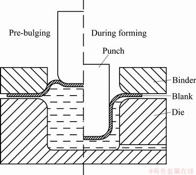
Fig. 1 Schematic drawing of hydromechanical deep drawing process
The pre-bulging method has two parameters including pre-bulging height (Hpre) and pre-bulging pressure. For box with unequal height and flat bottom, pre-bulging height is the distance between punch pre-bugling position and punch low limit position along the punch moving direction, as shown in Fig. 2.

Fig. 2 Pre-bulging height in HDD process of box with unequal height and flat bottom
The influence of pre-bulging on HDD process has been studied previously and mainly focused on the axisymmetric parts. LANG et al [9-11] studied the pre-bulging effect on the cylindrical cup hydroforming by simulation and experiment. LIU et al [12] discussed the effects of initial inverse bulging pressure on the hydrodynamic deep drawing process of aluminum alloy cylindrical cups with a hemispherical bottom. CHEN et al [13] studied the influence of pre-bulging on deformation and hardness of dual-phase steel cylindrical cup by hydrodynamic deep drawing process.
However, the influence of pre-bulging on the complicated parts HDD process has not been studied thoroughly. Especially, few investigations have been done with respect to the pre-bulging effect on the HDD process of irregular components in aircraft manufacturing industries. Because of the complicated geometry, the mechanism of pre-bulging improving formability and restraining rupture should be further studied so that some conclusions could be obtained and can be applied to forming other irregular components in aircraft. So, in this work, one typical irregular box in aircraft with unequal height and flat bottom was selected as research object, aimed at the failure modes in the HDD process of this part, the influence of pre-bulging on the forming will be investigated by numerical simulation and experiment.
2 Basic conditions
2.1 Needed part
The shape and dimension of the part investigated in this work are shown in Fig. 3. It can be seen that the side wall height of the part is extremely unequal. The side wall height in corner D is 105.5 mm, which is the maximum, and the height in corner B is 54.5 mm, which is the minimum. It is the typical representative of many complicated components in aircraft by using the lightweight materials such as the aluminum alloys.

Fig. 3 Shape and dimension of typical aircraft part
2.2 Material
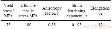
The material used was a 2.03 mm-thick aluminum alloy 2024-O. The property of this material is illustrated in Table 1. It can be seen that this material has a poor cold formability. The dimension of blank used in simulation and experiment is d460 mm.
2.3 Numerical analysis model
In the experiment, the tools are closed during the forming process and cannot be observed directly. Only the final results can be obtained. The stress distribution and the failure occurrence cannot be caught in time, so sometimes a wrong decision will be caused. Nowadays, it has been reported by many papers that the numerical simulation is a powerful tool for analyzing the forming process [14-16]. Numerical simulation technology can simulate the forming process, predict the defect and provide various deforming information. Also, it can reduce experiment times and cost of research, shorten the research period. This paper adopts commercial explicit software Dynaform5.6.
Table 1 Material performance parameters of sheet 2024-O
In simulation, all tools were modeled using a rigid element with a four-node shell. The blank was modeled using the four-node quadrilateral, Belytschko-Lin-Tsay element with five integration points through the shell thickness. Penalty contact interfaces were used to enforce the intermittent contact and sliding boundary condition. A friction coefficient μ=0.1 was used for the interface between the blank and the punch, and μ=0.05 for the blank and the other tools, which was found that the simulated results by using these parameters meet the final results from the experiment. The fixed gap method in the HDD was used and the gap between die and binder is a constant 2.2 mm.
2.4 Equipment and tool set-up
All experiments were carried out on a 550 t double-action sheet hydroforming press that was studied and developed in Beihang University, in which the variable blank holding force and the non-uniform pressure can be realized. The punch speed is adjustable from 5 to 15 mm/s. The pre-bulging function can be realized in this system and the maximum pre-bulging pressure can reach 100 MPa and the maximum pressure in the die cavity can increase to 150 MPa.
3 Experimental results
3.1 Failure modes
In order to investigate the effect of pre-bulging height and pre-bulging pressure, two group experiments were carried out. In experiment, there are two types of failure mode: the fracture at the punch nose of the corner D (Failure 1) as shown in Fig. 4(a); the crack and obvious crease at the punch nose near the corner B (Failure 2) as shown in Fig. 4(b).
The first group experiments were implemented with different pre-bulging heights under the same pressure loading curve, pre-bulging pressure was 2 MPa and the maximum die cavity pressure was 15 MPa, and the results are listed in Table 2. The second group experiments were implemented with different pre-bulging pressures at the same pre-bulging height of 90 mm, and the results are listed in Table 3.

Fig. 4 Failure types
Table 2 Experiment results with different pre-bulging heights
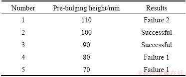
Table 3 Experiment results at different pre-bulging pressures

It was found that the pre-bulging has a significant effect on the final results and virtual simulation will give great help to find the effect of the pre-bulging.
3.2 Wall thickness distribution
Figure 5 shows the perfect part obtained in experiment when the pre-bulging height is 90 mm and pre-bulging pressure is 2 MPa. Figure 6(a) shows the wall thickness distribution at the corner D. Fig. 6(b) shows the wall thickness distribution at the corner B. It can be seen that the wall thickness is the minimum at the punch nose in corner D. The reason for this is that the deep drawing depth is the largest at the corner D. Also, it can be seen that the simulation results agree well with that of experiments. So the numerical simulation analysis model built in this work is credible.

Fig. 5 Formed perfect part in experiment

Fig. 6 Wall thickness distribution at corner D (a) and corner B (b)
4 Numerical simulation analysis
4.1 Contrast between CDD and HDD
Figure 7 shows the cross section of finite element model from the highest point to the lowest point. From Fig.7 (a), it can be seen that, because of the unequal side wall height, the punch contacts firstly the highest blank located at the corner D in conventional deep drawing process. The contact area is very small, and most of the blanks do not contact with punch. The tensile stress will be very high in the local contact area. As a result, the blank will become thin excessively in the local contact area.

Fig. 7 Contrast between CDD and HDD in preliminary forming stage
In the preliminary stage of HDD process, the pre-bulging makes the blank inverse drawing, as shown in Fig. 7(b). The blanks located at lower side cling to punch earlier. Local contact between blank and punch could be avoided. The deformation and the deep drawing force are more uniform. It is also helpful to make the materials have more uniform deformation in the following deep drawing process. Pre-bulging includes two parameters: pre-bulging height and pre-bulging pressure, which will be analyzed respectively.
4.2 Effect of pre-bulging height
The experiments No.1-5 which have a different pre-bulging height were simulated. The numerical simulation results of the maximum wall thickness thinning ratio with different pre-bulging heights are illustrated in Fig. 8. From the numerical simulation results, it can be found that the key parameter of pre-bulging height has a clear process window and a suitable parameter has to be selected.
Figure 9 shows the numerical simulation forming limitation diagram when the pre-bulging height was 70 mm. There was no pressure acting on the blank in the preliminary stage of HDD process. As stated above, the highest sheet blanks contact with punch in local area, so the sheet metal becomes thin excessively, and the fracture occurs around the punch nose at the initial time of forming, as shown in Fig. 4(a).

Fig. 8 Simulation results of maximum thickness reduction ratio with different pre-bulging heights
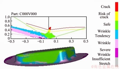
Fig. 9 Forming limitation diagram in numerical simulation
Figure 10 shows the pre-bulging results of simulation when pre-bulging height was 110 mm. In the pre-bulging stage, the punch does not move into the die cavity. When the punch goes down by 45 mm, the blank shape is shown in Fig. 10(a). It can be found that because of the unequal sidewall height, there are too many sheet metal blanks stored at the lower corner B. When the punch goes down a certain distance, the blanks at corner D can be drawn in die successfully, while there are still too many blanks in corner B. The blanks in the punch nose area are pushed into the clearance between the punch and the blank holder, as shown in Fig. 10(b), which will cause a too heavy bending and unbending effect and induce a very large local plasticity strain. Finally, the sheet will crack in this area, as shown in Fig. 4(b). There is an obvious crease, which causes this part to be scraped.
Figure 11 shows the pre-bulging simulation results when the pre-bulging height was 90 mm. It can be seen that the punch has moved into the die cavity a certain depth at the highest corner D in the pre-bulging stage, but not at the lowest corner B. There are appropriate amount of sheet metal blanks stored at the lower corner B in pre-bulging stage. When the punch goes down by 25 mm subsequently, the blanks at corner B are subjected to reasonable bending and unbending. As described above, the reasonable bending and unbending will harden the sheet around the punch nose considerably, then the fracture at the punch nose of the corner D is prevented. At the same time, the crack and obvious crease at the punch nose near the corner B are also avoided.

Fig. 10 Blank shape with pre-bulging height of 110 mm

Fig. 11 Blank shape with pre-bulging height of 90 mm
From the above discussion, it can be concluded that too high or too low pre-bulging height is not helpful for the forming. If pre-bulging height is too high, it will cause crack and obvious crease at the punch nose near the corner B. If pre-bulging height is too low, it will cause fracture at the punch nose of the corner D. The punch moving into the die cavity a little distance in corner D will be helpful for the forming process in pre-bulging stage. The reasonable pre-bulging height is 90-100 mm.
4.3 Effect of pre-bulging pressure
In order to study the effects of pre-bulging pressure, experiments No. 6-10 were simulated with pre-bulging height of 90 mm. The maximum thickness reduction ratio is illustrated in Fig. 12. It can be concluded that the effect of pre-bulging pressure is similar to that of pre-bulging height, too high or too low pressure is not helpful for the control of wall thickness reduction. In the preliminary stage of HDD process, the blank has not covered the punch fully. If the pre-bulging pressure is too high, the blank will be bulged into large size, so the thickness becomes thin seriously. If the pre-bulging pressure is too low, the friction retention and fluid lubrication effect cannot act in HDD process, so the thickness will also become thin seriously. But on the whole, the variation of the maximum wall thickness reduction ratio is small. So the pre-bulging pressure has a smaller effect on the Failure 1 when the pre-bulging height is reasonable.
The simulation results with pre-bulging pressure of 2 MPa and 5 MPa are shown in Fig. 13. It can be seen that there are more sheet metals stored at corner B under pre-bulging pressure of 5 MPa. As described above, the sheet blank is subjected to a heavy bending and unbending, which will cause Failure 2. So the reasonable pre-bulging pressure is 1-3 MPa.

Fig. 12 Simulation results of maximum thickness reduction ratio under different pre-bulging pressures

Fig. 13 Numerical simulation results under different pre-bulging pressures
5 Conclusions
1) Aluminum box with unequal height and flat bottom is formed in one step with the HDD process by the fixed gap method. The thickness distribution result of numerical simulation is in a good agreement with the experiment.
2) If pre-bulging height is too high, it will cause crack and obvious crease at the punch nose near the lowest corner B. On the contrary, if pre-bulging height is too low, it will cause fracture at the punch nose of the highest corner D. The punch moving into the die cavity a little distance in corner D will be helpful for the hydroforming process in pre-bulging stage.
3) The pre-bulging pressure has a smaller effect on the fracture at the punch nose of the highest corner D when the pre-bulging height is reasonable. But the too high pre-bulging pressure will cause crack and obvious crease at the punch nose near the lowest corner B.
4) In order to avoid defects, the reasonable pre-bulging height is 90-100 mm and the reasonable pre-bulging pressure is 1-3 MPa.
References
[1] SIEGERT K, HAUSSERMANN M, LOSCH B, RIEGER R. Recent development in hydroforming technology [J]. Journal of Materials Processing Technology, 2000, 98(2): 251-258.
[2] GELIN J C, GHOUATI O, PAQUIER P. Modelling and control of hydroforming processes for flanges forming [J]. CIRP Annals-Manufacturing Technology, 1998, 47 (1): 213-216.
[3] LANG L H, WANG Z R, KANG D C, YUAN S J, ZHANG S H, DANCKERT J, NIELSEN K B. Hydroforming highlights: Sheet hydroforming and tube hydroforming [J]. Journal of Materials Processing Technology, 2004, 151 (1): 165-177.
[4] ZHANG S H. Developments in hydroforming [J]. Journal of Materials Processing Technology, 1999, 91(1): 236-244.
[5] XU Yong-chao, KANG Da-chang. Hydromechanical deep drawing of alumite LF6 [J]. The Chinese Journal of Nonferrous Metals, 2003, 13(1): 60-64. (in Chinese)
[6] NAKAGAWA T, NAKAMURA K, AMINO H. Various applications of hydraulic counter pressure deep drawing [J]. Journal of Materials Processing Technology, 1997, 71: 160-167.
[7] LANG L H, LI T, AN D Y, CHI C L, NIELSEN K B, DANCKERT J. Investigation into hydromechanical deep drawing of aluminum alloy-complicated components in aircraft manufacturing [J]. Materials Science and Engineering A, 2009, 499: 320-324.
[8] LI Tao, LANG Li-hui, AN Dong-yang. Investigation into the hydroforming process and quality controlling of complicated aircraft aluminum part [J]. China Mechanical Engineering, 2006, 17(S1): 8-11. (in Chinese)
[9] LANG L H, NIELSEN K B, DANCKERT J. Investigation into the effect of pre-bulging during hydromechanical deep drawing with uniform pressure onto the blank [J]. International Journal of Machine Tools and Manufacture, 2004, 44 (6): 649-657.
[10] LANG L H, LI T, ZHOU X B, DANCKERT J, NIELSEN K B. The effect of the key process parameters in the innovative hydroforming on the formed parts [J]. Journal of Materials Processing Technology, 2007, 187-188: 304-308.
[11] LANG L H, DANCKERT J, NIELSEN K B. Investigation into hydrodynamic deep drawing assisted by radial pressure part I. Experimental observations of the forming process of aluminum alloy [J]. Journal of Materials Processing Technology, 2004, 148(1): 119-131.
[12] LIU Xiao-jing, XU Yong-chao, YUAN Shi-jian. The influence of inverse bulging pressure on the hydrodynamic deep drawing process of aluminium alloy cylindrical cups with a hemispherical bottom [J]. Journal of Plasticity Engineering, 2008, 15(3): 42-46. (in Chinese)
[13] CHEN Bao-guo, XU Yong-chao. Influence of pre-bulging on deformation and hardness of dual-phase steel cylindrical cup by hydrodynamic deep drawing process [J]. Materials Science and Technology, 2011, 19(1): 17-20. (in Chinese)
[14] LANG L H, DANCKERT J, NIELSEN K B, KANG D C, ZHANG S H. Key technologies of numerical simulation of cup hydrodynamic deep drawing [J]. Transactions of Nonferrous Metals Society of China, 2003, (6): 772-776.
[15] KIM T J, YANG D Y, HAN S S. Numerical modeling of the multi-stage sheet pair hydroforming process [J]. Journal of Materials Processing Technology, 2004, 151(1-3): 48-53.
[16] ZAMPALONI M, ABEDRABBO N, POURBOGHRAT F. Experimental and numerical study of stamp hydroforming of sheet metals [J]. Journal of Materials Processing Technology, 2003, 45(11): 1815-1848.
铝合金不等高盒形件充液成形过程预胀形效应
郎利辉1,王永铭1,谢亚苏1,杨希英1,徐应强2
1. 北京航空航天大学 机械工程及自动化学院,北京 100191;
2. 上海飞机制造有限公司 钣金厂,上海 200436
摘 要:利用数值模拟和实验方法研究预胀形对不等高平底异形盒形件充液成形过程的影响,探讨预胀高度和预胀压力对成形结果的影响规律,优化压力加载路径。结果表明:预胀形对成形结果影响较大。过高的预胀高度会导致不等高盒形件最低拐角区凸模圆角处的裂纹和折痕,过低的预胀高度会导致最高拐角区凸模圆角处的破裂。当预胀高度在合理范围时,预胀压力对筒壁最高拐角区凸模圆角处的破裂影响较小。但是,过大的预胀压力会导致筒壁最低拐角区凸模圆角附近产生裂纹及褶皱。合理预胀高度和预胀压力可有效控制失效形式的发生。
关键词:铝合金;板材充液成形;预胀形;异形盒形件
(Edited by HE Yun-bin)
Foundation item: Project (2010-T02) supported by the State Key Laboratory of Materials Processing and Mould Technology, China; Project (2010DFA52030) supported by the China International Science and Technology Cooperation
Corresponding author: LANG Li-hui; Tel/Fax: +86-10-82316821; E-mail: lang@buaa.edu.cn
DOI: 10.1016/S1003-6326(12)61723-3

