Trans. Nonferrous Met. Soc. China 27(2017) 1759-1766
Microstructures and properties of Cu/Ag(Invar) composites fabricated by powder metallurgy
Xin ZHANG1, Dan WU2, Lei YANG3, Chang-dong SHI3, Yu-cheng WU4, Wen-ming TANG1,4
1. School of Materials Science and Engineering, Hefei University of Technology, Hefei 230009, China;
2. Jiangsu Fasten Group Co., Ltd., Jiangyin 214433, China;
3. 43 Institute, China Electronics Technology Group Corporation, Hefei 230088, China;
4. Key Laboratory of Functional Materials and Devices of Anhui Province, Hefei University of Technology, Hefei 230009, China
Received 6 May 2016; accepted 30 August 2016
Abstract: The Ag (Invar) composite powder prepared by ball milling was used to fabricate the Cu/Ag (Invar) composites. Microstructures and properties of the composites were studied after sintering and thermo-mechanical treatment. The results indicate that during ball milling, micro-forging weld and work-hardening fracture result in that the average particle size of the Ag (Invar) powder increases rapidly at first, and then decreases sharply, finally tends to be constant. Compared with the Cu/Invar ones, the sinterability of the composites is greatly improved, resulting in that the pores in them are smaller in amount and size. After the thermo-mechanical treatment, the Cu/Ag (Invar) composites are nearly fully dense with the optimum phase composition and element distribution. More importantly, Cu and the Invar alloy in the composites distribute continuously in a three-dimensional (3D) network structure. Cu/Invar interface diffusion is effectively inhibited by the Ag barrier layer, leading to a great improvement of the mechanical and thermal properties of the Cu/Ag (Invar) composites.
Key words: Cu/Invar composite; Ag barrier layer; sintering; thermo-mechanical treatment; 3D network structure; mechanical properties; thermal properties
1 Introduction
The wide use of high-density, multi-functional and large-power electronic devices demands competent electronic packaging materials of high thermal conductivity (TC), mechanical strength and formability and machinability, low coefficient of thermal expansion (CTE) and etc [1-4]. The Cu/Invar composites are considered as one kind of novel electronic packaging materials because they combine high TC of Cu with low CTE (<2×10⁻⁶ K-1) and high strength of the Invar alloys (Fe-36Ni alloy) [5-7]. Moreover, the composites also have a good formability and machinability because they are the metal-reinforced composites without high-volume ceramic reinforcements such as SiC and Si. However, during preparing the Cu/Invar composites through powder metallurgy, property degradation of the composites, e.g., the increase in thermal expansion coefficient of the Invar alloys and the decrease in thermal conductivity of Cu, take place, because the impurity atoms are introduced into the Cu and Invar alloy through a rapid Cu/Invar interfacial diffusion during sintering the Cu/Invar composites [8]. Therefore, the improvement of the microstructures and properties of the Cu/Invar composites depends on the method to effectively inhibit the Cu/Invar interfacial diffusion. It is believed that lowering the sintering temperature and setting the interface diffusion barrier can solve these tough problems wholly or partly.
As shown in the Ag-Cu and Ag-Fe phase diagrams [9], almost no atom inter-diffusion takes place across the Ag/Invar interface and Ag also has a much low solid solubility in Cu, the Ag atoms dissolved in Cu may precipitate as the Ag rods during the thermo-mechanical treatment process. Strength and electrical conductivity of the Cu alloy therefore increase. Moreover, the melting point of Ag is the lowest, compared with those of Cu and the Invar alloy (they are 960.5, 1083 and 1430 °C, respectively), therefore, the Ag layer at the Cu/Invar interface can lower the sintering temperature and prohibit the Cu/Invar interface diffusion of the PMed Cu/Invar composites [10,11]. The sinterability, mechanical and physical properties of the composites are therefore increased.
In our previous studies, fully-dense Cu/Invar composites with 60% (mass fraction) Invar alloy were prepared in terms of a powder metallurgy and thermo-mechanical treatment technique [12]. The composites are of high tensile strength (360 MPa) and low CTE (10.8×10⁻⁶ K-1), but their thermal conductivity is not high enough (about 50 W/(m・K), though it is three times higher than that of the Invar alloy (15 W/(m・K))). In this work, the Ag (Invar) composite powder was prepared via a new technique by ball-milling the mixture of Ag and Invar alloy powder. And then, the Ag(Invar) powder was used to fabricate the Cu/Ag(Invar) composites via the same technique as Ref. [12]. Differences in microstructure and property between the Cu/Invar and Cu/Ag (Invar) composites were identified. The effects of the Ag layer on the Cu/Invar interface diffusion and the sintering properties of the Cu/Ag (Invar) composites were also investigated.
2 Experimental
2.1 Materials
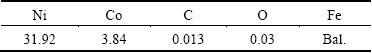
Electrolytic Cu powder (99.9% purity and particle size <50 μm) and Ag powder (99.9% purity and particle size <30 μm) were provided by Zhongjinyan New Materials Co., Ltd., Beijing, China. Gas-atomized Invar alloy powder with particle <70 μm size was provided by Tianjiu Metal Materials Co., Ltd., Changsha, China. The composition of the Invar alloy powder is listed in Table 1.
Table 1 Chemical composition of Invar alloy (mass fraction, %)
2.2 Processing
2.2.1 Ag(Invar) composite powder
The Invar alloy and Ag powders were first blended in a mass ratio of 9:1. Ball milling of the blended powder was carried out using a QM-3SP2 type planetary mill operated at a speed of 360 r/min. The corundum vial and balls were employed during the ball milling process with a ball-to-powder mass ratio of 15:1. The dehydrated alcohol was used as the milling medium in order to avoid excessive weld of the Ag(Invar) powder. After milling for 50 h, the Ag(Invar) composite powder was dried at 80 °C and then annealed at 600 °C for 2 h to eliminate the residual stress.
2.2.2 Cu/Invar and Cu/Ag(Invar) composites
The Cu powder and the Invar or Ag(Invar) powder were weighed in a mass ratio of 40:60. After adding 0.5% zinc stearate as lubricant, the blended powder was mixed for 10 h using a two-roller mixer. The mixed powder was uniaxially compacted using a 769YP-40C type powder compressing machine with a forming pressure of 400 MPa and a dwelling time of 2 min. The Cu/Invar preforms were sintered at 1000 °C for 60 min using an OTF-1200X type furnace at a heating rate of 5 °C/min. After sintering, the Cu/Invar samples were cooled at a rate of 5 °C/min from the sintering temperature to 800 °C and then were cooled with furnace. The whole sintering process was protected in a high-purity H2 atmosphere with a gas flow rate of 100 mL/min. The Cu/Ag(Invar) preforms were sintered at 800 °C for 60 min and a heating/cooling rate of 5 °C/min, and then were cooled with furnace from 600 °C to room temperature. The sintered Cu/Invar and Cu/Ag(Invar) composites were multi-pass cold-rolled using a LG500 type cold mill with two 9Cr2Mo rollers of a size of d180 mm × 400 mm. The rolling force was set to 500 kN to implement about 5% deformation reduction for each pass. When the cold-rolling process was done, the Cu/Invar and the Cu/Ag(Invar) composite specimens were annealed at 750 °C for 2 h and 450 °C for 2 h, respectively.
2.3 Measurement and characterization
The morphologies of the Ag(Invar) composite powders milled for different time were observed using a SM6490 type scanning electron microscope (SEM). The average particle size of the powder was tested by a Mastersizer 2000 type laser particle size analyzer. The as-sintered and the as-rolled specimens were etched in an aqua regia solution with a volume ratio of the concentrated hydrochloric acid to nitric acid of 3:1. Microstructures of the composite specimens were observed using a MR5000 type optical microscope (OM) and SEM. Phases of the composite powders were analyzed using a D/MAX-2500V type X-ray diffractometer (XRD) of the Cu Kα radiation. The filament voltage and current were set at 40 kV and 40 mA, respectively. The samples were scanned at 2θ values from 10° to 90° at a rate of 2 (°)/min.
The Archimedes principle was employed to measure the density of the composites. Tensile properties of the composites were measured using a CMT5105 type microcomputer control electron universal testing machine with a stretching rate of 0.5 mm/min. According to GB/T228-2010, the rectangular specimens with cross-sectional dimensions of 8 mm × 2 mm were employed. The CTEs of the composite specimens with dimensions of 50 mm × 8 mm × 3 mm were tested using a PCY-III type CTE tester in the temperature range from 20 to 250 °C at a heating rate of 3 °C/min. Room- temperature electrical conductivities of the composite specimens with dimensions of 50 mm × 8 mm × 5 mm were measured using an Agilent U3606A type desktop multimeter. Before testing, two silver wires were fastened on each terminal of the specimen. The contact points were then filled with the silver conductive adhesive to ensure that the silver wires contacted with the specimen tightly. After the specimens were heated under an infrared lamp until the conductive adhesive was completely solidified, the electrical conductivities of them were tested. And thus, the TCs of the composite specimens were then deduced, according to the Wiedemann-Franz law [12].
3 Results and discussion
3.1 Preparation of Ag (Invar) composite powder
In Fig. 1(a), large grey spherical particles are the Invar alloy particles, while small bright particles are the Ag ones. Most of the Ag particles adhere on the surface of the Invar alloy particles; however, small amount of them are aggregated. Because the Invar alloy and Ag are both ductile metals, the Ag(Invar) composite powder has a high plastic deformation capacity [13]. In the initial stage of ball milling, the Ag and Invar alloy powders are laminated via the micro-forging process. Small Ag flakes are welded on the large Invar alloy sheets (Fig. 1(b)). Subsequently, the composite powder is refined, owing to the work hardening fracture (Fig. 1(c)). Finally, the micro-forging weld and the work hardening fracture are in equilibrium, the morphology and size of the milled composite powder are not changed any more (Fig. 1(d)).
As shown in Fig. 2, the average particle size of the Ag (Invar) powder decreases rapidly with the increase of milling time, but tends to be a constant after the powder is milled for 30 h and longer. It is about 8 μm after the powder milled for 50 h, indicating that a balance between micro-forging weld and work-hardening fracture has been established at the time.

Fig. 1 SEM morphologies of Ag(Invar) composite powders milled for different time

Fig. 2 Average particle size of Ag(Invar) composite powder vs milling time
3.2 Microstructures
As shown in Fig. 3(a), Cu (white) and the Invar alloy (grey) distribute uniformly in the Cu/Invar composites sintered at 1000 °C, however, the relative density of the composites is only 85.2%. There are lots of pores in the composites, especially in the Invar alloy and/or at poor Cu/Invar alloy interface (Fig. 3(a)), mainly resulting from the low sinterability of the Invar alloy powder and/or the low Cu/Invar interface wettability. As the rolling reduction of the composite increases to 55%, both Cu and the Invar alloy have apparent plastic deformations. Cu distributes semi- continuously in a three-dimensional network structure. The pores are partly cold-welded, and thus the relative density of the composite is rapidly increased to more than 95% (Fig. 3(b)). As for the Cu/Ag(Invar) composites sintered at 800 °C, both Cu and the Invar alloy distribute uniformly, and the pores in them are small in size and amount. The relative density of the composites is as high as 94.1%, indicating that the composites have a higher sinterability than the Cu/Invar composites (Fig. 3(c)). The explanations are as follows: 1) the Ag flakes on the Invar alloy particles can effectively improve the sinterability of the Invar alloy so that most of the pores in the Invar alloy are eliminated; 2) the Ag flakes at the Cu/Invar interface can improve the interfacial wettability and decrease the interface porosity. As the rolling reduction increases to 55%, the Cu/Ag(Invar) composites are of a relative density of 99.1% in which Cu and the Invar alloy distribute in the continuous three-dimensional network structure (Fig. 3(d)).
3.3 Element distribution
As shown in Fig. 4(a), the α-Fe (Ni, Co) (111) diffraction peak located at 2θ=44°-45° was detected in the sintered Cu/Invar composite, except the Cu and Invar alloy ones. It is known that the crystal structure of the Fe-Ni(Co) alloy is sensitive to its Ni (Co) content. The Fe-Ni(Co) alloy tends to be a body-centered cubic (BCC) structure, as the Ni(Co) content is lower than 30% (mass fraction) [14]. During sintering the Cu/Invar composites, the Fe and Ni atoms in the Invar alloy diffuse into Cu to form the Cu (Fe, Ni) solid solution. The Cu diffraction peaks therefore shift about 0.15° right (large diffraction angle orientation), because the atomic radii of Fe (0.124 nm) and Ni (0.125 nm) are smaller than that of Cu (0.128 nm). As a result, the Ni content of the Invar alloy adjacent to the Cu/Invar interface decreases, which is likely lower than 30%. So, the crystal structure of the Invar alloy transforms from the face-centered cubic (FCC) to the BCC. As for the BCC Fe-Ni alloy (α-Fe (Ni, Co)), its Invar effect loses partly [15], and it has a high CTE accordingly.

Fig. 3 OM images showing microstructures of Cu/Invar and Cu/Ag(Invar) composites

Fig. 4 XRD patterns of sintered Cu/Invar (a) and Cu/Ag(Invar) (b) composites
As for the Cu/Ag(Invar) composites, the intensity of the α-Fe(Ni, Co) diffraction peaks is rather weak. The Cu diffraction peaks shift more left (Fig. 4(b)), which are nearly consistent with those of pure Cu, compared to Fig. 4(a). This indicates that almost no Fe or Ni atoms dissolve into Cu, and thus the Ag layer at the Cu/Invar interface can effectively inhibit the diffusion of Cu/Invar interface.
The difference in atom diffusion of the Cu/Invar and Cu/Ag(Invar) composites during sintering can be characterized by elemental line scanning analysis across the Cu/Invar and Cu/Ag(Invar) interfaces. As shown in Fig. 5(a), the slight grey area is Cu, and the dark grey area is the Invar alloy in the sintered Cu/Invar composites. During sintering, the Cu atoms diffuse into the Invar alloy obviously, almost through the whole Invar alloy region (Fig. 5(b)). Similarly, the Fe and Ni atoms diffuse from the Invar alloy into Cu, and the Ni content in the Invar alloy adjacent to the Cu/Invar interface decreases (Figs. 5(c) and (d)), resulting in the fact that the crystal structure of the Invar alloy transforms from FCC to BCC. And thus, a new phase of α-Fe (Ni, Co) is therefore formed.
After the composites were etched, the dark grey area in Fig. 6(a) is Cu, the light grey area is the Invar alloy, and the white area is Ag. Some of the Ag particles distribute along the Cu/Invar interface, the others are in the Invar alloy. After sintering and the thermo- mechanical treatment, most of Ag still aggregates at the Cu/Invar interface, the diffusion of the Ag atoms in the Invar alloy and Cu is limited (Fig. 6(b)). As a result, the interdiffusion of the Cu, Fe and Ni atoms across the Cu/Invar interface is prohibited by the Ag barrier layer (Figs. 6(c)-(e)). Unfortunately, no continuous Ag layer the Cu/Invar interface is achieved in this work. At the Cu/Invar interface without the Ag layer, the inter- diffusion of the Cu, Fe and Ni atoms still takes place. Apparently, whole wrap of the Invar alloy particles by the Ag layer is impossibly achieved via ball milling. In our next work, a new method should be employed to form a continuous Ag layer on the Invar alloy particles, which can prohibit or even prevent the interdiffusion of the Cu, Fe and Ni atoms across the Cu/Invar interface.
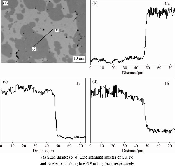
Fig. 5 Cross-sectional SEM image and elemental line scanning spectra across Cu/Invar interface in Cu/Invar composites after sintering

Fig. 6 Cross-sectional BSE SEM image and elemental line scanning spectra across Cu/Invar interface in Cu/Ag(Invar) composites after thermo-mechanical treatment
3.4 Properties
After the thermo-mechanical treatment, the relative density of the Cu/Ag(Invar) composites is slightly higher than that of the Cu/Invar composites. Meanwhile, the tensile strength and elastic modulus of the Cu/Ag(Invar) composites are two times higher than those of the latter. This is because firstly, strength of the powder metallurgy materials is highly sensitive to the porosity in them. The strength of the Cu/Ag(Invar) composites increases with increasing their density. Secondly, the Ag(Invar) composite powder prepared by ball milling is very fine. The Cu/Ag(Invar) composites are therefore reinforced via the grain refinement mechanism [7]. Finally, the dissolution and precipitation of the Ag atoms in Cu results in the solution strengthening and/or precipitation strengthening of the Cu matrix. It is recognized as the main reason to the improvement of the mechanical properties of the Cu/Ag (Invar) composites.
The CTEs of the two composites are nearly equal to each other; however, the TC of the Cu/Ag(Invar) composites is about 1.7 times larger than that of the Cu/Invar composites (Table 2). The low TC of the Cu/Invar composites mainly attributes to the serious Cu/Invar interface diffusion and low density [16, 17]. Moreover, the TC of Ag is higher than that of Cu (Ag: 429 W/(m・K) and Cu: 400 W/(m・K) in theory) and the dissolution of Ag in Cu can decrease the solid solubility of Fe in Cu [18]. They are also beneficial to the improvement of the TC of the Cu/Ag(Invar) composites. As mentioned above, the Cu/Invar interface diffusion in the Cu/Ag (Invar) composites is inhibited to some extent, the Invar effect of the Invar alloy is more maintained, which is beneficial to lowering the CTE of the Cu/Ag(Invar) composites. However, the Cu/Ag(Invar) composites have a higher relative density, and also the CTE of Ag in the composites is higher than that of Cu (Ag: 19.5×10⁻⁶ K-1 and Cu: 17.7×10⁻⁶ K-1), which results in the improvement of the CTE of the Cu/Ag(Invar) composites. So, the CTE of the Cu/Invar and that of the Cu/Ag (Invar) composites are approximately the same.
Table 2 Mechanical and physical properties of Cu/Invar and Cu/Ag (Invar) composites

4 Conclusions
1) During ball milling, the Ag(Invar) composite powder experiences three stages of laminating, micro-forging weld and work hardening fracture. At last, the balance between the micro-forging weld and the work hardening fracture is established. After the Ag (Invar) powder is milled for 50 h, its average particle size is about 8 μm.
2) Compared with the Cu/Invar composites, the Cu/Ag(Invar) composites have lower sintering temperature, higher density and smaller pores. When the rolling reduction reaches 55%, the Cu/Ag(Invar) composites have a relative density of 99.1%. Both Cu and the Invar alloy in the composites exist as continuous three-dimensional networks.
3) The Ag layer can effectively prohibit the Cu/Invar interface diffusion. The Fe and Ni contents in the Cu matrix and the Cu content in the Invar alloy both decrease, and α-Fe(Ni, Co) phase in the Cu/Ag(Invar) composites is effectively restrained.
4) After the thermo-mechanical treatment, though the density and CTE are nearly the same as those of the Cu/Invar composites, the Cu/Ag(Invar) composites have 2 times higher tensile strength and elastic modulus and 1.7 times higher TC compared with the Cu/Invar composites.
References
[1] JIA Qi-jin, LIUJun-you, LI Yan-xia, WANG Wen-shao. Microstructure and properties of electronic packaging box with high silicon aluminum-base alloy by semi-solid thixoforming [J]. Transactions of Nonferrous Metals Society of China, 2013, 23: 80-85.
[2] XIE H, TAN Q, LEE Y C. Encyclopedia of materials: Science and technology [M]. Oxford: Pergamon Press, 2001.
[3] MA Ru-long, PENG Chao-qun, WANG Ri-chu, ZHANG Chun, XIE Li-chuan. Research progress of diamond/aluminum composites for electronic packaging [J]. The Chinese Journal of Nonferrous Metals, 2014, 24: 689-699. (in Chinese)
[4] FANG Meng, HU Ling, YANG Lei, SHI Chang-dong, WU Yu-cheng, TANG Wen-ming. Electroless plating and growth kinetics of Ni-P alloy film on SiCp/Al composite with a high SiC volume fraction [J]. Transactions of Nonferrous Metals Society of China, 2016, 26: 799-805.
[5] RYELANDTA S, MERTENSB A, DELANNAY F. Al/stainless-invar composites with tailored anisotropy for thermal management in light weight electronic packaging [J]. Materials & Design, 2015, 85: 318-323.
[6] TAO Jing-mei, ZHU Xin-kun, TIAN Wei-wei, YANG Peng, YANG Hao. Properties and microstructure of Cu/diamond composites prepared by spark plasma sintering method [J]. Transactions of Nonferrous Metals Society of China, 2014, 24: 3210-3214.
[7] LI Li-bei, SUN Yu-fu. Physical properties of metallic materials [M]. Beijing: Metallurgical Industry Press, 2011. (in Chinese)
[8] WU Dan, WU Shi-pu, YANG Lei, SHI Chang-dong, WU Yu-cheng, TANG Wen-ming. Preparation of Cu/Invar composites by powder metallurgy [J]. Powder Metallurgy, 2015, 58: 100-105.
[9] DAI Yong-nian. Binary alloy phase diagrams [M]. Beijing: The Science Press, 2009. (in Chinese)
[10] GAO H Y, WANG J, SHU D, SUN B D. Effect of Ag on the microstructure and properties of Cu-Fe in situ composites [J]. Scripta Materialia, 2005, 53: 1105-1109.
[11] SONG J S, HONG S I, PARK Y G. Deformation processing and strength/conductivity properties of Cu-Fe-Ag microcomposites [J]. Journal of Alloys and Compounds, 2005, 388: 69-74.
[12] WU Dan, YANG Lei, SHI Chang-dong, WU Yu-cheng, TANG Wen-ming. Effects of rolling and annealing on microstructures and properties of Cu/Invar electronic packaging composites prepared by powder metallurgy [J]. Transactions of Nonferrous Metals Society of China, 2015, 25: 1995-2002.
[13] NAGARJUNA S. Thermal conductivity of Cu-4.5Ti alloy [J]. Bulletin of Materials Science, 2004, 27: 69-71.
[14] CHEN Zhen-hua, CHEN Ding. Mechanical alloying and solid-liquid reaction milling [M]. Beijing: Chemical industry Press, 2006. (in Chinese)
[15] ZHOU Y H, HARMELIN M,BIGOT J. Martensitic transformation in ultrafine Fe-Ni powders [J]. Materials Science and Engineering A, 1990, 124: 241-249.
[16] KONKOVA T, MIRONOV S, KORZNIKOV G, MYSHLYAEV M M, SEMIATIN S L. Effect of cryogenic temperature and change of strain path on grain refinement during rolling of Cu-30Zn brass [J]. Materials & Design, 2015, 86: 913-921.
[17] STOLK J, MANTHIRAM A. Chemical synthesis and properties of nanocrystalline Cu-Fe-Ni alloys [J]. Materials Science and Engineering A, 1999, 60: 112-117.
[18] JIANG Guo-sheng, WANG Zi-fa, ZHANG Ying-jiu, XU Zheng, LIU Fang, ZHAO Xiao-ming. Factors affecting DG alloys electrical resistivity [J]. The Chinese Journal of Nonferrous Metals, 1998, 8: 395-398. (in Chinese).
粉末冶金法制备Cu/Ag(Invar)复合材料的显微组织与性能
张 昕1,吴 丹2,杨 磊3,史常东3,吴玉程4,汤文明1, 4
1. 合肥工业大学 材料科学与工程学院,合肥230009;
2. 江苏法尔胜集团公司,江阴 214433;
3. 中国电子科技集团公司43研究所,合肥 230088;
4. 合肥工业大学 安徽省功能材料与器件重点实验室,合肥 230009
摘 要:采用球磨制得的Ag(Invar)复合粉体制备Cu/Ag(Invar)复合材料。研究烧结及形变热处理后复合材料的显微组织结构与性能。结果表明,在球磨过程中,微锻造焊合与加工硬化断裂共同作用导致Ag(Invar)粉体的平均颗粒尺寸先急剧增大,再快速降低,最后趋于稳定。相对于Cu/Invar复合材料,Cu/Ag(Invar)复合材料的烧结性能大大提高,其中的气孔小而少。形变热处理后,该复合材料近乎完全致密,具有最佳的相成分与元素分布,更重要的是,该复合材料中的Cu及Invar合金均呈三维网络状连续分布。Cu/Invar界面扩散被Ag阻挡层有效抑制,使Cu/Ag(Invar)复合材料的力学及热学性能均有明显提高。
关键词:Cu/Invar复合材料;Ag阻挡层;烧结;形变热处理;三维网状结构;力学性能;热学性能
(Edited by Wei-ping CHEN)
Foundation item: Project (2014DFA50860) supported by the International Science & Technology Cooperation Program of China
Corresponding author: Wen-ming TANG; Tel/Fax: +86-551-62901362; E-mail: wmtang@hfut.edu.cn
DOI: 10.1016/S1003-6326(17)60198-5

