
Influence of voids on interlaminar shear strength of carbon/epoxy fabric laminates
ZHU Hong-yan(�����)1, LI Di-hong(��غ�)1, ZHANG Dong-xing(�Ŷ���)1,
WU Bao-chang(�ⱦ��)2, CHEN Yu-yong(������)1
1. School of Materials Science and Engineering, Harbin Institute of Technology, Harbin 150001, China;
2. Harbin Aircraft Industry Co., Ltd., Harbin 150060, China
Received 10 June 2009; accepted 15 August 2009
Abstract: The effects of voids (void content, void shape and size) on the interlaminar shear strength of [(��45)4/(0,90)/(��45)2]S and [(��45)/04/(0,90)/02]S composite laminates were investigated. Specimens with void contents in the range of 0.2%-8.0% for [(��45)4/(0,90)/(��45)2]S and 0.2%-6.1% for [(��45)/04/(0,90)/02]S were fabricated from carbon/epoxy fabric through varying autoclave pressures. The characteristics of the voids were studied by using optical image analysis to explain the interlaminar shear strength results. The influences of voids on the interlaminar shear strength of the two stacking sequences were compared in terms of the void content and size and shape of the void. The effect of voids on the initiation and propagation of interlaminar failure of both stacking sequence composites was found.
Key words: carbon fibre reinforced polymer(CFRP) composite; void content; void size; void shape; interlaminar shears strength
1 Introduction
The effect of voids on the mechanical properties of carbon fiber reinforced composite structures has been widely researched[1-6]. There is general agreement that voids have a detrimental effect on the matrix dominated properties, such as interlaminar shear strength[7-10], compressive strength and modulus[11-12], and bending properties[13-16]. Although all these studies indicate that mechanical properties decrease with increasing void content, the magnitude of the void effect is different. The interlaminar shear strength(ILSS) of fabric CFRP specimens with different void contents can be taken as an instance. ILSS has been widely researched because of its high void sensitivity. For examples, COSTA et al[17] reported that the ILSS values decrease by about 34% for carbon/epoxy fabric laminates when the void content increases from 0.55% up to 5.60%, whereas JEONG[18] reported a reduction of 30% for graphite/epoxy laminates made from woven fabric prepreg when the void content increases from 0 to 12%.
The effect of voids on the mechanical properties of composite laminates is influenced by a large number of factors, such as voids shape, size and location. The mechanical properties as a function of void content of the same composite structure manufactured with the same manufacturing process can be different. This is because that the void content is a volume characteristic. Most published work researched the effect of voids on the mechanical behavior of composite laminates through quantifying voids by content (%). Recently, it was realized that this method is too simplistic. The void shape, size and location play an important role. WISNOM et al[19] studied the effect of void shape, size and distribution. They manufactured the samples with discrete and distributed voids in unidirectional CFRP by positioning the PTFE inserts. The result shows that the ILSS decreases by 20% as the void aspect ratio goes from 1 to 4. The void shape, size and location are important because they can influence whether or not a crack emanates from a void. COSTA et al[17] found that triangular voids and the cracks emanate from the triangular voids. So, to deeply understand the effect of voids on the mechanical properties of composite laminates, void shapes, sizes and locations must be taken into account.
The stacking sequences affect the void shape and size and in turn influence the effect of voids on the mechanical behavior of the composite laminates. Little work on the effect of voids on the ILSS property in the literature dealt with different stacking sequences. The purpose of this research is to compare the effects of voids on [(��45)4/(0,90)/(��45)2]S and [(��45)/04/(0,90)/02]S laminates, and to study the effect of void sizes and shapes on the ILSS. The same carbon/epoxy fabric is used in both laminates with the difference only in the stacking sequences. Samples with void content in the range of 0.2%-8.0% for [(��45)4/(0,90)/(��45)2]S and 0.2%-6.1% for [(��45)/04/(0,90)/02]S were produced. The void content was ultrasonically inspected and microscopic inspection was used to investigate the size and shape of voids. The interlaminar shear strength was studied.
2 Experimental
2.1 Fabrication of specimens
Two different stacking sequences were studied in this work: [(��45)4/(0,90)/(��45)2]S (sp4-01) and [(��45)/04/(0,90)/02]S (sp4-02) lay-ups. The composite laminates were fabricated using carbon fabric reinforced epoxy. T300 fibers were used for the laminates. The fiber content of the composite laminates was 58%-62%.
The laminates were produced using a vacuum bag and autoclave cure technique. The composite laminates with high porosity were manufactured using autoclave pressures of 0, 0.1 and 0.4 MPa. The vacuum was held during the curing process. All specimens were cured in an autoclave using the standard cure cycle recommended by manufactures.
Three rectangular plates of 300 mm��200 mm were fabricated as described above for each type of stacking sequence considered. All plates were inspected using an ultrasonic detector to evaluate the distribution of void content. Areas of uniform void content within each plate were identified, and mechanical test and image analysis specimens were cut from each of those areas.
Three different void content levels ranging from 0.2%-8.0% were obtained for [(��45)4/(0,90)/(��45)2]S. Also, three different void content levels ranging from 0.2%-6.1% were produced for [(��45)/04/(0,90)/02]S.
2.2 Microstructure analysis
The void contents, shapes and sizes of voids in the carbon/epoxy samples were measured by optical assessment according to a Chinese standard. For each stacking sequence, one specimen corresponds to an ILSS sample before testing. Five tested samples of each porosity level were analyzed, and image analysis was performed using a magnification. The sections of the specimens for image analysis were cut parallelly and perpendicularly, respectively, to the ply direction. The samples for image analysis were embedded in an epoxy resin and carefully polished using a polishing machine with 400, 600, 800 and 1 500 grit size silicon carbide abrasive paper. Then, the samples were finished with 1 ��m diamond paste. The samples were observed with an optical microscope (VNT-100). The images were analyzed through the image analysis software. A quantification of void content, void size and shape (aspect ratio) was acquired through this analysis.
2.3 Interlaminar shear strength tests(ILSS)
Interlaminar shear strength tests were conducted following the GB/T 3357��1982 (short beam shear test).
Ten specimens at each void content level were used to determine the interlaminar shear strength. The specimens with dimensions of 30 mm��6 mm��4 mm for [(��45)4/(0,90)/(��45)2]S and 25 mm��6 mm��3 mm for [(��45)/04/(0,90)/02]S (length��width��thickness) were tested to assess the effect of porosity on the interlaminar shear strength.
3 Results and discussion
3.1 Effect of cure pressures on void content and interlaminar shear strength
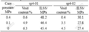
Table 1 lists the measurement of the void content and ILSS for different cure pressures. As can be seen, the ILSS decreases by 5.8% for the sp4-01 and 8.9% for the sp4-02 as the cure pressure goes from 0.4 MPa to 0.1 MPa.
Table 1 Measurement of void contents and strength for different cure pressures
3.2 Microstructure analysis
To assess the relationship between voids and interlaminar shear strength, a detailed study was undertaken to investigate the characteristic of voids in the laminates. Reference samples with void contents in the range of 0.2%-8.0% for [(��45)4/(0,90)/ (��45)2]S and 0.2%-6.1% for [(��45)/04/(0,90)/02]S were used for this purpose.
3.2.1 Location of voids
Fig.1 shows a typical photomicrograph of samples with different void contents before testing. In these figures, the voids in the sp4-01 laminates are preferentially located between the plies of the laminates and run along the direction parallelly to the plies. Most voids in the sp4-02 laminates are situated between the plies of the laminates. Some voids appear in the plies of the laminates, and the voids exhibit a spherical pattern. No voids grow in a direction perpendicular to the plies. Most large voids are observed to be in contact with fibers. Fig.1 indicates that voids grow to larger ones gradually with increasing void contents.
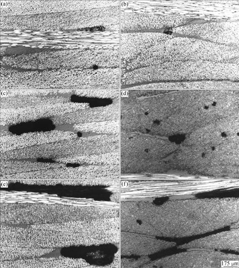
Fig.1 Micrographs of samples with different void contents before testing: (a) sp4-01(0.4%); (b) sp4-02(0.5%); (c) sp4-01(3.9%); (d) sp4-02(1.7%); (e) sp4-01(6.5%); (f) sp4-02(4.7%)
3.2.2 Void size and shape
To comprehensively evaluate the effect of voids on the ILSS, detailed analysis of the sizes, shapes of voids is necessary. Image analysis software was used to analyze the void shape, size, and the surface area of each captured void. Reference specimens with void contents in the range 0.2%-8.0% for the sp4-01 laminates and 0.2%-6.1% for the sp4-02 laminates were used for this purpose. An equivalent diameter, D, is defined as:
 (1)
(1)
where A is the measured area of the void.
Fig.2 shows the size distributions based on D. For sp4-01, D mainly distributes in the range of 3.3-248.7 ��m when the void content goes from 0.2% to 1.2% (Fig.2(a)) and 3.6-264.4 ��m in the range of 3.9%-5.0% (Fig.2(b)) and 3.5-277.1 ��m in the range of 6.5%-8.0% (Fig.2(c)). The average D values are 11.7, 34.1 and 37.6 ��m, respectively. The largest D is 248.7 ��m with the void content of 1.2% when the void content goes from 0.2% to 1.2%. For sp4-02, the void size mainly distributes in the range of 3.6-168.9 ��m when the void content goes from 0.2% to 0.8% (Fig.2(a)) and 3.6- 204.0 ��m in the range of 1.7%-2.7% (Fig.2 (b)) and 3.6- 297.6 ��m in the range of 4.7%-6.1% (Fig.2 (c)). The average D values are 11.0, 17.3 and 28.1 ��m, respectively. The largest D is 168.9 ��m with the void content of 0.8% when the void content goes from 0.2% to 0.8%.
As can be seen in Fig.2(a), the frequency of voids with D in the range of 3.6-50.0 ��m is dominant. As the void content increases, the proportion of larger voids becomes greater.
Fig.3 shows the aspect ratio variations as a function
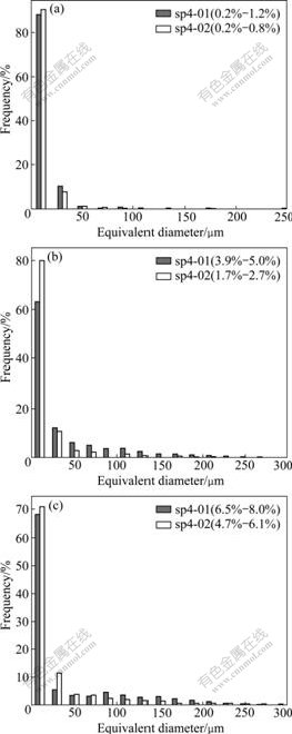
Fig.2 Void size distributions based on equivalent diameter with different void contents: (a) sp4-01(0.2%-1.2%), sp4-02 (0.2%-0.8%); (b) sp4-01(3.9%-5.0%), sp4-02(1.7%-2.7%); (c) sp4-01(6.5%-8.0%), sp4-02(4.7%-6.1%)
of equivalent diameter. The aspect ratio increases with increasing D. However, the aspect ratio is not the maximum when D is the maximum.
These findings are very important with regard to the use of microstructure analysis as a tool for assessing the effect of voids.
3.3 Effect of void contents on interlaminar shear strength(ILSS)
Fig.4 presents the interlaminar shear strength results for sp4-01 and sp4-02 laminates. As expected, the interlaminar shear strength values of sp4-01 and sp4-02 are both very sensitive to void contents. However, the dropoff rate is different. As reported in Fig.4, there is a decrease of 11% in ILSS when the void content goes from 0.2% to 8.0% for sp4-01, and each 1% increase in void content decreases ILSS by 5.3% when the void content goes from 0.2% to 1.2% and by 1.3% in the range of 3.9%-8.0%. It increases to 15% for sp4-02 when the void content goes from 0.2% to 2.4%, and each 1% increase in void content decreases ILSS by 8.7%. The ILSS of sp4-02 does not reduce when the void content goes from 2.4% to 6.1%.
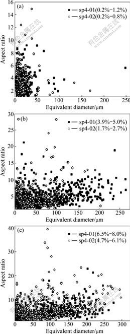
Fig.3 Aspect ratio variations as function of equivalent diameter: (a) sp4-01(0.2%-1.2%), sp4-02(0.2%-0.8%); (b) sp4-01 (3.9%-5.0%), sp4-02(1.7%-2.7%); (c) sp4-01(6.5%-8.0%), sp4-02(4.7%-6.1%)
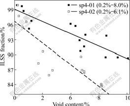
Fig.4 Interlaminar shear strength as function of void content
There is significant scatter in the strength data for the two laminates with the similar void content. This may be attributed to the shape and size of voids in the composite. The optical assessment of voids shows that the void sizes and shapes are different (Figs.2 and 3). So, void sizes and shapes play an important role to comprehensively evaluate the influence of voids on mechanical properties.
As can be seen in Fig.4, sp4-02 laminates have a higher void sensitivity. This may be due to the void shape. The aspect ratio of voids in sp4-02 laminates is always larger than that encountered in sp4-01 laminates at the similar equivalent diameter.
To study the effect of voids on the interlaminar shear failure, the tested specimens were sectioned to perform image analysis. Fig.5 shows the cracks emanating from the voids in both stacking sequence specimens with large void content after ILSS test. The initiation and propagation of the cracks are associated with voids. Crack propagation involves coalescence of the voids. Voids can also alter the direction of the crack (Fig.5(d)).
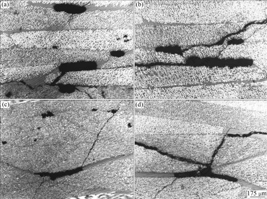
Fig.5 Micrographs of tested specimen with different void contents showing cracks emanating from voids: (a) sp4-01(3.9%); (b) sp4-01(6.5%); (c) sp4-02(1.7%); (d) sp4-02(4.7%)
4 Conclusions
1) The composite laminates with high porosity were manufactured using autoclave pressures of 0, 0.1 and 0.4 MPa. Because of the different stacking sequences, the shape and size distributions of voids in the two laminates are different from each other.
2) The ILSS decreases with increasing void content for the two laminates. But, the void sensitivity is different. The decreasing rate of ILSS is greater for the [(��45)/04/(0,90)/02]S laminates. There is significant scatter in both laminates. The scatter increases with increasing void content. This suggests that the shapes and sizes of voids play an important role to the higher void content.
3) Voids clearly influence the initiation and propagation of cracks in both stacking sequence laminates as the micrographs of tested specimen clearly show.
References
[1] CANTWELL W J, MORTON J. The significance of damage and defects and their detection in composites material: A review [J]. Journal of Strain Analysis, 1992, 27(1): 29-42.
[2] XU Ji-wei, LI Min, GU Yi-zhuo, ZHANG Zuo-guang. Quantitative measuring method and influencing factors of void formation conditions in thermosetting resins [J]. Acta Materiae Compositae Sinica, 2008, 25(2): 52-56. (in Chinese)
[3] COSTA M L, REZENDE MC, ALMEIDA S F M. Strength of hydrothermally conditioned polymer composites with voids [J]. Journal of Composite Materials, 2005, 39: 1943-1961.
[4] STONE D E, CLARK B. Ultrasonic attenuation as a measure of void content in carbon-fibre reinforced plastics [J]. Nondestructive Testing, 1975, 8(3): 137-145.
[5] HUANG H S, TALREJA R. Effects of void geometry on elastic properties of unidirectional fiber reinforced composites [J]. Composites Science and Technology, 2005, 65: 1964-1981.
[6] HAMIDI Y K, AKTAS L, ALTAN M C. Three-dimensional features of void morphology in resin transfer molded composites [J]. Composites Science and Technology, 2005, 65: 1306-1320.
[7] JUDD N C W, WRIGHT WW. Voids and their effects on the mechanical properties of composites��An appraisal [J]. SAMPE Journal, 1978, 14(1): 10-14.
[8] ALMEIDA S F M, NOGUEIRA-NETO Z S. Effects of void content on the strength of composite laminates [J]. Composite Structures, 1994, 28: 139-148.
[9] G?ERDAL Z, TOMASINO A P, BIQQERS S B. Effects of processing induced defects on laminate response: Interlaminar tensile strength [J]. SAMPE Journal, 1991, 27(4): 39-49.
[10] BOWLES K J, FRIMPONQ S. Void effects on the interlaminar shear strength of unidirectional graphite-fiber-reinforced composites [J]. Journal of Composite Materials, 1992, 26(10): 1487-1509.
[11] BAZHENOV S L, KUPERMAN A M, ZELENSKII E S, BERLIN A A. Compression failure of unidirectional glass-fibre-reinforced plastics [J]. Composites Science and Technology, 1992, 45(3): 201-208.
[12] LEE J, SOUTIS C. Thickness effect on the compressive strength of T800/924C carbon fibre-epoxy laminates [J]. Composites: Part A, 2005, 36: 213-227.
[13] OLIVIER P, COTTU J P, FERRET B. Effects of cure cycle pressure and voids on some mechanical properties of carbon/epoxy laminates [J]. Composites, 1995, 26(7): 509-515.
[14] CHAMBERS A R, EARL J S, SQUIRES C A, SUHOT M A. The effect of voids on the flexural fatigue performance of unidirectional carbon fibre composites developed for wind turbine applications [J]. International Journal of Fatigue, 2006, 28: 1389-1398.
[15] LIU Ling, ZHANG Bo-Ming, WANG Dian-Fu, WU Zhan-Jun. Effects of cure cycles on void content and mechanical properties of composite laminates [J]. Composite Structures, 2006, 73: 303-309.
[16] HAGSTRAND P O, BONJOUR F, M?NNSON J A E. The influence of void content on the structural flexural performance of unidirectional glass fibre reinforced polypropylene composites [J]. Composites Part A, 2005, 36: 705-714.
[17] COSTA M L, ALMEIDA S F M, REZENDE M C. The influence of porosity on the interlaminar shear strength of carbon/epoxy and carbon/bismaleimide fabric laminates [J]. Composite Science and Technology, 2001, 61(14): 2101-2108.
[18] JEONG H. Effects of voids on the mechanical strength ultrasonic attenuation of laminated composites [J]. Journal of Composite Materials, 1997, 31(3): 276-292.
[19] WISNOM M R, REYNOLDS T, GWILLAM. Reduction in interlaminar shear strength by discrete and distributed voids [J]. Composite Science and Technology, 1996, 56(1): 93-101.
(Edited by YANG Hua)
Foundation item: Project supported by Harbin Aircraft Industry Co., Ltd., China
Corresponding author: ZHU Hong-yan; Tel: +86-451-86418802; E-mail: Hongyanzhu5@163.com

