Precision loss of ball screw mechanism under sliding-rolling mixed motion behavior
来源期刊:中南大学学报(英文版)2021年第5期
论文作者:程强 齐宝宝 李顺磊 刘志峰 杨聪彬
文章页码:1357 - 1376
Key words:ball screw mechanism; precision loss; sliding-rolling mixed motion; creep; lubrication
Abstract: The sliding-rolling mixed motion behavior degrades the ball screw’s precision at different levels. Based on the sliding-rolling mixed motion between ball and screw/nut raceway, the ball screw’s precision loss considering different given axial loading and rotational speed working conditions was investigated. Since creep and lubrication relate to sliding and rolling motion wear, the creep and lubrication characteristics are analyzed under different working conditions. Besides, the precision loss was calculated considering the sole influence of sliding behavior between ball and screw and compared with the results from other current models. Finally, research on precision loss owing to the sliding-rolling mixed motion behavior was realized under given working conditions, and suitable wear tests were carried out. The analytical results of precision loss are in good agreement with the experimental test conclusions, which is conducive to better predicting the law of precision loss in stable wear period.
Cite this article as: QI Bao-bao, CHENG Qiang, LI Shun-lei, LIU Zhi-feng, YANG Cong-bin. Precision loss of ball screw mechanism under sliding-rolling mixed motion behavior [J]. Journal of Central South University, 2021, 28(5): 1357-1376. DOI: https://doi.org/10.1007/s11771-020-4537-1.

J. Cent. South Univ. (2021) 28: 1357-1376
DOI: https://doi.org/10.1007/s11771-020-4537-1

QI Bao-bao(齐宝宝)1, 2, CHENG Qiang(程强)1, 2, LI Shun-lei(李顺磊)1, 3,LIU Zhi-feng(刘志峰)1, 3, YANG Cong-bin(杨聪彬)1, 3
1. Institute of Advanced Manufacturing and Intelligent Technology, Beijing University of Technology, Beijing 100124, China;
2. Beijing Key Laboratory of Advanced Manufacturing Technology, Beijing University of Technology, Beijing 100124, China;
3. Mechanical Industry Key Laboratory of Heavy Machine Tool Digital Design and Testing,Beijing University of Technology, Beijing 100124, China
 Central South University Press and Springer-Verlag GmbH Germany, part of Springer Nature 2021
Abstract: The sliding-rolling mixed motion behavior degrades the ball screw’s precision at different levels. Based on the sliding-rolling mixed motion between ball and screw/nut raceway, the ball screw’s precision loss considering different given axial loading and rotational speed working conditions was investigated. Since creep and lubrication relate to sliding and rolling motion wear, the creep and lubrication characteristics are analyzed under different working conditions. Besides, the precision loss was calculated considering the sole influence of sliding behavior between ball and screw and compared with the results from other current models. Finally, research on precision loss owing to the sliding-rolling mixed motion behavior was realized under given working conditions, and suitable wear tests were carried out. The analytical results of precision loss are in good agreement with the experimental test conclusions, which is conducive to better predicting the law of precision loss in stable wear period.
Key words: ball screw mechanism; precision loss; sliding-rolling mixed motion; creep; lubrication
Cite this article as: QI Bao-bao, CHENG Qiang, LI Shun-lei, LIU Zhi-feng, YANG Cong-bin. Precision loss of ball screw mechanism under sliding-rolling mixed motion behavior [J]. Journal of Central South University, 2021, 28(5): 1357-1376. DOI: https://doi.org/10.1007/s11771-020-4537-1.
1 Introduction
As driving functional components, ball screw mechanisms (BSMs) are among the most used components for precision equipment in various fields, such as machine tools [1]. The decline of the BSM precision level can restrict the accuracy level of precision equipment. Precision retention of ball screw refers to the ability to maintain precision at a certain precision level under specified operating conditions and times. However, the sliding-rolling mixed motion behavior influences the ball screw’s precision degradation at different degrees. Studies on BSM precision loss include precision degradation basics and analysis of precision degradation, revealing the law of precision degradation.
The basics of the BSM precision degradation include statics, kinematics [2-4], and dynamics [1, 5]. LIN et al [2] proposed the basic kinematic analysis method for ball screws. Further, WEI et al [3] improved the ball screws kinematic model based on LIN’s model by considering the effect of contact angle and elastic contact deformation on kinematics. The kinematics model [2] was applied to the optimization analysis of BSM transmission efficiency by LIN et al [4], and WEI et al [6] extended the transmission efficiency optimization model of the BSM based on LIN’s work. By considering the influence of preload and lubrication on contact kinematics, WEI et al [7] selected the preload-adjustable BSM as the research object. YANG et al [1] and LIU et al [5], respectively, studied the BSM feed dynamics control and dynamic performance optimization. Moreover, CHEN et al [8] established BMS’s contact stiffness considering the impact of the contact angle and helix’s rise angle on dynamics.
Besides, ZHAO et al [9], ZHEN et al [10], and LIN et al [11] studied the contact load distribution by considering the motion torque and geometric error. KANG [12] designed a series of experiments to detect the BSM friction torque models. Through creep analysis, XU et al [13] proposed a novel ball screw friction torque model. By considering the impact of preload on friction torque, ZHOU et al [14] selected the preload-adjustable BSM as the object of their experimental investigation. Finally, WEI et al [15] and KAMALZADEH et al [16] revealed the effects of preload and elastic deformation on the BSM wear rate.
At present, studies on BSM precision degradation are mainly performed from the perspective of sliding wear. According to the ball screw kinematics analysis results, there are two types of motion in BSM, rolling and sliding [14, 17, 18]. Based on ARCHARD’s [19] model, WEI et al [15], ZHOU et al [20], LIU et al [21], CHENG et al [22], and ZHOU et al [23] studied the BMS wear. ZHOU et al [20] and LIU et al [21] studied the screw precision degradation rate in line with wear model, and the BSM precision degradation due to wear result under time-varying working conditions was studied by CHENG et al [22]. The BSMs wear coefficient was obtained by ZHOU et al [23] through design experiments. LIU et al [24] developed a compensation method for thermal error. By detecting the motor current and the vibration signal of BSM, NGUYEN et al [25] realized the preload monitoring. CHENG et al [26] established the attenuation model of machine tool accuracy, considering the decline of transmission components accuracy. Then, CAI et al [27] and CHENG et al [28, 29] described the coordinate transformation relationship between two adjacent bodies in a multi-body system and established an accuracy prediction model for the vertical machining center [30, 31]. Moreover, the research results can be applied to the accuracy prediction of various machine tools.
Despite the progress, the degradation law of the ball screw’s positioning precision considering the effects of the sliding-rolling mixed motion behavior has not been studied, as well as the BSM precision degradation and its precision loss rate due to sliding-rolling mixed motion behavior. In order to update the study of precision loss, the BSM sliding-rolling mixed motion behavior considering given axial loading and rotational speed working conditions was studied in this paper. Furthermore, the BSM precision degradation and BSM precision loss rate were also gained in the light of the sliding-rolling mixed motion behavior in this study.
2 Ball screw mechanisms creep rate
Creep analysis is the basis for resolving the problem of the BSM rolling contact, including the BSM rolling friction [13] and the BSM rolling contact wear [32, 33]. This paper uses the BSM coordinate system shown in Figure 1 [13, 22].
O-XYZ is the global coordinate system, and Ob-TNB is the free coordinate system. Both S-xsyszs and N-xnynzn are local coordinate systems. For the meaning of other parameters in the figure, refer to the Nomenclature.
The creep rate of ball and nut along the xn and yn direction, i.e.,  xn and yn, according to KALKER’s linear creep [31], is expressed as follows:
 (1a)
(1a)
 (1b)
(1b)
where  and
and  are the components of ball spin angular velocity ωbr in the xn and yn directions, respectively. ωbr was obtained [34, 35]:
 (2)
(2)
Therefore, ωb-xn and ωb-yn can be written as:
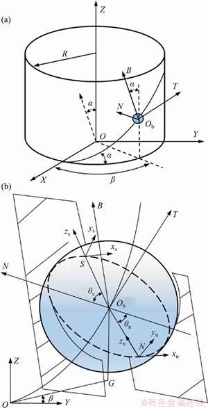
Figure 1 BSM global-contact coordinate system and transformation relationship between coordinates O-XYZ, Ob-TNB, S-xsyszs and N-xnynzn
 (3a)
(3a)
 (3b)
(3b)
The components ωN-xn and ωN-yn of nut’s angular velocity ωN in the xn and yn directions, respectively, are as follows:
 (4a)
(4a)
 (4b)
(4b)
The rolling speed between the ball and nut, ωb-N is:
 (5)
(5)
In the equations above, δni is the contact deformation between the i-th ball and the nut, expressed as follows:
 (6)
(6)
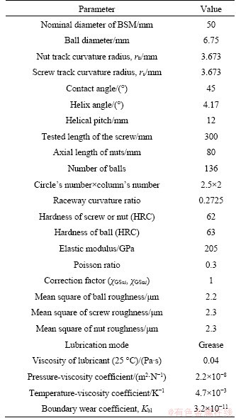
where χGSni (see Table 1) is the correction factor in the Hertz contact equation.
Table 1 Initial parameters of BSM
ωn, ωb and ωt are given as:
 (7a)
(7a)
 (7b)
(7b)
 (7c)
(7c)
ωN is nut’s angular velocity, expressed as:
 (8)
(8)
xn and yn are expressed as:


 (9a)
(9a)


 (9b)
(9b)
Similarly, based on Ref. [33], the creep rates between the ball and screw in the xs and ys directions, xs and ys, are expressed as:
 (10a)
(10a)
 (10b)
(10b)
where ωb-S is the rolling speed between the ball and screw, given by
 (11)
(11)
The angular velocity components of ball or screw in the xs and ys directions, namely ωb-xs, ωb-ys or ωS-xs, ωS-ys, can be calculated as:
 (12a)
(12a)
 (12b)
(12b)
 (13a)
(13a)
 (13b)
(13b)
where δsi is the contact deformation between the i-th ball and the screw, expressed as:
 (14)
(14)
where rs is is the track curvature radii of the screw.
Finally, xs and ys are expressed as:


 (15a)
(15a)
 (15b)
(15b)
3 Ball screw mechanisms lubrication analysis
The lubricant film thickness and contact surface roughness have diverse degrees of influence on the wear coefficient [36]. Figure 2 shows the BSM lubrication analysis diagram.
According to Ref. [7], the lubricant film thickness between the ball and the raceway hb-k can be written as follows:
 (16)
(16)
where hcb-k (k=s or n) is the contact center lubricant thickness between the ball and screw or the nut that can be obtained from Ref. [35]. R1 or R2 is the curvature sum of ball and screw or ball and nut, and eb-k (ik, jk) is the elastic deformation of ball and screw and that of ball and nut [37].

 (17a)
(17a)

 (17b)
(17b)
 (18)
(18)
 (19)
(19)
where Ub-s and Ub-n are the dimensionless velocity between the ball and screw and that between the ball and nut [34]; Gb-s and Gb-n are the BSM material parameters and relate to the pressure-viscosity coefficient of lubricant, γ; Wb-s and Wb-n are dimensionless contact loading; Ds and Dn are the inner diameter of screw and that of the nut, respectively; E* is the equivalent elastic modulus of the ball and the raceway.

Figure 2 Lubricated contact status between ball and raceway
 (20a)
(20a)
 (20b)
(20b)
 (21)
(21)
 (22a)
(22a)
 (22b)
(22b)
 (23)
(23)
where ηvs and ηvn are the lubricant’s dynamic viscosity. The relationship between viscosity, pressure, and temperature is as follows[38]:
 (24a)
(24a)
 (24b)
(24b)
where ηvs,0 is the lubricant’s viscosity at temperature Tvs,0; ηvn,0 is the lubricant’s viscosity at temperature Tvn,0; γ/λ is the pressure-viscosity coefficient of lubricant (Table 1); λ is the temperature-viscosity coefficient of lubricant (Table 1); Fsi and Fni are contact loadings between the i-th ball and screw and nut, respectively.
Moreover, ub-s and ub-n are the average sliding velocity in S-xsyszs and N-xnynzn, respectively:
 (25a)
(25a)
 (25b)
(25b)
where vb-xs and vb-ys are the components of the ball velocity in the xs and ys direction, respectively; vs-xs and vs-ys are the components of the screw speed in the xs and ys directions, respectively; vb-xn and vb-yn are the components of the ball velocity in the xn and yn directions, respectively; vn-xn and vn-yn are the components of the nut speed in the xn and yn directions, respectively. These terms are expressed as follows:
 (26a)
(26a)
 (26b)
(26b)
 (27a)
(27a)
 (27b)
(27b)

 (28a)
(28a)

 (28b)
(28b)

 (29a)
(29a)

 (29b)
(29b)
In the above equations, the term vb-s is ball’s rotational speed relative to screw in the helical direction [3], given by

 (30)
(30)
By combining Eqs. (16a)-(18b), the minimum lubricant film thickness hminb-s and hminb-n can be written as:
 (31a)
(31a)
 (31b)
(31b)
In line with the minimum lubricant thickness and the mean square roughness of contact surface, this study introduced the parameter Φ to describe the BSM lubrication state as follows:
 (32)
(32)
where σb and σl are the mean-square roughness values of the ball and the raceway, respectively. When hmin=hminb-s and σl=σs, Eq. (32) expresses the lubrication parameter of ball and screw; when hmin=hminb-n and σl=σn, Eq. (32) is the lubrication parameter of the ball and nut.
The roughness morphology and profile heights of the raceways and balls can be obtained through three-dimensional surface topography technique using a three-dimensional topography signal instrument. Figure 3 shows the measured micro-morphology signal of the screw raceway, and Table 1 summarizes the mean-square value of the roughness. This paper assumes that the screw raceway and nut raceway have the same roughness value. Similarly, the mean square roughness value of the ball was also obtained.
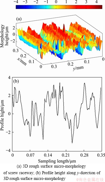
Figure 3 Three-dimensional micro-morphology signal of screw raceway:
The relationship between the BSM wear coefficient kd and lubrication parameter Φ is as follows [37]:
 (33)
(33)
where kbl is the BSM wear coefficient under the boundary lubrication state (see Table 1).
4 Precision degradation calculation
According to the mixed motion analysis, this study calculates the BSM precision degradation for the sliding and rolling motion separately.
4.1 Precision degradation due to sliding motion wear
According to the Archard model [19], the sliding wear amount can be expressed as follows:
 (34)
(34)
where Cb-s and Cb-n are the total cycles of the ball and screw, and the ball and nut, respectively; Vb-s(n) and Vb-n(n) are the wear amount of the ball and screw, and the ball and nut, respectively, in one cycle.
 (35a)
(35a)
 (35b)
(35b)
where V1b-s(t) and V1b-n(t) are the wear amount of the first ball and screw and that of the first ball and nut during one cycle.

 (36a)
(36a)

 (36b)
(36b)
where are the wear amounts of ball and screw from tss1 to tss2, from tssi to tssi+1 and from tssM to tss1 in Eq. (37a);
  are the wear amounts of ball and nut from tns1 to tns2, from tnsi to tnsi+1 and from tnsM to tns1 in Eq. (37b):
 (37a)
(37a)
 (37b)
(37b)
where 


 are the wear amounts of ball and screw/nut at tss1, …tssi …tssM/tns1, …tnsi…tnsM in Eqs. (38a) and (38b). And Fs1, …, Fsi…, FsM/Fn1, …Fni …FnM are the contact loadings of each ball and screw/nut.
 (38a)
(38a)
 (38b)
(38b)
where

 and
and
 …,
…,  are the screw and nut sliding distances relative to the 1st, 2nd, …, M-th ball. By taking the i-th ball as an example, one obtains:

 (39a)
(39a)

 (39b)
(39b)
where Rbsi and Rbni are the sliding-to-rolling ratios of the i-th ball and screw, and that of the i-th ball and nut, respectively. Based on Ref. [22], Rbsi and Rbni can be calculated:


 (40)
(40)


 (41)
(41)
By combining Eqs. (37a)-(41), one can calculate  …,
…, …,
…, and
and  …,
…,  …,
…,  Moreover, the sliding wear amount is obtained by bringing Eqs. (36a) and (36b) into Eqs. (35a), (35b) and (34). Based on Eqs. (34) and (36b), the sliding wear depth of ball and screw/nut is given as:
 (42a)
(42a)
 (42b)
(42b)
where hsbs(n) and hsbn(n) are the screw raceway length and that of nut raceway; abs is the contact surface long half axes of ball and screw, and bbs is the contact surface short half axes of ball and screw; abn is the contact surface long half axes of ball and nut; bbn is the contact surface short half axes of ball and nut. The length of the raceway of the screw is  and the length of the raceway of the nut is
According to Refs. [21, 39], the contact area can be established:
 (43)
(43)
When k=s, Eq. (43) gives the contact area of ball and screw; when k=n, Eq. (43) gives the contact area of the ball and nut.
The calculation of contact loading was demonstrated. MEI et al [40] established the calculation model for the BSM contact loading. ZHAO et al [9], ZHEN et al [10], and LIN et al [11] studied the contact load distribution by considering the motion torque and geometric error. By considering the preload, WEI et al [7] pointed out the contact state between ball and raceway under different preloads; furthermore, based on the contact state, LI et al [41] conceptualized the correlation among contact loading, axial loading, and preload. Based on Refs. [40], [7] and [41], this paper calculates the contact loading between the ball and screw/nut considering the preload attenuation.
According to Refs. [7, 41], the contact state between ball and raceway can be represented as shown in Figure 4. In Figure 4(a), the axial loading is higher than 2.83 times of preload; in Figure 4(b), the axial loading is lower than 2.83 times of preload. When the axial loading almost equals the preload, BSM is not suitable for precision transmission [7]. Therefore, the study does not discuss this situation.
In Figure 4(a), F1a is the total contact loading among balls, screw, and nut 1 raceway; F2a is the total contact loading among balls, screw, and nut 2 raceway, and they can be written as follows:
 (44)
(44)
Similarly, F1a and F2a in Figure 4(b) are:
 (45)
(45)
According to Ref. [40], Fsi and Fni (i=1, …, M) can be obtained as:
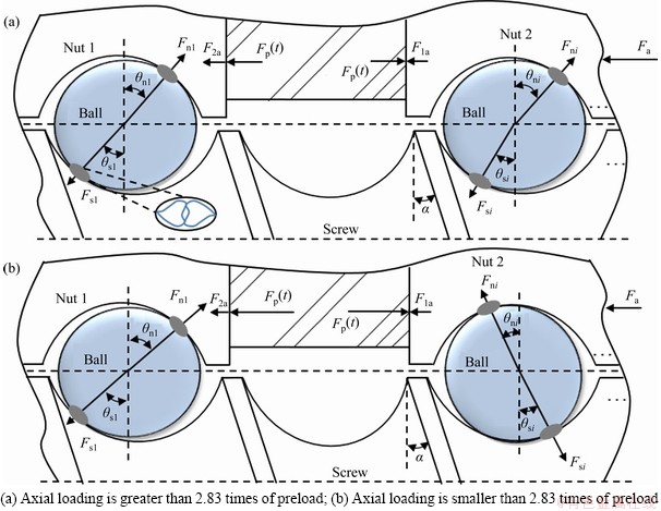
Figure 4 Contact state:
 (46a)
(46a)
 (46b)
(46b)
where Fp(t) can be obtained from Ref. [42]. In contact state in Figure 4(a), when the ball contacts nut 1,  when the ball contacts nut 2,
 In contact state in Figure 4(b), when the ball contacts nut 1,
  when the ball contacts with nut 2,
  For the detailed calculations, refer to Refs. [40, 7, 41, 42].
4.2 Precision degradation due to rolling motion wear
In the rolling motion contact area of ball and raceway, there are partial sliding and partial adhesion phenomena [32, 33]. Figure 5 shows a schematic of rolling motion contact of ball and screw/nut raceways.
Based on Ref. [32], the rolling wear depth of single ball and screw is deduced:
 (47)
(47)
where kbs is the dimension wear coefficient, kbs=kd/Hb-s; according to Eq. (44), A()≈akbk/9; vrbs is the creep velocity.
At time ti, the wear depth is given owing to rolling motion as:
 (48)
(48)
where Sbs is the creep value in rolling motion contact.
By combining Eqs. (47) and (48), the accumulative wear depth owing to rolling motion behavior in the xs direction can be obtained:
 (49)
(49)
where  is the sliding velocity between ball and screw in the xs direction given by:
 (50)
(50)
In Eq. (50),  is the average rolling velocity of ball and screw in the xs direction calculated by combining Eqs. (12a) and (13a).

Figure 5 Rolling motion contact of ball and screw/nut raceway: Partial slip and partial stick regions

 (51)
(51)
By combining Eqs. (49)-(51), Eq. (48) was deduced as:
 (52)
(52)
In Figure 5, at contact point Axs,  and at contact point Cxs,
By considering the rolling cycles number,  is expressed as:
 (53)
(53)
Similarly, the rolling wear depth in the ys direction can be obtained:
 (54)
(54)
The term  is the sliding velocity between ball and screw in the ys direction, given by
 (55)
(55)
where  is the average rolling velocity of ball and screw in the ys direction calculated by combining Eqs. (12b) and (13b) as:
 (56)
(56)
Similarly, the cumulative rolling wear depth of ball and nut in the xn and yn direction is obtained:
 (57a)
(57a)
 (57b)
(57b)
The sliding velocities of ball and nut in the xn and yn direction, i.e.,  and
and  in Eqs. (57a) and (57b), can be calculated:
 (58a)
(58a)
 (58b)
(58b)
where xn and yn are the creep rate of ball and screw in the xn and yn directions given by Eqs. (9a) and (9b), respectively. The terms  and
and  are the average rolling velocity of ball and nut in the xn and yn directions calculated according to Eqs. (3a), (4a), and Eqs. (3b) and (4b):

 (59a)
(59a)
 (59b)
(59b)
Considering the rolling cycles number and combining Eqs. (57a) and (57b),  and
and  are given by Eqs. (60a) and (60b), respectively:
 (60a)
(60a)
 (60b)
(60b)
where  and are the rolling wear depths of ball and nut in the xn and yn directions, respectively, when the number of the ball rolling cycles is (n-1). In Figure 5, at contact point Axn,
  at contact point Cxn,
  At contact point Ayn,
  and at contact point Cyn,
5 Analysis of BSM precision loss
5.1 Working conditions on precision loss
Figure 6 shows the flowchart of the whole calculation process. When the ball is at different phase angles, the creep rate between ball and screw/nuts varies with the operating conditions (i.e., axial loading and rotational speed). The BSM lead and raceway curvature ratios were obtained from Table 1. The variation of the creep rate with the axial loading can be investigated based on the creep calculation presented in Section 2; the rotational speed of the screw was set to 60 r/min, and the initial preload was set to 2500 N. Besides, the law of the BSM creep rate can be obtained considering the different axial loading conditions in Figures 7(a)-(d). Similarly, the BSM lead was 20 mm, and the raceway curvature ratio was 0.2725 based on Table 1. When the axial loading was set to 2000 N, and the initial preload was 2500 N, the creep rate was obtained considering the different rotational speeds in Figures 7(e)-(h).
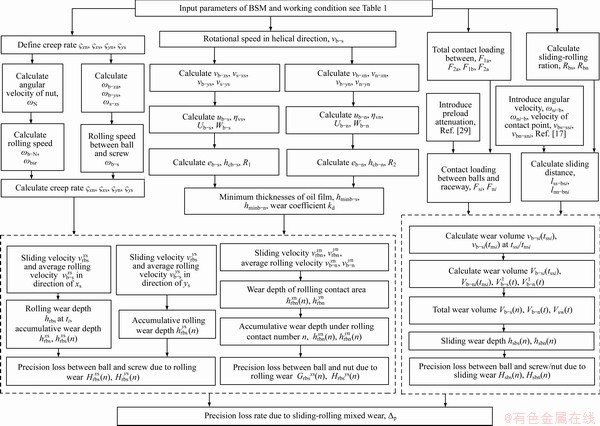
Figure 6 Flowchart of calculation process for BSM precision loss and precision loss rate
In Figures 7(a) and (b), the changing characteristics of the creep rate between the ball and the screw raceway are consistent with those of the contact angle. That is, the creep rate between the ball and the screw raceway decreases with reducing contact angle. Also, the creep rate decreases with the increase of the axial load. However, the contact angle θn between the ball and the nut raceway increases as the axial load increases. Therefore, in Figures 7(c) and (d), the changing characteristics of the creep rate between the ball and the nut raceway are also consistent with the changing characteristics of the contact angle. That is, the absolute value of the creep rate between the ball and the nut increases as the contact angle increases, and it became more significant as the axial load increases.
In Figures 7(e)-(h), because of the ball spin angular velocity, the rolling speed between ball and screw/nut relates to the contact angle. When the rotational speed of the screw increases, the contact angle θs becomes larger. Therefore, in Figures 7(e) and (f), the changing characteristics of the creep rate between the ball and the screw raceway are consistent with the changing characteristics of the contact angle. That is, the creep rate between the ball and the screw enlarges as the contact angle increases. The performance result was that the creep rate increased with the increase of the screw rotation speed. However, the contact angle θn becomes small as the screw rotation speed increases. Therefore, in Figures 7(g) and (h), the changing characteristics of the creep rate between the ball and the nut raceway are also consistent with those of the contact angle. That is, the absolute value of the creep rate between the ball and the screw becomes smaller as the contact angle decreases. Also, as the screw rotation speed increases, the creep rate reduces.
Using KOC301 lubricant, the lubricant viscosities ηvs and ηvn can be calculated from Eqs. 24(a) and (b). According to Figures 8(a) and (b), both the rotational speed and the axial loading have certain influences on the minimum lubricant film thickness between ball and screw/nut. However, the influence of the rotational speed is more significant than that of the axial loading. Also, the minimum film thickness between the ball and nut is slightly larger than that between ball and screw, because with the increase of the rotational speed and centrifugal force, the minimum lubricant thickness between ball and nut was increased more than that between ball and screw. As the axial loading increases, the contact loading of the ball and screw/nut also increases. Therefore, the minimum lubricant film thickness of the ball and screw/nut reduces.
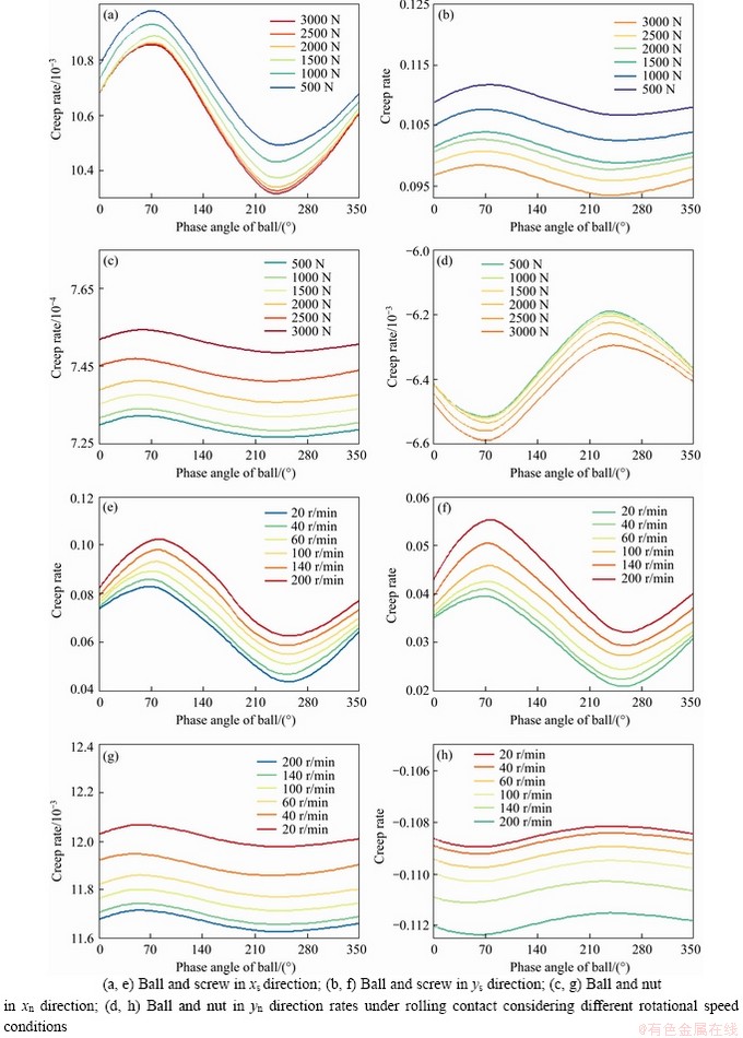
Figure 7 BSM creep rates under rolling contact considering different axial loading conditions (a, b, c, d) and rotational speed conditions (e, f, g, h):
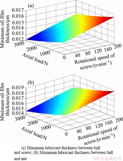
Figure 8 BSM minimum lubricant film thickness under different rotational speed and axial loading working conditions:
In this study, when the ball moved from the ith ball position to the (i+1)th ball position, the sliding length of screw/nut relative to the original contact point is called the sliding distance. Axial loading and rotational speed have different degrees of influence on the sliding distance. When the initial preload was 2500 N, by combining Eqs. (39a)-(41), the sliding distance of ball and screw/nut is obtained (see Figure 9) considering the effects of axial loading and rotational speed.
According to Figure 9, both the axial loading and rotational speed of the screw have different degrees of influence on the BSM sliding distance. However, compared to the effect of axial loading on the sliding distance, the effect of the rotational speed is more significant. Also, the sliding distance on the screw is greater than that on the nut. The reason for this phenomenon is the transmission principle of BSM; that is, the movement of the screw drives the ball, and in turn, drives the nut to move. When a sliding movement exists between the ball and the screw raceway, it directly affects the movement between the ball and nut. It causes sliding-to-rolling ratio Rbs between the ball and the screw greater than the Rbn between ball and nut. Therefore, the sliding distance between the ball and screw is more significant than that between the ball and nut.

Figure 9 BSM sliding distance at different rotational speed and axial loading working conditions:
5.2 Experimental tests for evaluating precision loss
According to Refs. [6, 20-22], the cumulative wear depth in the stroke direction corresponds to the BSM precision loss value. By combining Eqs. (42a) and (43), the BSM precision degradation owing to the accumulated sliding motion wear depth of ball and screw/nut can be obtained:
 (61a)
(61a)
 (61b)
(61b)
Compared with WEI’s [6], ZHOU’s [20], and LIU’s [21] models, the BSM precision loss due to sliding motion wear of ball and screw was obtained. Based on Eq. 61(b), the precision loss due to the accumulated sliding motion wear between ball and nut in the stroke direction can also be gained. Figure 10 shows the BSM precision loss due to sliding motion wear.

Figure 10 BSM precision loss due to sliding motion wear:
By combining Eqs. (9), (15) and (22), the BSM creep rate can be calculated considering the operating conditions. The BSM creep characteristics were obtained at different axial loadings (see Figures 7(a)-(d)) and at different rotational speeds (Figures 7(e)-(h)). Based on Eqs. (47)-(52), the rolling motion wear depth of single ball and screw was obtained. Then, according to Eq. (53), the accumulated rolling motion wear depth of all effective transmission balls and screw in the xs direction is given by Eq. (62).
 (62)
(62)
Similarly, according to Eq. (54), the accumulated rolling motion wear depth of all effective transmission balls and screw in the ys direction was also obtained:
 (63)
(63)
Figure 11(a) shows the variation trend of BSM cumulative rolling motion wear depth obtained by combining Eqs. (62) and (63). Similarly, according to Eqs. (60a) and (60b), the cumulated rolling motion wear depth of all effective transmission balls and nut in the xn and yn directions can be written by Eq. (64), and Figure 11(b) shows its variation law.

Figure 11 BSM precision loss due to rolling motion wear:
Similarly, according to Eqs. (61), the accumulated wear depth of all effective transmission balls and nut in xn/yn direction can be written as follows:
 (64a)
(64a)
 (64b)
(64b)
In order to obtain the amount of precision loss when the BSM runs in a stable operating state, the BSM after fully running-in was selected as the experimental object. The positioning error after running was taken as the initial precision value. The experiments were performed using a test platform and a laser interferometer (XD Dual Frequency Laser Interferometer).
The positioning precision of the BSM after the wear test was measured. The difference between the test value and the initial value was the precision loss due to sliding-rolling mixed motion behavior. The following experimental conditions were established: axial loading of 2000 N, rotational speed of 60 r/min, grease-type lubrication using KOC301 lubricant, ambient temperature of 23 °C, test overall duration of 160 h. By combining Eq. (61a) with Eq. (64b), the test process and test results due to sliding-rolling mixed motion were obtained (see Figure 12).

Figure 12 BSM precision loss due to sliding-rolling mixed motion behavior
ZHOU et al [20] and LIU et al [21] established the BSM precision loss model due to screw sliding motion, mainly focusing on screw precision degradation. However, since the screw, nut and ball have different degrees of precision degradation, this study focuses on the BSM precision degradation due to sliding-rolling mixed motion behavior. According to Refs. [20, 21] and combining Eqs. (61a)-(64b), the BSM precision degradation, and precision loss rate were obtained in Eq. (65). Figure 13 shows the total precision loss rate for the BSM.

Figure 13 Total precision loss rate of BSM due to sliding-rolling mixed motion behavior
 (65)
(65)
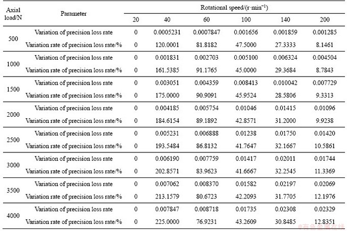
In Figure 13, both the axial loading and rotational speed have different degrees of impact on the BSM precision loss rate. Therefore, a quantitative analysis of the influence degree of axial load and rotational speed on the BSM precision loss rate is required. At a given screw speed, this study uses the variation of the precision loss rate and the variation rate of the precision loss rate to analyze the influence degree of axial load conditions on the precision loss rate. Table 2 summarizes the calculation results. In order to facilitate the quantitative analysis, the accuracy loss rate under an axial load of 500 N was used as a reference.
When analyzing the influence degree of the rotation speed on the accuracy loss rate, it was more reasonable to use the variation rate of the precision loss rate as the quantitative analysis index since the increase rate of the screw rotation speed was different. The variation of the precision loss rate was an intermediate value for calculating the variation rate of the precision loss rate, and it was also essential. In order to facilitate the quantitative analysis, the precision loss rate at a rotational speed of 20 r/min was used as a reference point. Note that due to the different increase in the screw rotation speed, that is, when the increment of the rotation speed was 40 or 60 r/min, it was necessary to divide by the multiple (2 or 3) of the rotation speed increment when calculating the variation rate of the precision loss rate. After that, the criteria for the unified quantitative analysis can be obtained (Table 3).
From Figure 13 and Table 2, at a given rotational speed, the precision loss rate increases with the increase of axial load. However, when the axial load increases by the same amplitude, the variation (increased amount) of the precision loss rate gradually decreases, and the variation rate of precision loss rate gradually decreases. The reason is that as the axial load increases, the contact angle between the ball and the screw decreases. As a result, the contact load between the ball and screw enlarges, and so does the precision loss rate between the ball and screw. However, the contact angle between the ball and the nut increases so that the contact load between the ball and the nut becomes smaller, resulting in the precision loss rate between the ball and nut also becoming smaller. Therefore, when the axial load increases, although the precision loss rate enlarges, the change value (increased amount) of the total precision loss rate of the ball screw decreases, and the variation rate of the precision loss rate gradually decreases.
At a given screw rotation speed, the increase in the precision loss rate is the maximum when the axial load changes from 500 to 1000 N. Moreover, the variation rate (increase rate) of the accuracy loss rate also reaches the maximum at 1000 N axial load. As the axial load increases, the amplitudes of attenuation of the variation value and the variation rate of the BSM precision loss are different. In particular, through the variation rate of precision loss rate, it is more convenient to analyze the change law of precision loss rate quantitatively.
According to the analysis of Figure 13 and Table 3, at a given axial load, the precision loss rate enlarges as the screw rotation speed increases. However, as the rotation speed gradually increases, the increase rate of the precision loss rate gradually decreases. On the one hand, due to the increase in rotation speed, the sliding motion velocity becomes more significant and so does the sliding motion distance (Eq. (39) and Figure 9), resulting in the accelerated sliding motion wear, and the increased precision loss and precision loss rate. On the other hand, as the rotational speed of the screw increases, the contact angle between the ball and the nut decreases. The contact load between the ball and the nut increases, increasing the precision loss rate between the ball and nut. However, the contact angle between ball and screw increases, so that the contact load between ball and screw reduces. Also, the precision loss rate between the ball and screw reduces. Therefore, when the rotation speed increases, although the precision loss rate becomes larger, the variation rate (increase rate) of the total precision loss rate of the BSM decreases.
Table 2 Influence degree of axial load conditions on BSM precision loss rate
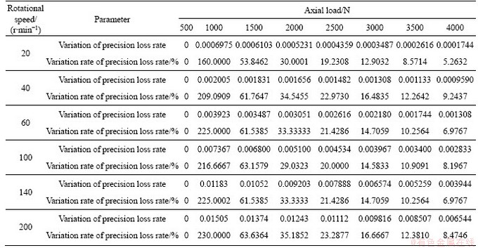
Table 3 Influence degree of rotational speed conditions on BSM precision loss rate
At a given axial load, the variation rate of the precision loss rate reaches its maximum when the screw rotation speed changes from 20 to 40 r/min. When the speed is 40 r/min, as the axial load increases, the increase rate in the precision loss rate gradually becomes larger. Furthermore, at the 4000 N axial load, the increase rate of the precision loss rate is the maximum. As the screw rotation speed increases, the variation value and variation rate of the BSM precision loss rate have different amplitudes of attenuation. Especially through the variation rate of the precision loss rate, it was more convenient to quantitatively analyze the influence degree of the rotation speed on the BSM precision loss rate.
6 Conclusions
1) Under the action of sliding motion, the precision loss value of the screw is greater than that of nut, because the sliding distance between the ball and the screw is greater than that between the ball and the nut. The sliding motion wear depth between ball and screw contributes a large proportion to the BSM precision loss.
2) The precision loss value under rolling motion occupies a certain proportion of the precision loss value under sliding motion, and the precision loss value under rolling motion is a part of the total precision loss of the ball screw. The precision loss value due to rolling motion has a certain level of influence on the BSM total precision loss.
3) As the rotation speed gradually increases, the increase rate of the precision loss rate gradually decreases. The rotation speed had a certain effect on the contact angle and could increase the sliding velocity, resulting in the increase of precision loss rate.
Contributors
QI Bao-bao provided the data curation, methodology and writing-original draft. CHENG Qiang provided the funding acquisition and methodology. LI Shun-lei replied to reviewers’ comments and revised the final version. LIU Zhi-feng conducted the formal analysis and funding acquisition. YANG Cong-bin provided the software.
Conflict of interest
QI Bao-bao, CHENG Qiang, LI Shun-lei, LIU Zhi-feng and YANG Cong-bin declare that they have no conflict of interest.
References
[1] YANG Y, ZHANG W M, ZHU Q X, JIANG Q S. Dynamic characteristic optimization of ball screw feed drive in machine tool based on modal extraction of state space model [J]. IEEE Access, 2019, 7: 55524-55542. DOI: 10.1109/ACCESS.2019. 2909550.
[2] LIN M C, RAVANI B, VELINSKY S A. Kinematics of the ball screw mechanism [J]. Journal of Mechanical Design, 1994, 116(3): 849-855. DOI: 10.1115/1.2919459.
[3] WEI C C, LIN J F. Kinematic analysis of the ball screw mechanism considering variable contact angles and elastic deformations [J]. Journal of Mechanical Design, 2003, 125(4): 717-733. DOI: 10.1115/1.1623761.
[4] LIN M C, VELINSKY S A, RAVANI B. Design of the ball screw mechanism for optimal efficiency [J]. Journal of Mechanical Design, 1994, 116(3): 856-861. DOI: 10.1115/ 1.2919460.
[5] LIU H, ZHANG J, ZHAO W. An intelligent non-collocated control strategy for ball-screw feed drives with dynamic variations [J]. Engineering, 2017, 3(5): 641-647. DOI: 10.1016/J.ENG.2017.04.007.
[6] WEI C, LAI R. Kinematical analyses and transmission efficiency of a preloaded ball screw operating at high rotational speeds [J]. Mechanism and Machine Theory, 2011, 46(7): 880-898. DOI: 10.1016/j.mechmachtheory.2011. 02.009.
[7] WEI C C, LIN J F, HORNG J. Analysis of a ball screw with a preload and lubrication [J]. Tribology International, 2009, 42: 11-19. DOI: 10.1016/j.triboint. 2008.12.013.
[8] CHEN Yong-jiang, TANG Wen-cheng. Dynamic contact stiffness analysis of a double-nut ball screw based on quasi-static method [J]. Mechanism and Machine Theory, 2014, 73(3): 76-90. DOI: 10.1016/j.mechmachtheory.2013. 10.008.
[9] ZHAO J, LIN M, SONG X, GUO Q Z. Investigation of load distribution and deformations for ball screws with the effects of turning torque and geometric errors [J]. Mechanism and Machine Theory, 2019, 141: 95-116. DOI: 10.1016/ j.mechmachtheory.2019.07.006.
[10] ZHEN N, AN Q. Analysis of stress and fatigue life of ball screw with considering the dimension errors of balls [J]. International Journal of Mechanical Sciences, 2018, 137: 68-76. DOI: 10.1016/j.ijmecsci.2017.12. 038.
[11] LIN B, OKWUDIRE C E, WOU J S. Low order static load distribution model for ball screw mechanisms including effects of lateral deformation and geometric errors [J]. Journal of Mechanical Design, 2018, 140(2): 022301. DOI: 10.1115/ 1.4038071.
[12] KANG X M, WANG L. Experimental analysis of axial load internal circulation ball screw pair of friction torque and the impact [J]. Applied Mechanics and Materials, 2013, (401-403): 139-145. DOI: 10.4028/www.scientific.net/ AMM.401-403.139.
[13] XU N, TANG W, CHEN Y, BAO D, GUO Y. Modeling analysis and experimental study for the friction of a ball screw [J]. Mechanism and Machine Theory, 2015, 87: 57-69. DOI: 10.1016/j.mechmachtheory. 2014.12.019.
[14] ZHOU C, FENG H, CHEN Z, OU Y. Correlation between preload and no-load drag torque of ball screws [J]. International Journal of Machine Tools & Manufacture, 2016, 102: 35-40. DOI: 10.1016/j. ijmachtools.2015.11.010.
[15] WEI C C, LIOU W L, LAI R S. Wear analysis of the offset type preloaded ball-screw operating at high speed [J]. Wear, 2012, 292: 111-123. DOI: 10.1016/j.wear. 2012.05.024.
[16] KAMALZADEH A, GORDON D J, ERKORKMAZ K. Robust compensation of elastic deformations in ball screw drives [J]. International Journal of Machine Tools & Manufacture, 2010, 50(6): 559-574. DOI: 10.1016/ j.ijmachtools.2010.03.001.
[17] GNANAMOORTHY R, GOVINDARAIAN N, MUTOH Y. Effect of slid-roll ratio on the contact fatigue behavior of sintered and hardened steels [J]. Journal of Failure Analysis and Prevention, 2004, 4(2): 78-83. DOI: 10.1361/ 15477020419082.
[18] GOVINDARAJAN N, GNANAMOORTHY R. Rolling/ sliding contact fatigue life prediction of sintered and hardened steels [J]. Wear, 2007, 262(1, 2): 70-78. DOI: 10.1016/ j.wear.2006.03.053.
[19] ARCHARD J F. Contact and rubbing of flat surfaces [J]. Journal of Applied Physics, 1953, 24(8): 981-988. DOI: 10.1063/1.1721448.
[20] ZHOU C, OU Y, FENG H, CHE Z. Investigation of the precision loss for ball screw based on the modified Archard theory [J]. Industrial Lubrication and Tribology, 2017, 69(2): 166-173. DOI: 10.1108/ILT-12-2015-0204.
[21] LIU Jia-lan, CHI Ma, WANG Shi-long. Precision loss modeling method of ball screw pair [J]. Mechanical Systems and Signal Processing, 2020, 135: 106397. DOI: 10.1016/ j.ymssp.2019.106397.
[22] CHENG Q, QI BB, LIU Z F, ZHANG C X, XUE D Y. An accuracy degradation analysis of ball screw mechanism considering time-varying motion and loading working conditions [J]. Mechanism and Machine Theory, 2019, 134: 1-23. DOI: 10.1016/ j.mechmachtheory. 2018.12.024.
[23] ZHOU C G, ZHOU H X, FENG H T. Experimental analysis of the wear coefficient of double-nut ball screws [J]. Wear, 2020, 446: 203201. DOI: 10.1016/j. wear.2020.203201.
[24] LIU K, LIU H, LI T, WANG Y, SUN M, WU Y. Prediction of comprehensive thermal error of a preloaded ball screw on a gantry milling machine [J]. Journal of Manufacturing Science and Engineering, 2017, 140(2): 021004. DOI: 10.1115/1.4037236.
[25] NGUYEN T L, RO S K, PARK J W. Study of ball screw system preload monitoring during operation based on the motor current and screw-nut vibration [J]. Mechanical Systems and Signal Processing, 2019, 131: 18-32. DOI: 10.1016/j.ymssp.2019.05.036.
[26] CHENG Q, ZHAO H W, ZHAO Y S, SUN B W, GU P H. Machining accuracy reliability analysis of multi-axis machine tool based on Monte Carlo simulation [J]. Journal of Intelligent Manufacturing, 2018, 29(1): 191-209. DOI: 10.1007/s10845-015-1101-1.
[27] CAI L G, ZHANG Z L, CHENG Q, LIU Z F, GU P H. An approach to optimize the machining accuracy retainability of multi-axis NC machine tool based on robust design [J]. Precision Engineering, 2016, 43: 370-386. DOI: 10.1016/ j.precisioneng.2015.09.001.
[28] CHENG Q, FENG Q N, LIU Z F, GU P H, ZHANG G J. Sensitivity analysis of machining accuracy of multi-axis machine tool based on POE screw theory and Morris method [J]. The International Journal of Advanced Manufacturing Technology, 2016, 84(9-12): 2301-2318. DOI: 10.1007/ s00170-015-7791-x.
[29] CHENG Q, ZHAO H W, ZHANG G G, GU P H, CAI L G. An analytical approach for crucial geometric errors identification of multi-axis machine tool based on global sensitivity analysis [J]. International Journal of Advanced Manufacturing Technology, 2014(75): 107-121. DOI: 10.1007/s00170-014-6133-8.
[30] ZHANG Z L, CAI L G, CHENG Q, LIU Z F, GU P H. A geometric error budget method to improve machining accuracy reliability of multi-axis machine tools [J]. Journal of Intelligent Manufacturing, 2019, 30(2): 495-519. DOI: 10.1007/ s10845-016-1260-8.
[31] FAN J W, TAO H H, WU C J, PAN R, TANG Y H, LI Z S. Kinematic errors prediction for multi-axis machine tools’ guideways based on tolerance [J]. The International Journal of Advanced Manufacturing Technology, 2018, 98(5-8): 1131-1144. DOI: 10.1007/s00170-018-2335-9.
[32] RODRIGUEZ-TEMBLEQUE L, ABASCAL R, ALIABADI M H. A boundary element formulation for wear modeling on 3D contact and rolling-contact problems [J]. International Journal of Solids and Structures, 2010, 47(18, 19): 2600-2612. DOI: 10.1016/j.ijsolstr. 2010.05.021.
[33] KALKER J J, JOHNSON K L. Three-dimensional elastic bodies in rolling contact [J]. Journal of Applied Mechanics, 1993, 60(1): 34-45. DOI: 10.1007/978-94-015-7889-9.
[34] HOU K P, ZHU D, WEN S Z. An inverse solution to the point contact EHL problem under heavy load [J]. ASME Journal of Tribology, 1987, 109(3): 432-436. DOI: 10.1115/1.3261466.
[35] HAMROCK B J, DOWSON D. Isothermal elastohydrodynamic lubrication of point contacts: Part 3- Fully flooded results [J]. Journal of Lubrication Technology, Trans ASME, 1977, 99(2): 264-276. DOI: 10.1115/ 1.3453074.
[36] DING H, KAHRAMAN A. Interactions between nonlinear spur gear dynamics and surface wear [J]. Journal of Sound and Vibration, 2007, 307(3-5): 662-679. DOI: 10.1016/j.jsv.2007. 06.030.
[37] MARKHO P H. Highly accurate formulas for rapid calculation of the key geometrical parameters of elliptic Hertzian contacts [J]. ASME Journal of Tribology, 1988, 109(4): 640-647. DOI: 10.1115/ 1.3261525.
[38] LAUN H M. Pressure dependent viscosity and dissipative heating in capillary rheometry of polymer melts [J]. Rheologica Acta, 2003, 42(4): 295-308. DOI: 10.1007/ s00397-002-0291-6.
[39] SHIMIZU S, SHIMODA H, SHARMA C S. Re-evaluation of basic dynamic load rating and life formula for a ball screw [J]. Tribology Transactions, 2007, 50(1): 88-95. DOI: 10.1080/ 104020006011 05599.
[40] MEI X, TSUTSUMI M, TAO T, SUN N. Study on the load distribution of ball screws with errors [J]. Mechanism and Machine Theory, 2003, 38(11): 1257-1269. DOI: 10.1016/ S0094-114X(03)00070-3.
[41] VERL A, FREY S, HEINZE T. Double nut ball screw with improved operating characteristics[J]. CIRP Annals-Manufacturing Technology, 2014, 63(1): 361-364. DOI: 10.1016/j.cirp.2014.03.128.
[42] CHEN K, ZU L, WANG L. Prediction of preload attenuation of ball screw based on support vector machine [J]. Advances in Mechanical Engineering, 2018, 10(9): 1687814018799161. DOI: 10.1177/1687814018799161.
(Edited by FANG Jing-hua)
中文导读
滑-滚混合运动行为作用下的滚珠丝杠副精度损失
摘要:滑-滚混合运动行为在不同程度上会退化滚珠丝杠副的精度。基于滚珠与丝杠/螺母滚道之间的滑-滚混合运动分析,研究了滚珠丝杠副在不同轴向负载及旋转速度工况下的精度损失。由于滑动、滚动磨损与蠕滑、润滑紧密相关,研究了不同运行工况下蠕滑及润滑特性。此外,当探究滚珠与滚道之间的滑动运动行为对精度损失的影响时,计算了滚珠丝杠副的精度损失并对比了其他模型。最后,在给定运行工况下,研究了滑-滚混合运动下的精度损失,设计相关实验,对精度衰退模型进行验证。精度损失的分析结果与试验测试具有很好的吻合性,表明该模型能够很好地预测处于稳定磨损时期内的精度损失。
关键词:滚珠丝杠副;精度损失;滑-滚混合运动;蠕滑;润滑
Foundation item: Project(51975012) supported by the National Natural Science Foundation of China; Project(Z1511000003150138) supported by the Beijing Nova Program, China; Project(Z191100001119010) supported by the Shanghai Sailing Program, China; Project(2018ZX04033001-003) supported by the National Science and Technology Major Project, China
Received date: 2020-04-15; Accepted date: 2020-09-07
Corresponding author: CHENG Qiang, PhD, Professor; Tel: +86-15901009350; E-mail: chengqiang@bjut.edu.cn; ORCID: https://orcid. org/0000-0001-5446-3658

