A novel method of photographic geological logging based on parallel image sequence in small tunnel
��Դ�ڿ������ϴ�ѧѧ��(Ӣ�İ�)2016���8��
�������ߣ���� ë��� ������ ��� ������
����ҳ�룺2092 - 2100
Key words��close-range photogrammetry; tunnel; image correction; photographic geological logging
Abstract: Small tunnels such as engineering geological exploratory tunnels and mine roadways are generally narrow, which make the existing photographic geological logging technique inapplicable. Therefore, geological logging of exploratory tunnels has always been taking the method of manual sketch work which has low efficiency and poor informatization degree of products, and it is a technical issue requiring urgent settlement for geological logging of small tunnels. This paper proposes and studies novel methods of photographic geological logging suitable for small tunnels, including image acquisition, image orientation control, image geometric correction, unfolded image map generation and geological attitude measurement, etc. Experiments show that the method can meet the precision requirement of geological logging. The novel method helps to realize the fast acquisition and processing of image-based geological logging data for small tunnels, and the forms of logging result are more abundant and more applicable to informatized management and application of geological logging data.
J. Cent. South Univ. (2016) 23: 2092-2100
DOI: 10.1007/s11771-016-3265-z

MAO Yu-feng(��)1, 2, LI Hao(���)1, 2, HE Yan-lan(������)3, YANG Biao(���)1, WU Ming-fei(������)1
1. School of Earth Science and Engineering, Hohai University, Nanjing 210098, China;
2. Engineering Research Center for Rock-Soil Drilling & Excavation and Protection, Ministry of Education,Wuhan 430074, China;
3. Jiangsu Geologic Surveying and Mapping Institute, Nanjing 210008, China
 Central South University Press and Springer-Verlag Berlin Heidelberg 2016
Abstract: Small tunnels such as engineering geological exploratory tunnels and mine roadways are generally narrow, which make the existing photographic geological logging technique inapplicable. Therefore, geological logging of exploratory tunnels has always been taking the method of manual sketch work which has low efficiency and poor informatization degree of products, and it is a technical issue requiring urgent settlement for geological logging of small tunnels. This paper proposes and studies novel methods of photographic geological logging suitable for small tunnels, including image acquisition, image orientation control, image geometric correction, unfolded image map generation and geological attitude measurement, etc. Experiments show that the method can meet the precision requirement of geological logging. The novel method helps to realize the fast acquisition and processing of image-based geological logging data for small tunnels, and the forms of logging result are more abundant and more applicable to informatized management and application of geological logging data.
Key words: close-range photogrammetry; tunnel; image correction; photographic geological logging
1 Introduction
Geological logging is the processing procedure of technical description, measurement and recording for various geological phenomena at the rock excavation sections of tunnels, slide slopes and foundation pits in geological prospecting and exploratory. It can provide the necessary information for geological and mineral analysis, evaluation as well as the corresponding engineering design and development. Traditional geological logging mainly adopts manual geological sketch and depends on manual survey to draw the geological structure line and measure and mark the stratum structure geological attitude. It can provide detailed, accurate and reliable geological information, but such working way is with huge workload, high labor strengths, low precision of geological logging and slow information feedback. Meanwhile, the traditional geological logging products are not conductive to statistical analysis and sharing application, and unsuitable for the development of modern productivity and the needs of fast response to geological information in modern projects.
The discussion on fast, efficient and accurate technical methods of geological logging to facilitate the result management and application has become an important topic in this research field. Digital close-range photogrammetry is a useful technique for carrying out detailed surveys of geometrical-structural settings even in inaccessible sites [1-5], and it can be used for slope stability monitoring and analysis [6-12]. Photographic geological logging is a practical technique emerging in recent years, which has settled the logging problems for geological projects such as tunnels, slide slopes and foundation pits [13-17], and improved the automatization and informatization degree of geological logging considerably. However, compared with large tunnels, engineering geological exploratory tunnel, as well as mine roadways, is a special type with extremely narrow space. The existing photographic geological logging techniques are applicable to large tunnels. If the existing photographic geological logging methods are applied to small tunnels directly, it will greatly reduce operation efficiency because of the small coverage area when photographing the tunnel surface and thus the existing method is inapplicable. Therefore, specific to small tunnels, the research and development of new techniques and new methods for photographic geological logging is needed for the settlement of technical issues such as the convenient image orientation control, fast image acquisition, image geometric correction, automatic generation of unfolded image map, and image-based digital geological logging, so as to form the rapid photographic geological logging technique for small tunnels. Generally, the photographic geological logging workflow for tunnel is described in Fig. 1 [17].

Fig. 1 Work flow of photographic geological logging for tunnels
2 Image data collection
2.1 Image orientation control method
Considering that neither is it appropriate to adopt the image orientation control method of the photographic logging instrument [17] in small tunnels, nor is it appropriate to set and measure the control points on the wall of tunnel, the control method by a special mobile control tripod is used as the photographic geological logging image orientation control method of small tunnels in this work. According to the characteristics of image acquisition for small tunnels and the geological logging requirements, we design a special mobile control tripod, as shown in Fig. 2.
The control tripod includes two parts. The one part is a tripod supporting the control device, and the other part is the control device which is mainly composed of a self-balancing base, a vertical rod (including two micro laser direction indicators) and cross rods (including six targets). The two micro laser indicators are used to realize the rapid orientation and location of the control tripod. The mobile control tripod is convenient forcarrying and assembling. Since the mobile control tripod can be placed in the tunnel engineering coordinate system on site, the elements of exterior orientation of each image can be calculated through the object and image coordinates of the six control points.
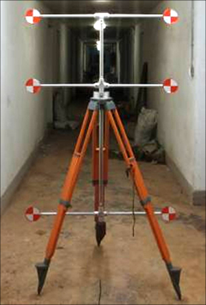
Fig. 2 A special mobile control tripod
The relative relationship among control points is fixed and can be measured in advance. It is only needed to place the mobile control tripod in the tunnel engineering coordinate system, and set the correct position and direction of the control tripod. The orientation of the control tripod is realized by the micro laser indicator on the vertical rod, aiming the micro laser indicator toward the starting point on the tunnel axis; orientation is to determine the position of the six control points. Automatic self-balancing base will ensure that the plane including six control points is vertical to the horizontal plane. Aiming the directional laser toward the X-axis direction of the tunnel engineering coordinate system (generally the tunnel axis) can ensure that the plane including six control points is vertical to X-axis, thus completing the fast determination of parameters of the control points.
2.2 Image acquisition
In this work, image acquisition of small tunnels based on the mobile control tripod is very convenient. The operator could hold the camera by hand and take photos toward the mobile control tripod along the tunnel axis in every certain distance, and then the parallel image sequence can be obtained, as shown in Fig. 3. The control tripod is commonly used by one parallel image sequence in every certain distance in the tunnel. Then, the control tripod is moved forward along the tunnel axis and put on a new position. Such image acquisition method is totally different from the existing photographic geological logging method suitable for large and medium tunnels [17]. This method is suitable for the imageacquisition in narrow tunnels with the use of simple devices (a consumer-level camera and the tripod), and the operation process is fast and convenient.
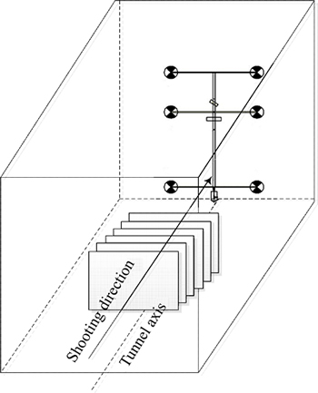
Fig. 3 Parallel image sequence acquisition
3 Image data processing
3.1 Image preprocessing
A consumer-level camera after calibration is adopted for photographic geological logging of tunnels. The elements of interior orientation and the calibration parameters of the photogrammetric distortion of the digital camera have been calculated. In this work, image preprocessing for photographic geological logging of tunnels mainly includes two parts: image distortion correction and space resection calculation of each single image. The purpose of image preprocessing is to get high-quality tunnel image data with known elements of interior and exterior orientation.
3.1.1 Image distortion correction
Image distortion correction is a very important step of image preprocessing. The imaging precision depends on the image distortion correction, as well as the errors of the interior elements. The grid plane experiment indicates that the mean square error of image distortion is less than one pixel when symmetric and asymmetric distortions of objective lens imaging are corrected. And the interior element error is influenced by both the calibration precision and the stability of interior elements. The mean square error of interior elements reaches two pixels after calibration in the control field. In consideration of the joint impacts of image distortion residuals and the interior element errors, the mean square errors of image point coordinates x and y approximately equal 2.5 pixels.
3.1.2 Single image space resection
The single image space resection is conducted to obtain the elements of exterior orientation for images. There are generally two methods for the single-image space resection. One is the collinearity equation solution which depends on the collinearity relationship among the object point, image point and center of projection to establish the conditional equitation, and then calculate the elements of exterior orientation for images by adjustment and iterative computation. The other method is called pyramid solution, which makes use of the relationship that vertex angles between lights in the image space and the object space are equal to calculating the elements of exterior orientation of images. Compared with the second method, the first method is easier in calculation, but the iterative computation requires the providing of accurate initial value of the elements of exterior orientation. The latter method is to calculate the line element of the exterior orientation directly before computation of the angle element, and the calculation of which does not need the initial value of the elements of exterior orientation except for the complex calculation process. Therefore, this work is to combine the two methods. Specifically, it firstly makes use of the pyramid solution to calculate the approximate value of the line elements of exterior orientation, and then estimate the initial value of the angle elements. After that, the collinearity equation solution is adopted to obtain the precise value of the elements of exterior orientation by overall adjustment [18-20].
3.2 Image geometric correction
Image geometric correction is an image processing procedure that projects the image to the target surface of a tunnel and transforms the original images into an unfolded plane.
As shown in Fig. 4, the tunnel engineering coordinate system D-XYZ is established, and the X-axis coincides with the tunnel axis and points to the photographic direction; Y-axis is vertical to X-axis in the horizontal plane and points to the left tunnel wall; Z-axis is vertically upward. The auxiliary image space engineering coordinate system S-uvw is established, and the origin S is the projection center; the coordinate axes u, v and w are parallel to the X, Y and Z axes of the tunnel engineering coordinate system D-XYZ. Meanwhile, to meet the need of photogrammetry calculation, the photogrammetric coordinate system is established and the origin D coincides with the origin of tunnel engineering coordinate system;
 is on the contrary with Y-axis;
  is coinciding with Z-axis, and
  is coinciding with X-axis. The auxiliary image space coordinate system is
  and the origin S is the projection center; the coordinate axes
  ,
,
 and
and  are parallel to the axes
  ,
, and
and of the photogrammetric coordinate system
  A point A is set on the left wall of the tunnel whose coordinate in the tunnel engineering coordinate system will be (XA, YA, ZA), and the image plane coordinate of its corresponding image point will be (xa, ya), and then the auxiliary image space coordinate will be (

 ).
).

Fig. 4 Illustration of coordinate systems
Here we take a rectangular tunnel as an example. Assuming that the width of the tunnel is W and the height is H, the cylinder equation of the tunnel is shown in Eq. (1). If the shape of tunnel cross section is not rectangle, such as circular tunnel, city-gate shaped tunnel, it is necessary to establish new cylinder equations.
 (1)
(1)
1) Calculation of image space auxiliary engineering coordinate of image points.
According to the photogrammetry collinearity equation, the auxiliary image space engineering coordinates ,, corresponding to each pixel are calculated by the image plane coordinate x and y, and then the image space auxiliary engineering coordinate u, v and w will be obtained, as shown in Eqs. (2) and (3).
 (2)
(2)
 (3)
(3)
where the rotation matrix R is determined by three angle elements in the elements of exterior orientation, which is obtained by the single-image space resection; x0, y0 and f represent the elements of interior orientation that are already known.
2) Calculation of projection coefficient and object space coordinate.
A point A is set on the tunnel wall, and its coordinate in the tunnel engineering coordinate system is (XA, YA, ZA); the image plane coordinate of its corresponding image point a is (xa, ya); the auxiliary image space engineering coordinate is (ua, va, wa); the projection light SaA shows the following relationship:
 (4)
(4)
The projection coefficient �� can be calculated by the equation of projection light and the equation of the tunnel surface. Firstly, according to the image projection relationship, the target face intersecting with the projection light can be determined, and then the projection coefficient �� of the image points can be calculated by combining Eqs. (1) and (4), as shown in Eq. (5). Finally, the object space coordinate (XA, YA, ZA) of the object point A under the tunnel engineering coordinate system can be calculated by Eq. (6).
 (5)
(5)
 (6)
(6)
3) Image geometric correction
The coordinate system O-CXCY of the unfolded tunnel image map is established, as shown in Fig. 4, where CX axis points to the tunnel axis direction, and CY axis points to the unfolding direction of the tunnel��s cross section.
According to the coordinate A(XA, YA, ZA) in the tunnel engineering coordinate system, the coordinate of point A in the unfolded tunnel image map coordinate system CXA and CYA, can be obtained, as shown in Eq. (7). By projecting the image to the target surface of the tunnel and transforming the original images onto an unfolded plane, a single-unfolded image could be obtained after image re-sampling.
 (7)
(7)
The special acquisition method along the tunnel axis is designed for small tunnels to improve the photographic logging efficiency, but it will lead to the rapid compression of the tunnel image detail as the photographic distance gets farther. In order to obtain the high quality image of the tunnel excavation surface and ensure the geological logging precision, only the part with the maximum image proportion scale and the most distinct detail presentation is used on each original image, namely, the part of image nearest to the photography position is applied. Specifically, the tunnel engineering coordinate (X, Y, Z) of each corresponding object point on the original image is calculated, then the maximum value of X can be found out, i.e., Xmax; then according to the difference between photographic distances from the camera to the control tripod of two adjacent images ��X, Xmax+��X can be obtained, thus determining that the image geometric correction area of each image is a section of tunnel from Xmax to Xmax+��X, and the geometric correction area is in the border as shown in Fig. 5.
3.3 Generation of whole unfolded tunnel image map
The unfolded tunnel image map is the base map of photographic geological logging, and records the geological information of excavation sections objectively, comprehensively and accurately. After generating each single unfolded image through projection correction of each original image in some section of the tunnel, the unfolded tunnel image map needs to be generated by image mosaic.

Fig. 5 Image geometric correction
Image mosaic refers to the processing procedure of cutting the overlaying part between adjacent images and automatically stitching several single unfolded images into a whole unfolded tunnel image map. All single- unfolded images are defined in a unified tunnel unfolded image map coordinate system, so the key of image mosaic is the unfolded image map coordinates of the four corner points of each single-unfolded image. So, in this work, image mosaic does not require feature points.
The mosaic of the left and right images is realized by determining the overlap area between adjacent images through calculating the unfolded image map coordinates, then taking the center line of the overlap area as the joint line, as shown in Fig. 6. The mosaic of all single- unfolded images in certain section of the tunnel will be completed in this way, so as to get the tunnel unfolded image map.

Fig. 6 Illustration of image mosaic
4 Digital geological logging
4.1 Space coordinates inverse calculation of unfolded images
Based on the tunnel unfolded image map, we can get the unfolded image coordinate of any pixel. However, one main task for photographic geological logging is to get the elements of geological attitude of the corresponding stratum structure through the measurement of the exposed geological structure line in images. Obviously, a key point here is to obtain the tunnel engineering coordinates of three or more points on the structure line, and those points are not on the same line in 3D space.
The unfolded image map is a plane seemingly; actually, there are corresponding relations between the points on the unfolded images and the 3D tunnel target cylinders. Therefore, according to the unfolded image map coordinate of the image points, the tunnel engineering coordinate of the corresponding object point can be calculated, and then the stratum structure��s geological attitude can be calculated. So, the key to obtain the geological attitude through the tunnel unfolded image map is to resolve the inverse calculation problem from the unfolded plane coordinate to the object space coordinate.
For rectangular tunnels, the unfolded image map coordinate A(CX,CY) and the tunnel engineering coordinate of the object point on the tunnel surface A(X,Y,Z) shall have the relationship shown in Eq. (8):
 (8)
(8)
Obviously, Eq. (8) is the inverse coordinate calculation equation from the unfolded image to the 3D tunnel surface.
4.2 Digital logging of images
The unfolded image maps can not only record various geological phenomena and engineering status of the excavation surface of the tunnels objectively and truly, but also make precise geometric processing in accordance with the mapping norm of engineering geology. Photographic geological logging is to take the generated unfolded image map of the tunnel as the base map to integrate with the GIS graphical user interface. Through image interpretation and analysis, it could realize the identification and description, drawing and editing, attitude calculation and attribute data recording of engineering geological logging elements using computer. Then the geolograph chart will be generated and output.
According to the design of tunnel geological logging database, the logging graphic data is managed separately on different geological logging layers. The digital logging process is mainly divided into three procedures below.
1) Drawing and editing of geological logging graphics.
After geocoding and registration the unfolded image map, according to the geological characteristics on the unfolded image map, graphic elements such as geological points and lines can be drawn on the corresponding geological logging layer and the drawings can be edited afterwards.
2) Measurement and calculation of stratum structure attitude
The structural line of the exposed geological structure plane can be drawn on the unfolded image map, and then we could get the tunnel engineering coordinate through inverse calculation of several points on the structural line, and the structural plane��s geological attitude represented by the structural line can be calculated.
In fact, as a special acquisition method based on paralleled photographic baseline and photographic direction, it can also form the stereoscopic observation to calculate the geological attitude of the stratum structure in a small tunnel, and the approach and characteristics will be further elaborated in other papers.
3) Recording and annotation of logging attribute data.
In addition to the geological attitude, engineering geological logging also includes many other attribute data of geological elements, such as the nature, filling status and ups and downs of the stratum structure. The obtaining of those geological attribute data is dependent on the image identification by geological engineers, and the data is input to the database via human-computer interaction to attach the annotation on the graph.
5 Experimental analysis
5.1 Image obtaining and processing
The experiment site is a section of an underground engineering, which is a rectangular tunnel with 1.85 m in width and 2.34 m in height. Color lines are set on the wall and roof of the tunnel, which are used to simulate the geological structure lines and verify the effectiveness and precision of methods such as image orientation control, image geometric correction, unfolded image map generation, different coordinate systems interconversion and stratum structure attitude computation for the photographic geological logging of small tunnels. A consumer-level camera ��Cannon Powershot 240�� is used in the experiment. The photographic focal length is 25 mm. 15 original images are photographed along the tunnel axis, as shown in Fig. 7.
The original images are processed through photogrammetric distortion calibration and projection correction according to the proposed algorithm, and the single unfolded image can be obtained, as show in Fig. 8; then, all of the single unfolded images are processed through image mosaic approach to generate the tunnel unfolded image map automatically, as shown in Fig. 9.

Fig. 7 Original images:
5.2 Precision analysis
The mobile control tripod and the total station are set in a unified tunnel engineering coordinate system. The object space points�� coordinates can be got by inverse calculation using the unfolded image map coordinates of the corresponding points measured on the unfolded image map. In the experiment, 7 points on the wall of tunnel are measured as the check points (as shown in Fig. 9), and the precision results are shown in Table 1.
Based on the results listed in Table 1, it can be seen that the mean square error of coordinate of the object points are mX=��9.6 mm, mY=��6.2 mm, mZ =��8.8 mm. They are the comprehensive results from the impact of procedures such as image distortion calibration, image orientation, image geometric correction, unfolded image map generation. It also represents the application precision.

Fig. 8 Single unfolded image

Fig. 9 Unfolded image maps:
Table 1 Differences between actually measured results and calculation results

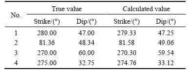
In order to verify the precision of the algorithm for calculating stratum structure attitude, four simulated structural lines on the unfolded image map are selected (as shown in Fig. 9) which represent four structural planes with different geological attitudes. The geological attitude measured on the unfolded image map is compared with the attitude directly measured on site; the result is listed in Table 2.
To facilitate the calculation, the geodetic azimuth presentation way (0��-360��) is adopted for the structural plane in Table 2. It can be learnt that algorithms in this paper can accurately realize the tunnel image orientation control, image projection correction, unfolded image map generation, etc. Furthermore, the geometric precision of the attitude measurement is sufficient tomeet the requirements of photographic geological logging in tunnels. Of course, the application precision will be slightly affected by the actual overbreak- underbreak in the tunnel engineering, but such impact will not change the above basic conclusions of the method in this work based on the engineering geological logging operation norm.
Table 2 Comparison between true attitude and calculated attitude
6 Conclusions
1) According to the particularity of small tunnels, a novel method of photographic geological logging is established, including image acquisition method, image orientation control method, image geometric correction method, unfolded image generation method, coordinate systems interconversion and stratum structure attitude measurement.
2) Through the experiment, it can be seen that the method can meet the precision requirements for geological logging for small tunnels.
3) The novel method of photographic geological logging can realize the fast acquisition and processing of geological logging information for small tunnels. Obviously, when compared with the traditional manual methods, the logging result forms are more abundant, and it is easier to realize informatized management and application of geological logging data.
References
[1] FENG Q J, JING L J, STEPHANSSON O J, VEJDE S J. A new approach for geological surveying of exposed rock faces [C]// Proceedings of the 2nd Asian Rock Mechanics Symposium. Beijing, China: International Society for Rock Mechanics, 2001: 619-622.
[2] ZHANG Z, KULATILAKE P H S W. A new stereo-analytical method for determination of removal blocks in discontinuous rock masses [J]. International Journal for Numerical & Analytical Methods in Geomechanics, 2003, 27(10): 791-811.
[3] Ye Ying, Wang Meng-shu. Geological information research at tunnel excavating face by image compiling and identify technology [J]. Journal of Beijing Jiaotong University, 2007, 31(1): 59-62. (in Chinese)
[4] FERRERO A M, FORLANI G, RONCELLA R, VOYAT H I. Advanced geostructural survey methods applied to rock mass characterization [J]. Rock Mechanics & Rock Engineering, 2009, 42(4): 631-665.
[5] Yakar M. Using close range photogrammetry to measure the position of inaccessible geological features [J]. Experimental Techniques, 2011, 35(1): 54-59.
[6] Wickens E H, Barton N R. The application of photogrammetry to the stability of excavated rock slopes [J]. Photogrammetric Reccord, 1971, 7(37): 46-54.
[7] Allam M M. The estimation of fractures and slope stability of rock faces using analytical photogrammetry [J]. Photogrammetria, 1978, 34(3): 89-99.
[8] OHNISHI Y, NISHIYAMA S, YANO T, MATSUYAMA H��AMANO K. A study of the application of digital photogrammetry to slope monitoring systems [J]. International Journal of Rock Mechanics & Mining Sciences, 2006, 43(5): 756-766.
[9] Di Crescenzo G, Santo A. High-resolution mapping of rock fall instability through the integration of photogrammetric, geomorphological and engineering-geological surveys [J]. Quatemary International, 2007, 171(4): 118-130.
[10] FRANCIONI M, SALVINI R, RICCUCCI S, GUASTALDI E, ORTOLANO F, BONCIANI F, CALLEGARI I, FANTOZZI P L. Rock fall trajectory modelling by the integration of digital terrestrial photogrammetry, laser scanning and GIS [C]// Proc EGU General Assembly Conference Abstracts. Vienna, Austria: EGU General Assembly, 2010, 12: 13900.
[11] SALVINI R, FRANCIONI M, RICCUCCI S, FANTOZZI P L, BONCIANI F, MANCINI S. Stability analysis of ��Grotta delle Felci�� Cliff (Capri Island, Italy): structural, engineering�Cgeological, photogrammetric surveys and laser scanning [J]. Bulletin of Engineering Geology & the Environment, 2011, 70(4): 549-557.
[12] FIRPO G, SALVINI R, FRANCIONI M, RANJITH P G. Use of digital terrestrial photgrammetry in rocky slope stability analysis by distinct elements numerical methods [J]. International Journal of Rock Mechanics & Mining Sciences, 2011, 48(7): 1045-1054.
[13] Zhang You-jing, Li Hao, Liu Xin-zhong. Technique study on fast log of photographic geology [J]. Hydrogeology and Engineering Geology, 2003, 30(3): 36-38. (in Chinese)
[14] Li Hao, Zhang You-jing, Hua Xi-sheng. Geologic logging of digital photos and its basic algorithm [J]. Editorial Board of Geomatics and Information Science of Wuhan University, 2004, 29(9): 805-808. (in Chinese)
[15] SONG Xiao-bing, CHEN You-hua, XUE Guo-fu, WANG Jia-xiang. Precise and visual geological compilation technology for large cavern measurement [J]. Construction Technology, 2013, 42(5): 298-301. (in Chinese)
[16] LI H, CAI Y, YANG B, WU M. A fast geological logging technique of underground coal mines based on photogrammetry [J]. Advanced Materials Research, 2013, 663: 661-667.
[17] Li H, ZHANG R, YANG B, WU M. Principle and geometric precision of photographic geological logging of tunnels [J]. Journal of Applied Remote Sensing, 2014, 8(1): 4480-4494.
[18] LINDER W. Digital photogrammetry-theory and applications [M]. Heidelberg: Springer, 2003.
[19] WANG Zhi-zhuo. Photogrammetry principle [M]. Wuhan: Wuhan University Press, 2007. (in Chinse)
[20] KRAUS K. Photogrammetry [M]. Berlin: De Gruyter, 2007.
(Edited by YANG Hua)
Foundation item: Project(201508) supported by the Open Research Foundation of Engineering Research Center for Rock-Soil Drilling & Excavation and Protection (Ministry of Education), China; Project(BK2012812) supported by the Natural Science Foundation of Jiangsu Province, China; Project(KYLX_0492) supported by the University Postgraduate Scientific Research and Innovation Project of Jiangsu Province, China; Project(2014B38714) supported by the Fundamental Research Funds for the Central Universities, China
Received date: 2015-05-26; Accepted date: 2015-11-15
Corresponding author: LI Hao, Professor, PhD; Tel: +86-25-83786961; E-mail: lihao@hhu.edu.cn
