J. Cent. South Univ. (2017) 24: 929-936
DOI: 10.1007/s11771-017-3495-8

Fire resistance performance of glulam beam
CHEN Chang-kun(�³���), YANG Jian(�), CHEN Jie(�½�), ZENG Jia-wei(����ΰ),
WANG Wei-yu(������), ZHAO Xiao-long(����)
Institute of Disaster Prevention Science and Safety Technology, Central South University, Changsha 410075, China
 Central South University Press and Springer-Verlag Berlin Heidelberg 2017
Abstract: A glulam beam with the size of 4700 mm��300 mm��480 mm (L��W��H) was tested in the furnace to investigate the fire resistance performance of glulam beam according to the temperature curve of ISO834. Three surfaces, the bottom and the two flanks, of the glulam beam were exposed to fire in the test. Simply supported bearings were used to support the beam on which the load of 0.76 kN/m was uniformly set. The experimental results show that: 1) Sectional dimension of glulam beam was greatly diminished due to the serious decomposition and carbonization of the timber. 2) The largest vertical deformation is relatively small and it has not exceeded 3.95 mm until the end of experiment. The maximum temperature on the top surface of the glulam beam attains 180 ��C at 3437 s, which indicates that the beam have failed according to the European standard of fire resistance tests. 3) The right end of the beam with 16 connecting holes (the connecting holes were used for the connection between bolt and column) and the slit in the beam both burnt intensely and carbonized seriously because the fire could reach the holes and slit of beam facilitating the burning.
Key words: glulam beam; experimental investigation; temperature; fire resistance; carbonization
1 Introduction
Glulam beam is the wood structure glued by the different thickness of wood along the grain direction. It is usually connected by the bolts, pins, hexagon screws, shear plate etc and the design reference period is generally 50 years [1, 2]. In recent years, the glulam timber structures have been popularly applied in historic building, landscape architecture, etc., throughout the world due to the advantages in energy conservation, environmental protection, excellent structural performance, etc [3-6]. However, the application of glulam timber has been greatly limited because of the high flammability, large amount of smoke and toxic gas during the combustion. Thus, research on the combustion characteristics of glulam timber (e.g., the fire resistance) is necessary and urgent for enlarging the application field of this kind of material.
Recently, research on the mechanical property of glulam beam has drawn the attention of many scholars. NAGHIPOUR et al [7] researched the natural frequency and dynamic responses of glued-laminated beams and obtained the periodic solutions and nonlinear analysis by the method of exp-function. VANESSA et al [8] conducted a series of experiments and numerical simulations to investigate the effect of self-tapping screws on moisture. SASAN et al [9] investigated the bending strength of the specially reinforced glued laminated timbers (glulam) with Glass fiber-reinforced plastic (GFRP). LU et al [10] conducted a series of experiments and numerical simulations to investigate the flexural behaviour of glulam beams reinforced. VINCENZO et al [11] conducted a series of four-point bending tests to research the flexural behavior of glulam timber beams. NICOLAS et al [12] conducted a new shear connection system test to estimate the mean load-carrying capacity and stiffness of the combined joint.
Research on the property of glulam beam under fire has also been conducted by some scholars. TOMI et al [13] analyzed the reliability of glulam beam under the condition of snow load and fire according to design procedures of Eurocode 5. SCHNABL et al [14] developed a transient moisture-thermal state of a timber beam model to simulate the behavior of timber composite beams when simultaneously exposed to static loading under fire. NUBISSIE et al [15] presented the variations of the failure time of a wooden beam in fire subjected to the combined effect of axial and transversal loads. MAXIME et al [16, 17] developed the thermo- mechanical models to research the temperatures and load-displacement curves of Steel-to-timber connections. JUKKA et al [18] presented a probabilistic simulation approach to assessment of the fire endurance of a wooden load-bearing beam in a fire. LI et al [19, 20] investigated the effects of microwave radiation intensity, radiation time and initial wood moisture content (MC) on the properties of temperature development in Eucalyptus urophylla wood samples during the microwave explosion pretreatment using a new microwave pretreatment equipment. SCHMID et al [21] researched the fire resistance tests of timber members in bending, tension and compression with respect to the reduced cross-section method. However, specific full-scale experimental studies on the mechanical property, pyrolysis property and fire resistance limit of glulam beam are relatively less, and further studies are necessary.
Experimental study on the fire resistance performance of glulam beam was conducted in this work. The results are considered beneficial for the development of scientific understanding and rational design methods for the glulam beam in fire.
2 Experimental
2.1 Requirements of European standard of fire resistance tests
The fire resistance test for glulam beam in this paper is based on the European standard of fire resistance tests requirements at the glulam beam and the requirements mainly includes load bearing capacity requirements, insulation requirements, and integrity requirements [22, 23].
1) Load bearing capacity requirements
The limiting deflection formula:
 (1)
(1)
where d is the thickness of the glulam beam and L represents the clear span between the two fulcrums. In this test, d is 460 mm and L is 4200 mm. Therefore, the limiting deflection D=95.87 mm.
2) Insulation requirements
The component is considered not meeting the insulation requirements once the temperature on the surface unexposed to fire achieves the either following two conditions:
(1) The average temperature above the surface unexposed to fire exceeds 140 ��C;
(2) The temperature above any location (including the roving thermocouple) of the surface unexposed to fire exceeds 180 ��C.
The initial average temperature shall be the average unexposed face temperature at the commencement of the test.
2.2 Size of glulam beam
The glulam beam with the size of 4700 mm��300 mm��480 mm (L��W��H) , as shown in Fig. 1, was tested in this experiment. Actually, the original length of the glulam beam was 5800 mm and the two ends of glulam beam were originally symmetrical, as shown in Fig. 1(b). However, the left end was sawed off in our test to make the measuring instrument used more efficiently and the one end could already reflect the fire resistance of the beam end.
There are 16 connecting holes and a slit with dimension of 1000 mm��20 mm��360 mm (L��W��H), as shown in Figs. 2(b) and (c), on the right beam end. The silt penetrates the beam along the centerline and the height turns to 120 mm at 1000 mm away from the end, as illustrated in Fig. 1(b) and Fig. 2(a).
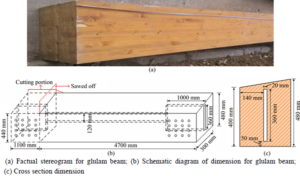
Fig. 1 Experimental specimen:
2.3 Loading and thermocouples arrangement
Figure 3 shows the pedestal arrangement for the glulam beam. Simply supported bearings, sliding bearings at left and fixed hinges at right were used in the experiment. Ten 5 kg-weights (50 kg) were manually put on beam to simulate uniform distribution load of 0.76 kN/m. Three displacement transducers were assembled at the top surface of the beam. In addition, temperature data were collected by 5 thermocouples, as shown in Fig. 4.
2.4 Test equipment
Three surfaces, the bottom and major part of the two flanks, of the glulam beam were exposed to fire. Asbestos and concrete were used to fill gaps between the two flanks and the furnace lid to protect the test equipment and improve the impermeability of furnace. The schematic diagram of the filling for glulam beam cross section and  are separately presented in Figs. 5(a) and (b). The top surface and the slit at the ends of beam were wrapped with asbestos. The gaps between two flanks and the furnace lid were filled with asbestos and concrete. The filler was 160 mm in depth, as shown in Fig. 5(a). Experimental diagram of the filling are shown in Fig. 6.
Horizontal furnace with the size of 4.8 m��3.6 m�� 1.8 m (L��W��H) was used in this test, as shown in Fig. 7. The fuel in the furnace was liquefied petroleum gas and the test temperature was conducted according to the standard temperature curve of ISO834.
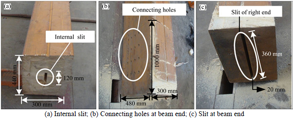
Fig. 2 Schematic illustration of glulam beam ends:
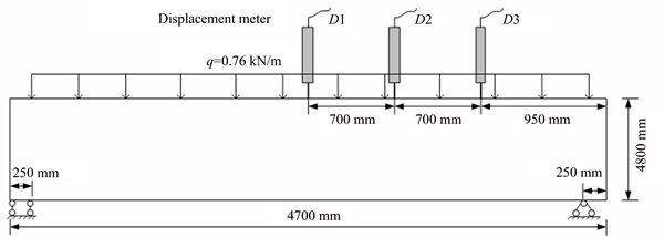
Fig. 3 Pedestal arrangement for glulam beam
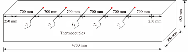
Fig. 4 Thermocouples arrangement
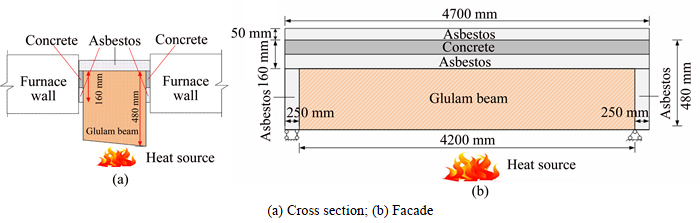
Fig. 5 Schematic diagrams of filling for glulam beam:
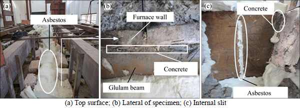
Fig. 6 Heat insulation for glulam beam:
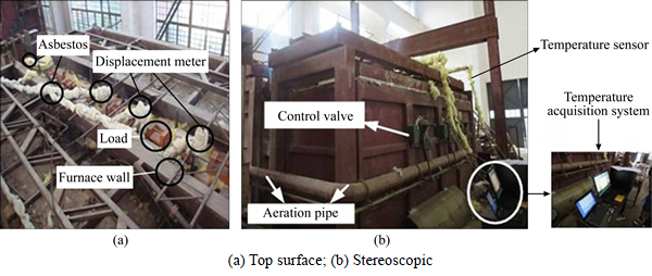
Fig. 7 Fire test horizontal furnace:
Figure 8 shows the temperature curve in the furnace, and it can be seen that the curve no longer follows the standard temperature curve (ISO834) after 3780 s. This is because the fire was relatively large and had spread to the top of furnace at this time. Temperature in the furnace then turns to decline due to the edge of the beam is burned through.
3 Results and discussion
3.1 Experimental data analysis
The temperature variation against time at the top surface of the beam is shown in Fig. 9. It can be seen that the temperature at T5 rises gradually as the time increases and it reaches to 180 ��C at 3437 s. It can be indicated that the fire resistance limit of the beam is 3437 s and it could not meet the European standard of fire resistance test at this moment. This is because the thermocouple T5 was set on the top surface of the right end of beam where 16 connecting holes and slit were located. The combustion there was more violent and the beam was burnt through at about 2000 s. Fire could then pass through the hole and reached the top surface of the beam leading to the temperature at T5 rising rapidly. Compared with the temperature curve at T5, the temperatures at T1-T4 are relatively stable after 2000 s. It can be indicated that the right end with the slit and 16 connecting holes are easier to be burnt than other parts of the beam in this test. The reason may be that some combustible gas gathered in the holes and the burning was facilitated.
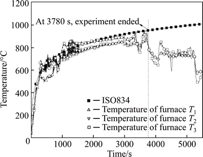
Fig. 8 Temperature curve in furnace compared with ISO834 curve
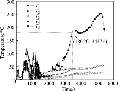
Fig. 9 Temperature curve at top surface of beam
Figure 10 shows the vertical displacement of the glulam beam during the test. It can be seen that the vertical displacements at these three measuring points of glulam beam all enlarges as the time increases. For these three measuring points, the vertical displacements at these three points are not obvious, as shown in Fig. 3, and the largest vertical displacements is only 3.95 mm, indicating that the stiffness and loadbearing capacity of the beam is relatively strong. Combining the phenomenon observed in the experiment that the glulam beam was not fractured during the fire, it can be indicated that the limiting deflection of loadbearing capacity could satisfy the requirement before the end of this experiment.
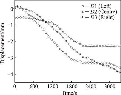
Fig. 10 Vertical displacement curve of top surface of glulam beam
3.2 Experimental phenomenon analysis
The ends of beam in fire at about 3437 s are presented in Figs. 11(a) and (b). It can be seen that even though both ends of the beam were wrapped with asbestos, the beam surface was decomposed and carbonized seriously during the test. What��s more, the right end burns more violently than the left because there are 16 connecting-holes at the right end where more combustible gases can gather to promote the burning. To observe the damage of beam after test, the ends of beam after burning are presented in Fig. 12. It can be seen that the left end of the beam carbonized seriously and a bighole appeared at the right end of the beam (with16 connecting-holes), as shown in Fig. 12(b). The phenomenon above indicates that the ends are the weakest part of the beam due to the exist of 16 connecting-holes and they are important parts needed to be researched for better understanding the fire resistance performance of the glulam beam.
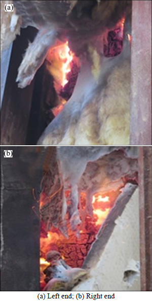
Fig. 11 Beam ends burnt acutely:
The top surface and bottom of the beam after burning are separately presented in Figs. 13(a) and (b). It can be seen that though the asbestos were used to prevent the top surface and flanks of beam from burning, the flanks and top surface carbonized obviously, as shown in Figs. 13(a). The bottom of beam also carbonized seriously, as shown in Fig. 13(b). The right end of the bottom was burnt through and appears a big hole. The main reason is the bottom of beam faced the high temperature flame straightly and there was a gap at the end originally, as shown in Fig. 2, where the flame could flow in and the burning area is then larger.
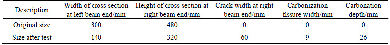
The size changes of glulam beam after the test are measured, as shown in Fig. 14, and the data are listed in Table 1. The results show that the right end of beam was badly damaged during the test: the height of the right end of beam reduced from 480 mm to 320 mm, the area of the connecting holes were burnt through, and a 60 mm width gap appeared; the width of the left beam end reduced from 300 mm to 140 mm, and the carbonization fissure and carbonation depth were about 9 mm and 26 mm, respectively. All the results indicate that a serious pyrolysis process occurred during the test.
In summary, the beam was seriously damaged during the test. Especially, the cross section of beam reduced significantly and the top surface of the beam was also partly burnt. Severe combustion and pyrolysis appeared during the test indicating that the fire resistance performance of glulam beam is poor. Thus, in order to broaden its applications in various fields, some heat insulation measures should be taken to improve the fire resistance performance of the glulam beam, especially for the gap and connecting holes at the end.

Fig.12 Beam end after test:
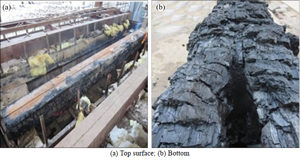
Fig. 13 Burnt specimens:
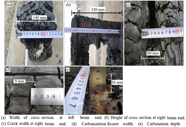
Fig. 14 Photos of measurement after test:
Table 1 Experimental measured data after test
4 Conclusions
1) The experimental results show that the beam end (with 360 mm width slit and 16 connecting holes) is the weakest position of the beam in the test of fire resistance performance. The main reason is that combustible gas could gather in the holes and the burning is then facilitated. The height of the right beam end reduced from 480 mm to 320 mm; the area of the connecting holes were burnt through, and a gap of 60 mm width appeared; the width of the left beam end reduced from 300 mm to 140 mm, and the carbonization fissure and carbonation depth were about 9 mm and 26 mm, respectively. All the results indicate that a serious pyrolysis process occurred during the test. Therefore, some heat insulation measures should be taken to improve the fire resistance performance of the beam.
2) It was observed that a severe pyrolysis and combustion occurred in the test and the cross section reduced obviously. Therefore, this kind of structure should be protected with the intumescent coatings or waterborne fire retardant for the purpose of better heat insulation.
3) The maximum temperature on the top surface of the glulam beam attains 180 ��C at 3437 s and the vertical deformation is only 3.95 mm. It can be indicated that the heat insulation of the beam could not meet the European standard of fire resistance tests, while the load bearing capacity could meet the standard.
4) It should be noted that the glulam beam in the experiment is used as connecting components with holes at the end and the size is 4700 mm��300 mm��480 mm (L��W��H). The conclusions raised based on the experiment may be not suitable for all glulam beams in the architecture field. But the test method and results can provide some valuable reference for the research of fire response characteristics of glulam beams. The connecting between glulam beam and column should be paid enough attention because the joints of the beam were easy to fail when being subjected to fire and this failure mode directly caused the beam collapse. The fire resistance performance of glulam beam could be influenced by the fire position, supporting system, fire prevention measures, etc. Further studies about the influence factors should be conducted in the future.
References
[1] GBT 50708-2012. Technical code of glued laminated timber structures [S]. (in Chinese)
[2] NI Zhao-peng, PENG Lei. Experimental study on fire resistance performance of timber assemblies [J]. China Civil Engineering Journal, 2012, 45(12): 108-114. (in Chinese)
[3] ANSHARI B, GUAN Z W, KITAMORI A, JUNG K, KOMATSU K. Structural behaviour of glued laminated timber beams prestressed by compressed wood [J]. Construction and Building Materials, 2012, 29(4): 24-32.
[4] NADIR Y, NAGARAJAN P. The behavior of horizontally glued laminated beams using rubber wood [J]. Construction and Building Materials, 2014, 55(2): 398-405.
[5] ALVAREZ A, MEACHAM B, DEMBSEY N. Twenty years of performance-based fire protection design: Challenges faced and a look ahead [J]. Journal of Fire Protection Engineering, 2013, 23(4): 249-276.
[6] EZEKOYE O A, ANDERSON A. A comparative study assessing factors that influence home fire casualties and fatalities using state fire incident data [J]. Journal of Fire Protection Engineering, 2013, 23(1): 51-75.
[7] NAGHIPOUR M, HASHEMI K S. Periodic solutions and nonlinear analysis used for evaluating of dynamic properties of glued- laminated beams reinforced with GRP [J]. Journal of Applied Mechanics, 2011, 78(1): 2054-2060.
[8] ANGST V, ARNE M K. Effect of self-tapping screws on moisture induced stresses in glulam [J]. Engineering Structures, 2012, 45(2284): 299-306.
[9] OSMANNEZHAD S, FAEZIPOUR M, EBRAHIMI G. Effects of GFRP on bending strength of glulam made of poplar (Populus deltoids) and beech (Fagus orientalis) [J]. Construction and Building Materials, 2014, 51(2): 34-39.
[10] LU Wei-dong, LING Zhi-bin. Study on flexural behaviour of glulam beams reinforced by Near Surface Mounted (NSM) CFRP laminates [J]. Construction and Building Materials, 2015, 91(5): 23-31.
[11] LUCA V D, MARANO C. Prestressed glulam timbers reinforced with steel bars [J]. Construction and Building Materials, 2012, 30(5): 206-217.
[12] JACQUIER N, GIRHAMMAR U A. Tests on glulam�CCLT shear connections with double-sided punched metal plate fasteners and inclined screws [J]. Construction and Building Materials, 2014, 72: 444-457.
[13] TORATTI T, SCHNABL S. Reliability analysis of a glulam beam [J]. Structural Safety, 2007, 29(4): 279-293.
[14] SCHNABL S, PLANINC I. Fire analysis of timber composite beams with interlayer slip [J]. Fire Safety Journal, 2009, 44(5): 770-778.
[15] NUBISSIE A, TALLA E K, WOAFO P. Effects of the combined action of axial and transversal loads on the failure time of a wooden beam under fire [J]. Materials and Design, 2012, 40: 331-335.
[16] AUDEBERT M, DHIMA D. Experimental and numerical analysis of timber connections in tension perpendicular to grain in fire [J]. Fire Safety Journal, 2014, 63(1): 125-137.
[17] SAMAKE A, TAAZOUNT M. Thermo-hydric transfer within timber connections under fire exposure: Experimental and numerical investigations [J]. Applied Thermal Engineering, 2014, 63(1): 254-265.
[18] HIETANIEMI J. Probabilistic simulation of fire endurance of a wooden beam [J]. Structural Safety, 2007, 29(4): 322-336.
[19] LI Xian-jun, LU Ke-yang. Fundamental characteristics of microwave explosion pretreatment of wood. I. Properties of temperature development [J]. Forestry Studies in China, 2010, 12(1): 9-13.
[20] CHEN Chang-kun, ZHANG Wei. Structural behaviors of steel roof truss exposed to pool fire [J]. Journal of Central South University, 2012, 19(7): 2054-2060.
[21] SCHMID J, KLIPPEL M. Review and analysis of fire resistance tests of timber members in bending, tension and compression with respect to the Reduced Cross-Section Method [J]. Fire Safety Journal, 2014, 68(7): 81-99.
[22] BS EN 1363-1:1999. Fire resistance tests-Part 1: General requirements [S].
[23] PAGE A. Eurocode 5: Design of timber structures. W 1995, Part 1-2: General rules-Structural fire design [J]. European Committee for Standardization, 1994, 144(11): 39-43.
(Edited by YANG Bing)
Cite this article as: CHEN Chang-kun, YANG Jian, CHEN Jie, ZENG Jia-wei, WANG Wei-yu, ZHAO Xiao-long. Experimental investigation on fire resistance performance of glulam beam [J]. Journal of Central South University, 2017, 24(4): 929-936. DOI: 10.1007/s11771-017-3495-8.
Foundation item: Projects(51576212, 51534008) supported by the National Natural Science Foundation of China; Project(2016YFC0802501) supported by the National Key Research and Development Program of China; Project(KFKT2014ZD02) supported by the Open Fund of Key Laboratory of Building Fire Protection Engineering and Technology of Ministry of Public Security, China
Received date: 2015-07-24; Accepted date: 2015-12-09
Corresponding author: CHEN Chang-kun, Professor, PhD; Tel: +86-731-82656625; E-mail: cckchen@csu.edu.cn

