Trans. Nonferrous Met. Soc. China 22(2012) s254-s260
Development of thermal deep drawing system with vacuum environment for difficult-to-deformation materials
MENG Bao, WAN Min, WU Xiang-dong, ZHOU Ying-ke
School of Mechanical Engineering and Automation, Beihang University, Beijing 100191, China
Received 28 August 2012; accepted 25 October 2012
Abstract: The thermal deep drawing process with vacuum environment was put forward to solve the problems in the forming of the high strength and difficult-to-deformation sheet metals such as difficult to form under normal temperature and easily to be oxidized at high temperatures. The vacuum hot drawing system was discussed and developed based on the integration of vacuum heating technology and variable blank holding force (BHF) system, which consisted of mainframe system, hydraulic system, vacuum system, heating system, water-cooling system, air-cooling system and computer control system, and the key parameters such as temperature, BHF and punch velocity were regulated in real time using PID closed-loop control technique. The deep drawing test of 2.0 mm-thick molybdenum sheets with temperature of 870 ��C and vacuum degree of 10-2 Pa was conducted on the system, and the molybdenum crucible with limiting drawing ratio of 1.94 was obtained, which indicated that the vacuum thermal drawing technology provided an effective solution for the formability improvement of difficult-to-deformation materials with strictly protecting against oxidation.
Key words: molybdenum sheet; thermal deep drawing; vacuum environment; variable blank holding force; system design; difficult-to-deformation materials; computer numerical control; drawing test
1 Introduction
The increasing severity of energy sources and environment issues emerged and the new legislations for controlling the pollution and saving energy have forced the demand of weight lightening within the aerospace and automotive industries in recent years [1,2]. Owing to the high specific stiffness and strength, excellent fatigue resistance, good corrosion resistance and recycling potential, the light alloys, such as aluminum alloy [3,4], titanium alloy [5], magnesium alloy [6,7] and ultrahigh strength steel sheets [8], have become the ideal candidates to replace the heavier materials to respond to the weight reduction. Also, the use of light alloys for biomedical and dental applications has increased considerably due to their good biocompatibility [9,10].
Unfortunately, the deep drawability of the proposed difficult-to-deformation materials was very poor at room temperature, which had limited their further applications [11]. However, the plasticity of the difficult-to- deformation materials was gradually strengthened, and the deformation resistance decreased with the increase of temperature, and the formability was significantly improved [12,13]. Many efforts had made to investigate the high-temperature behavior of difficult-to-deformation materials, and the method with heating apparatus placed on die tools had been widely applied to obtaining the thermal environment [14,15]. However, the disadvantages, such as low heating capacity, poor temperature uniformity and hard to manipulate, limited its application. Then the specialized hot deep drawing equipment had been proposed to replace the heating apparatus, which generally added a furnace to the ordinary hydraulic press without considering the vacuum environment because it was difficult to realize vacuum conditions at high temperatures with the movements of the punch and blank holder, and the workpieces had often been oxidized seriously. In addition, such equipment could not realize the dynamic regulation of BHF, which could improve the forming properties obviously [3,16].
The major goal of this work is to develop the thermal deep drawing system with vacuum environment and variable blank holder force for investigating the high-temperature forming behavior of difficult-to-deformation materials. To verify the practicability and reliability of the system, the deep drawing experiments of molybdenum sheets were conducted.
2 Overall technical plan and approach
The maximum design temperature is 950 ��C, and the corresponding vacuum degree is 10-2 Pa, which can suit for thermal drawing of the most metal materials commonly used at present. The system shown in Fig. 1 contains seven subsystems including mainframe system, hydraulic system, heating system, vacuum system, air-cooling system, water-cooling system and computer control system, among which, the mainframe system consists of a double-action hydraulic press, resistance furnace and the die holder, and the forming force (maximum 500 kN), punch velocity (from 2 mm/min to 200 mm/min) and BHF (form 0 to 300 kN) were measured in real time by corresponding sensors. Hydraulic system regulated BHF and punch velocity with instructs of computer control system through proportional valves of BOSCH company. Vacuum system extracted the air in the furnace using mechanical pump and diffusion pump, and water-cooling system refrigerated furnace body, heating electrodes, heat exchanger and diffusion pump by air-to-water chiller, while air-cooling system circulated the inert gases filled in advance between the furnace and heat exchanger to accelerate the rate of heat exchange when the drawing process had been completed. Heating system heated the dies and workpiece through the resistance wires, and the temperature was adjusted by the intelligent controller automatically.
Control mode based on upper computer using industrial personal computer (IPC) and lower computer with programmable logic controller (PLC) was put to use, and IPC was communicated with PLC through Ethernet, which enabled remote monitoring and data storage with the high stability and reliability in a variety of environmental conditions. Moreover, the man-machine interface of upper computer had features of convenient operation and easy to add new functions.
3 Design and practice
The normal operation of the system is mainly decided by the practice of vacuum system, thermal environment and cooling system, while the control accuracy and system functions are mainly determined by the computer control system.
3.1 Vacuum system
The vacuum system shown in Fig. 2 mainly consisted of mechanical pump, diffusion pump, vacuum valves and vacuometers. There were two channels to pump the air outside the furnace named low vacuum (105-100 Pa) and high vacuum (10-1-10-3 Pa). The mechanical pump, differential valve and forvacuum valve were used in the coarse vacuum, and the measuring cell was Priani gauge with measuring range from 105 to 10-1 Pa , while diffusion pump, pre-stage valve and baffle valve were applied to high vacuum, and the corresponding measuring element was ionization gauge in the range of 10-1-10-5 Pa.

Fig. 1 Schemic diagram of vacuum thermal deep drawing system

Fig. 2 Design of vacuum system
The features of high pumping speed for all gases and low cost per unit pumping speed made the diffusion pump attractive for high vacuum uses. However, diffusion pump could not discharge directly into the atmosphere, so a mechanical forepump was typically used to maintain an outlet pressure (less than 10 Pa). The high speed jet was generated by boiling the oil in the diffusion pump and directing the vapor through a jet assembly, while the outside of diffusion pump was cooled by the cooling water. Namely, the forepump and water-cooling system were essential to the normal operation of diffusion pump.
3.2 Heating system
The heating system illustrated in Fig. 3 heated the die tools and workpiece in the furnace by controlling the current, which were energized with delta connection. The automatic temperature control was realized using thermostat and temperature sensors, which transferred the control signal to the power controllers for regulating the current. Furthermore, two additional thermocouples were placed in the different regions in the furnace to improve the temperature uniformity, and the thermocouple measuring temperature of the workpiece was designed as a removable unit to contact the workpiece for accurate measurement.
3.3 Water-cooling system
The water-cooling system shown in Fig. 4(a) was absolutely crucial to the steady operation of the whole system, and the furnace, electrodes, diffusion pump and pipelines were cooled independently by the air-to-water chiller consisting of indoor and outdoor units. In addition, a water segregator was designed for the independent cooling.
To avoid the blind area around the corner of the furnace body, the baffles illustrated in Fig. 4(b) were welded on the inner wall to lead the cooling water spiraling up along the thin plates, which increased the area of heat exchange between the cooling water and the furnace body, and the direction of cooling water was forced to flow from bottom to top. In addition, a temperature detection device was set at the exit of the water segregator to monitor the temperature of the outlet, and the water pressure monitoring unit was placed at the entrance, the heating system and vacuum system would be forced to stop, and the alarm sound was sent to remind users if the temperature of outlet water exceeded 40 ��C or the pressure of inlet water was less than 0.1 MPa. The volume flow rate of cooling water can be expressed as
 (1)
(1)
where v is the volume flow rate; N is the consumptive power induced by the loss heat taken away by the cooling water; c is the volume specific heat of water; t2 is the temperature of outlet water; t1 is the temperature of inlet water. The equivalent diameter of water pipe can be estimated as
 (2)
(2)
where d is the equivalent diameter of cooling water pipe; w is the economical velocity of water with common range from 0.8 to 1.6 m/s.

Fig. 3 Schematic chart of heating system

Fig. 4 Design of water-cooling system
3.4 Air-cooling system
Many experiments had indicated that the cooling rate slowed down as the temperature decreased naturally under vacuum environment, especially, when the temperature fell to 500 ��C, the rate was less than 1 ��C/min, and about 6 h was needed to cool from 900 ��C to 200 ��C naturally, as shown in Fig. 5. The air-cooling system shown in Fig. 6 was added for rapid cooling of die tools and workpiece after the drawing process, which mainly contained high-pressure blower and heat exchanger.
As the inner temperature was inferior to 500 ��C, the protective gas was filled into the furnace until the pressure reaching 104 Pa, and then the blower and the corresponding valves were started to circle the gas between the heat exchanger and the furnace, while the heat was taken away by the cooling water when the heated gas flowed through copper tubes in the exchanger. The helical flow of cooling water leaded by the screw-guide plate, along with copper tubes with fins outside in the heat exchanger increased the efficiency of heat transfer and avoided the dead corner of heat exchange.

Fig. 5 Comparison of cooling rate between natural cooling and air-cooling system

Fig. 6 Principle of air-cooling system
It can be seen from Fig. 5 that when the protective gas at room temperature was filled in furnace at 500 ��C, the space temperature was lowered rapidly because of the heat exchange between the gas and furnace, and then the air-cooling system accelerated the cooling rate from 1 ��C/min to 6 ��C/min, which shortened the cooling time obviously.
3.5 Computer control system
The forming accuracy and operability were directly determined by the computer control system. The control method based on upper and lower computers shown in Fig. 7 was put to use with Ethernet communication.
The lower computer system mainly contained compound vacuometer, intelligent temperature controller and Siemens S7-300 PLC, in which, vacuometer realized the wide measuring range with intelligent switching between pirani gauge and ionization gauge, and the temperature controller implemented the closed loop control and the record of temperature, while PLC was primarily responsible for logic output and data acquisition such as punch stroke, BHF and forming force.

Fig. 7 Principle of computer control system
4 Application of system
In order to validate the reliability of the vacuum thermal drawing system, the cup-drawing test for 2.0 mm-thick molybdenum sheets was designed and conducted on the system proposed in Fig. 8, and the die tools with constant clearance between the die and binder were designed as shown in Fig. 9.

Fig. 8 Thermal deep drawing system developed with vacuum environment

Fig. 9 Die tools for experiments
To the best of our knowledge, molybdenum sheet was oxygenized easily at high temperatures in the air, and its deep-drawing process was always a bottle-neck because of the poor plasticity under the normal temperature. The experiments were carried out to investigate the limiting drawing ratio of molybdenum sheet at 870 ��C with the high-vacuum environment protecting the sheet from being oxidized, and the limiting drawing ratio (LDR) is defined as
 (3)
(3)
where dp is the punch diameter; D0 is the diameter of the blank, which was designed from 91 mm to 100 mm. The experimental conditions are shown in Table 1.
Table 1 Experimental conditions

The test parts are shown in Fig. 10(a), and the drawing force with respect to the punch travel is depicted in Fig. 10(b). The ruptures appeared when D0 was equal to 100 mm with the maximum drawing force 62.5 kN, and the LDR of molybdenum sheet at 870 ��C was 1.94.
It can be seen that the parts were drawn by vacuum thermal drawing system without oxidized particles, and the drawing force decreased significantly compared with cold stamping, which shows that the system introduced into the manufacturing of difficult-to-deformation materials has broad prospects.
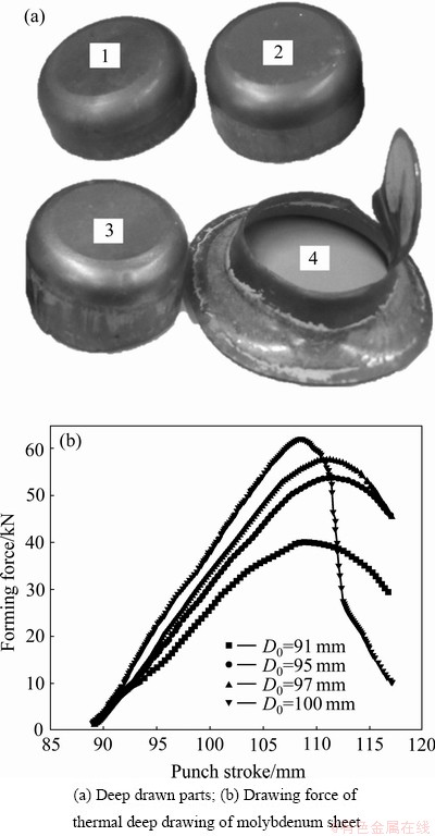
Fig. 10 Test results
5 Conclusions
1) Hot deep drawing of difficult-to-deformation materials applying vacuum environment protects the deep drawn parts from oxidizing effectively.
2) The accurate regulation and control of punch velocity and BHF under the vacuum thermal condition improves the forming precision, and enlarges the application range of the hot drawing process.
3) Natural cooling rate reduces to about 1 ��C/min when the temperature falls to below 500 ��C, and the air-cooling subsystem accelerates the cooling speed to 6 ��C/min.
4) The experiments conducted on the system realize the thermal cup-drawing test of molybdenum sheet under the condition of temperature 870 ��C and vacuum degree 10-2 Pa, and the corresponding limiting drawing ratio is 1.94.
References
[1] COLE G S, SHERMAN A M. Light weight materials for automotive applications [J]. Materials Characterization, 1995, 35(1): 3-9.
[2] LIU J, TAN M J, JARFORS A, AUE-U-LAN Y, CASTAGNE S. Formability in AA5083 and AA6061 alloys for light weight applications [J]. Materials & Design, 2010, 31(1): 66-70.
[3] WANG W R, CHEN G L, LIN Z Q. Application of new VBHF optimization strategy to improve formability of automobile panels with aluminum alloy sheet [J]. Transactions of Nonferrous Metals Society of China, 2010, 20(3): 471-477.
[4] HEINZ A, HASZLER A, KEIDEL C, MOLDENHAUER C, BENEDICTUS R, MILLER W S. Recent development in aluminium alloys for aerospace applications [J]. Materials Science and Engineering A, 2000, 280(1): 102-107.
[5] JHA A K, SINGH S K, KIRANMAYEE M S, SREEKUMAR K, SINHA P P. Failure analysis of titanium alloy (Ti6Al4V) fastener used in aerospace application [J]. Engineering Failure Analysis, 2010, 17(6): 1457-1465.
[6] ALAM M E, HAN S, NGUYEN Q B, SALEM HAMOUDA A M, GUPAT M. Development of new magnesium based alloys and their nanocomposites [J]. Journal of Alloys and Compounds, 2011, 509(34): 8522-8529.
[7] LIN B T, KUO C C. Application of an integrated RE/RP/ CAD/CAE/CAM system for magnesium alloy shell of mobile phone [J]. Journal of Materials Processing Technology, 2009, 209(6): 2818-2830.
[8] WANG X D, GUO Z H, RONG Y H. Mechanism exploration of an ultrahigh strength steel by quenching�Cpartitioning�Ctempering process [J]. Materials Science and Engineering A, 2011, 529: 35-40.
[9] YANG J X, CUI F Z, LEE I S, WANG X M. Plasma surface modification of magnesium alloy for biomedical [J]. Surface and Coatings Technology, 2010, 205: 182-187.
[10] KOIKE M, MARTINEZ K, GUO L, CHAHINE G, KOVACEVIC R, OKABE T. Evaluation of titanium alloy fabricated using electron beam melting system for dental [J]. Journal of Materials Processing Technology, 2011, 211(8): 1400-1408.
[11] ZHANG X H, TANG B, ZHANG X L, KOU H C, LI J S, ZHOU L. Microstructure and texture of commercially pure titanium in cold deep drawing [J]. Transactions of Nonferrous Metals Society of China, 2012, 22(3): 496-502.
[12] WEISS I, SEMIATIN S L. Thermomechanical processing of beta titanium alloys��An overview [J]. Materials Science and Engineering A, 1998, 243: 46-65.
[13] WANG H, LUO Y B, FRIEDMAN P, CHEN M H, GAO L. Warm forming behavior of high strength aluminum alloy AA7075 [J]. Transactions of Nonferrous Metals Society of China, 2012, 22(1): 1-7.
[14] WATARI H, KOGA N, DAVEY K, HAGA T, AIONSO RAGADO M T. Warm deep drawing of wrought magnesium alloy sheets produced by semi-solid roll strip-casting process [J]. International Journal of Machine Tools and Manufacture, 2006, 46(11): 1233-1237.
[15] MORI K, MAKI S, TANAKA Y. Warm and hot stamping of ultra high tensile strength steel sheets using resistance heating [J]. CIRP Annals-Manufacturing Technology, 2005, 54(1): 209-212.
[16] RAJU S, GANESAN G, KARTHIKEYAN R. Influence of variables in deep drawing of AA 6061 sheet [J]. Transactions of Nonferrous Metals Society of China, 2010, 20(10): 1856-1862.
�ѱ��β�����ջ���������ϵͳ�Ŀ�����Ӧ��
�� ������ ����������Ӧ��
�������պ����ѧ ��е���̼��Զ���ѧԺ������ 100191
ժ Ҫ��Ϊ����ѱ��β��ϳ��ι����г����ѳ��Ρ����������������⣬�����ջ����������������ռ��ȼ����ͱ�ѹ����������Ļ����ϣ���������ѱ��β��ϵ����������ϵͳ����ϵͳ������ϵͳ��Һѹϵͳ�����ϵͳ������ϵͳ��ˮ��ϵͳ������ϵͳ�ͼ�����Զ�����ϵͳ��ɣ���ͨ���ջ����Ƽ���ʵʱ�����¶ȡ�ѹ������ģ�ٶȵȹؼ����ղ��������¶�870 ��C����ն�10-2 Pa�������½���2.0 mm��������������飬�õ�����ڸ������µļ��������Ϊ1.94�������������ջ������������һ������ѱ��β��ϳ������ܺͷ�ֹ������������Ч������
�ؼ��ʣ���壻�������ջ�������ѹ������ϵͳ��ƣ��ѱ��β��ϣ����������ϵͳ����������
(Edited by LI Xiang-qun)
Corresponding author: WAN Min; Tel/Fax: +86-10-82338788; E-mail: mwan@buaa.edu.cn
DOI: 10.1016/S1003-6326(12)61716-6

