
J. Cent. South Univ. (2018) 25: 2944-2952
DOI: https://doi.org/10.1007/s11771-018-3964-8

Numerical simulation of hydraulic fracture propagation in weakly consolidated sandstone reservoirs
LIN Hai(林海)1, 2, DENG Jin-gen(邓金根)1, LIU Wei(刘伟)1,XIE Tao(谢涛)2, XU Jie(许杰)2, LIU Hai-long(刘海龙)2
1. State Key Laboratory of Petroleum Resources and Prospecting, China University of Petroleum,Beijing 102249, China;
2. State Key Laboratory Offshore Oil Exploitation, China National Offshore Oil CorporationChina Limited, Tianjin Branch, Tianjin 300459, China
 Central South University Press and Springer-Verlag GmbH Germany, part of Springer Nature 2018
Abstract: Frac-packing technology has been introduced to improve the development effect of weakly consolidated sandstone. It has double effects on increasing production and sand control. However, determining operation parameters of frac-packing is the key factor due to the particularity of weakly consolidated sandstone. In order to study the mechanisms of hydraulic fracture propagation and reveal the effect of fracturing parameters on fracture morphology in weakly consolidated sandstone, finite element numerical model of fluid-solid coupling is established to carry out numerical simulation to analyze influences of mechanical characteristics, formation permeability, fracturing fluid injection rate and viscosity on fracture propagation. The result shows that lower elastic modulus is favorable for inducing short and wide fractures and controls the fracture length while Poisson ratio has almost no effect. Large injection rate and high viscosity of fracturing fluid are advantageous to fracture initiation and propagation. Suitable fractures are produced when the injection rate is approximate to 3–4 m3/min and fluid viscosity is over 100 mPa·s. The leak-off of fracturing fluid to formation is rising with the increase of formation permeability, which is adverse to fracture propagation. The work provides theoretical reference to determine the construction parameters for the frac-packing design in weakly consolidated reservoirs.
Key words: weakly-consolidated sandstone; frac-packing; hydraulic fracture; fracture propagation; numerical simulation
Cite this article as: LIN Hai, DENG Jin-gen, LIU Wei, XIE Tao, XU Jie, LIU Hai-long. Numerical simulation of hydraulic fracture propagation in weakly consolidated sandstone reservoirs [J]. Journal of Central South University, 2018, 25(12): 2944–2952. DOI: https://doi.org/10.1007/s11771-018-3964-8.
1 Introduction
Frac-gravel packing completion technology is aiming at medium and high permeability reservoirs [1, 2]. It has been an effective measure to reduce sand production and increase the yield of reservoirs. Frac-packing combines the tip screening out (TSO) with gravel packing. It makes sand-carrying fluid form sand plug at the tip of fracture, which will prevent the fractures from continuous propagation.
The concept of compound frac-gravel pack completion firstly was put forward by GRUBERT [3]. The processes of frac-gravel pack can be divided into TSO and the expansion and packing sand of fractures [4]. SZ36-1oilfield introduced frac-gravel packing completion technology in 2006, however, SZ36-1 oilfield faces some problems after many years of water-flooding development, such as uneven displacement between layers. The water- flooded degree varies greatly from layer to layer, and the distribution of remaining oil is complex. The frac-gravel pack completion technology has achieved good application effect, but hydraulic fracturing design still mainly depends on experience. The mechanisms of fracture initiation and propagation in weakly-consolidated sandstone have always been a difficult point. The influence of fracturing operation parameters on the initiation and propagation of cracks, and oil and water migration after hydraulic fracturing is still not clear.
The fracture initiation and propagation of hard rocks have been extensively studied for many years, but some classic linear elastic and brittle fracture mechanics models suitable for hard rock are not applicable to weakly-consolidated sandstone [5, 6]. They cannot adequately describe fracture initiation in soft rocks. Some laboratory experiments have been done to identify the mechanisms initiation and propagation in soft rocks. KHODAVERDIAN et al [7] demonstrated that the propagation of fracture tip was mainly controlled by the regional fluid invasion of fracture tip and shear failure based on experiments. CHANG [8] found that all particles of weakly-consolidated sandstones were squeezed in the process of fracturing fluid injected to reservoir. DONG et al [9] found that fracture initiation and propagation in high permeability loose rocks are mainly affected by the fluid rheology and leak-off through laboratory experiments. To a large extent, fluid leak-off around fractures cause shear yield in the formation of fracture tip. GERMANOVICH et al [10] found in-situ stress is the main factor to control the injection pressure peak. High velocity, low leak-off and high viscosity are conducive to the generation of fracture. Some researchers [11, 12] have done some physical experiments to study the failure modes of weakly-consolidated sandstones, and they think the fracture is predominantly controlled by tensile failure at low confining stress, and it has the possibility of turning into shear failure in the process of propagation. In addition to the experimental studies, some researchers also have attempted numerical simulation methods to reveal the mechanisms of fractures in weakly- consolidated sandstones. Discrete element method (DEM) first proposed in 1971 by Dr. Cundall is specially used for the numerical simulation to solve the problem of discontinuous medium. The method considers rock as a kind of discontinuous discrete medium. MANCHANDA et al [13] simulated solid particles and pore fracture distribution of the loose sandstone by PFC3, which got the permeability evolution law of loose sand under different confining pressure. But the failure of loose sandstone is rarely studied by using the method. It is still in the exploratory stage. Weakly- consolidated sandstone has the characteristics of shallow buried depth, weak compaction, high pore and high permeability, poor cementation. It has a certain difference of the failure mechanisms between weakly-consolidated and consolidation sandstones because of the difference of mechanical and physical properties. The characteristics of rock deformation and failure in the process of hydraulic fracturing are different from traditional brittle and linear elastic rocks. At present, most traditional models of fracture initiation and propagation in soft sand are based on the theory of linear elastic mechanics, such as tensile fracture model, PKN model, KGD model, P3D model [14–17]. Traditional fracturing software is not applicable to analyze the fracture initiation and propagation in loose sand. ABAQUS was used to make finite numerical simulation to explore the regularity of hydraulic fracturing in hard rocks based on discrete element simulation to a certain extent, which reflects the characteristics of fracture propagation [18–20]. This work uses ABAQUS finite element software to reveal the rules of fracture initiation and propagation in weakly consolidated sandstone. The model is discretized by linear two-dimensional CPE4P element structured grid partition method and the propagation path of fractures is predefined by a nonlinear two-dimensional cohesive element. Meanwhile, the characteristics of plastic deformation for weakly-consolidated sandstone have been analyzed adopting modified Cam-Clay Model. The numerical calculation model of fracture propagation aiming at weakly-consolidated sandstone is established, which has been applied to optimize the design of frac-gravel packing completion for SZ36-1 oilfield in China, and obtained good practical effects.
2 Numerical simulation of fracture propagation for weakly consolidated sand fracturing
In order to investigate the influences of rock property and fracturing parameters on the fracture morphology of unconsolidated sand in the process of frac-gravel pack completion. Finite element method is used for numerical simulation. Based on the principle of damage mechanics, cohesive element adopts stiffness attenuation method to simulate the fracture initiation and propagation in medium.
2.1 Damage model of cohesive element
Damage mode of cohesive element is in accordance with traction–separation law [21, 22]. The bear stress of cohesive element is considered as damage criterion, as shown in Figure 1. When displacement jump is between 0 and d0 (the displacement of initiation damage for cohesive element), the deformation of cohesive element is described as elastic stage. Namely, the relationship between stress and displacement is linear dependent. When stress reaches tensile strength Tmax, the stress will decrease with the increase of the displacement. Finally, the stress becomes 0 when the displacement reaches df. It means that the materials are completely destroyed.
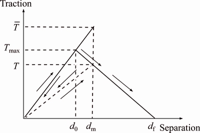
Figure 1 Traction–separation law of cohesive element
2.2 Initiation and propagation criterion of cohesive element
Quadratic nominal stress criterion is adopted as the fracture initiation criterion of cohesive element. It can be expressed as [23, 24]:
 (1)
(1)
where tn, ts and tt are the nominal tractions (Pa) in the normal and two local shear directions, respectively; is the peak value of the nominal stress (Pa) (tensile strength) in the traction– separation constitutive relationship of pore pressure cohesive element;
 and
and are peak values (shear strength) of the nominal stress (Pa) in the first and second shear direction, respectively.
 is the Macaulay bracket, with
 (2)
(2)
Cohesive element uses stiffness degradation to describe the damage process. It is expressed as:
 (3)
(3)
where  is the initial stiffness, GPa/m; K is the actual siffness, GPa/m; D is the damage facor.
Damage factor can be written as:
 (4)
(4)
where df, dm and d0 are the displacement (m) when element is completely destroyed, the maximum displacement in the loading process, and the displacement of initial damage, respectively.
2.3 Fluid flow within cohesive elements
The fluid flow in the cohesive element is divided into two parts. One part is the tangential flow along the cohesive element, and the other part is the normal flow on top and bottom surfaces perpendicular to cohesive element. Figure 2 shows the sketch of fluid flow within the cohesive elements.
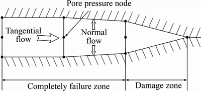
Figure 2 Sketch offluid flow within cohesive elements
Tangential flow is often viewed as incompressible Newtonian fluid and power-law flow. The paper adopts incompressible Newtonian fluid to represent the fluid flow in the characterization. Its calculating formula for tangential flow can be expressed as:
 (5)
(5)
where w is the fracture width, m; p is fluid pressure within the fracture, Pa; qt and qb are the leakoff rates (m3/min) at the two fracture faces, respectively.
Normal flow across the cohesive element surface is defined as:
 (6)
(6)
where qt and qb are the leakoff rates (m3/min) at the two fracture faces, respectively; ct and cb are the leakoff coefficents (m3/min) on the top and bottom surfaces of cohesive element, respectively; pi is the mid-node pressure (Pa) of cohesive element; pt and pb are the pore pressure (Pa) on the top and bottom surfaces of cohesive element, respectively.
2.4 Calculation model and results
Figure 3 shows the sketch of calculation geometry model. The size of caculation area is 100 m×100 m. The displacement on the top and bottom boundary of Y direction is constrained. The left boundary for X is symmetry boundary condition. The displacement on right boundary of X direction is constrained.
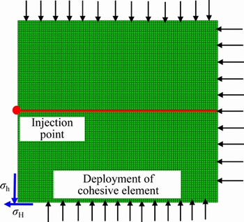
Figure 3 Sketch of calculation geometry model
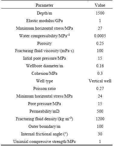
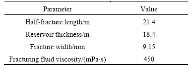
Because of the particular characteristics of weakly-consolidated sandstone, this work adopts modified Cam-Clay model as constitutive model to analyze its stress–strain relationship. Table 1 lists the model parameters.
According to the established numerical model, the effects of geologic factors and engineering factors on fracture height and fracture propagation of weakly-consolidated sandstone are studied. The mechanical properties studied are mainly elastic modulus (E) and Poisson ratio (v). Figure 4(a) indicates that the higher rock elastic modulus, the higher HF length along the direction of fracturing position, but the less HF width in the adjacent layer of reservoir. The result shows that the normal displacement of fracture surface is smaller in high elastic modulus of the barrier. The fracture geometry becomes flat and long. Figure 4(b) indicates the Poisson ratio nearly has no effect on HF length growth, and the HF eventually breaks through the barriers. The final HF geometries have almost little difference.
Table 1 Model parameters
Weakly consolidated sand has high permeability, its effects on the fracture geometry are studied. The permeability of reservoir is changed to 10, 100, 500 and 1000 mD, respectively, and other parameters are taken from Table 1. The fracturing fluid injection rate is 3 m3/min. Figure 5 shows that the fractures are hardly to propagate when the formation permeability is higher than 1000 mD. The smaller the formation permeability is, the easier the fracture propagates. The effective area of fracture induced by fracturing operation is becoming smaller and the leak-off of fracturing fluid to the formation is increased with the increase of formation permeability, which is disadvantaged to fracture propagation.
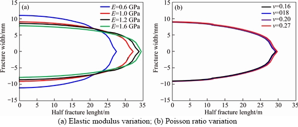
Figure 4 Fracture geometry under different rock properties:
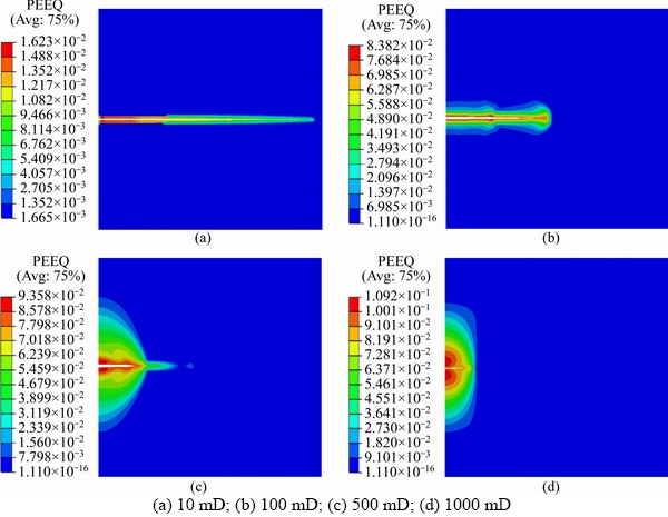
Figure 5 Fracture geometry under different reservoir permeability:
Some engineering factors have great influences on fracture propagation during the fracturing process. The fracturing fluid injection rate and fracturing fluid viscosity are main factors that can be directly and easily controlled during the process of the fracturing. The injection rate is changed to 1, 2, 3 and 4 m3/min, respectively. Other parameters are taken from Table 1. Figure 6 shows that it does not generate fractures in the reservoir when the injection rate is less than 1 m3/min; suitable fractures are produced when the injection rate is approximate to 3–4 m3 /min. In general, the higher the injection rate is, the larger the effective area of fracture induced by fracturing operation. High injection rate is advantaged to the fracture propagation.
The fracturing fluid viscosity is gradually changed to 10, 100, 500 and 1000 mPa·s, respectively. Other parameters are taken from Table 1. The fracturing fluid injection rate is 3 m3/min. The results are shown in Figure 7. The fracture is restricted to propagate when the fluid viscosity is less than 10 mPa·s. The vertical restriction to the fracture geometries is weakened with the increase of fracturing fluid viscosity. The study shows that the leak-off of fracture fluid is reduced under high fluid viscosity. The fracture fluid is mainly retained in the fractures. The increase of fracturing fluid viscosity is beneficial to fracture propagation.
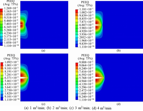
Figure 6 Fracture geometry under different fracturing fluid injection rate:

Figure 7 Fracture geometry under different fracturing fluid viscosity:
3 Field application
Frac-gravel packing completion technology has been conducted in some tests on 5 wells in weakly consolidated sandstone of SZ36-1 oilfield. The optimization of fracturing parameters is based on the rock properties and numerical model established. Fracturing design of weakly consolidated sandstone has large differences from conventional rocks. Fracturing design mainly includes three main points: firstly, the goal of fracturing design is to produce short and wide fractures to improve the flow conductivity of fracture that requires the fracture has characteristics of relatively small length and large width. Secondly, the preflush fluid and total fluid volume are small in addition to high sand content. Finally, selecting proppant should consider flow conductivity and particle size matching. The prediction model of fracture morphology is two-dimensional method, without considering the fracture height. Taking well-X of SZ36-1 for an example, the predicted results of fracture morphology are shown in Table 2.
Table 2 Optimization result of construction parameters for well-X
The construction parameters of frac-pack are shown in Table 3.
Frac-gravel packing operation was carried out in SZ36-1 oilfield of China. Figure 8 shows the production of well-X after frac-gravel packing operation. It obviously has the characteristics of high production after fracturing operation. Actual highest oil production is 58.54 m3/d that is more than 46% of production allocation. The late oil production is stable for a long time, the average production is 26.68 m3/d. Overall, frac-gravel packing technology has achieved good development effect.
Table 3 Optimization result of construction parameters for well-X
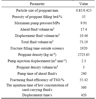
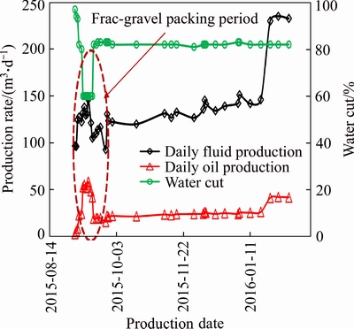
Figure 8 Production performance of SZ36-1well X after fracture
4 Conclusions
1) Numerical model of fracture initiation and propagation has been established considering the rock properties of weakly consolidated sandstone. The factors which influence fracture morphology can be divided into two major categories: geologic factors and engineering factors.
2) Fracture aperture is smaller in high elastic modulus. The low elastic modulus of rock is beneficial to induce short and wide fractures and control the fracture length. The Poisson ratio has almost no effect on the fracture geometry.
3) The large injection rate and high viscosity of fracturing fluid are advantageous to fracture initiation and propagation in weakly consolidated. The fracturing scale can be controlled by reasonable injection rate and fracturing fluid viscosity.
4) The leak-off of fracturing fluid to the formation is augmenting with the increase of formation permeability, and it is disadvantaged to fracture propagation. Frac-gravel packing technology is suitable for weakly consolidated sandstone, but reasonable construction parameters are important to fracturing design.
5) The numerical simulation of hydraulic fracturing will be put forward higher requirements because of the rock mechanics characteristics of weakly consolidated sandstone. It is worth exploring research direction to consider formation anisotropy, heterogeneity, and discrete fracture network.
References
[1] FENG Sheng-li, SHI Zhen-jun, WANG Yong-qiang. Application of high pressure pack sand control in Sebei gas field [J]. Special Oil & Gas Reservoirs, 2006, 13(3): 73–75. (in Chinese)
[2] QU Zhan-qing, SU Cheng, WEN Qing-zhi. Optimal design of parameters of sand control by frac-packing [J]. Special Oil & Gas Reservoirs, 2012, 19(6): 134–137. (in Chinese)
[3] GRUBERT D M. Evolution of a hybrid fracture/gravel-pack completion: Monopod platform, trading bay field, cook inlet, Alaska [J]. SPE Production Engineering, 1991, 6(4): 395–398.
[4] ROODHART L P, FOKKER P A, DAVIES D R, SHLYAPOBERSKY J, WONG G K. Frac and pack stimulation: Application design and field experience from the gulf of Mexico to Borneo [C]// SPE Annual Technical Conference and Exhibition. Society of Petroleum Engineers, 1993: 507–517.
[5] ZHANG Wei-dong, YANG Zhi-cheng, WEI Ya-meng. Advances in research of hydraulic fractures in unconsolidated sands [J]. Force and Application, 2014, 36(4): 396–402. (in Chinese)
[6] WANG T T, JIANG C W, GAO Z X, LI C X. Numerical simulation of sand load applied on high-speed train in sand environment [J]. Journal of Central South University, 2017, 24(2): 442–447.
[7] KHODAVERDIAN M, MCELFRESH P. Hydraulic fracturing stimulation in poorly consolidated sand: Mechanisms and consequences [C]// SPE Annual Technical Conference and Exhibition. Society of Petroleum Engineers, 2000: 1–13.
[8] CHANG H. Hydraulic fracturing in particulate materials [D]. Georgia Institute of Technology, 2004.
[9] DONG Y, DE PATER C J. Observation and modeling of the hydraulic fracture tip in sand [C]// The 42nd US Rock Mechanics Symposium (USRMS). California: American Rock Mechanics Association, 2008: Paper ARMA 08-377.
[10] GERMANOVICH L N, HURT R S, AYOUB J A. Experimental study of hydraulic fracturing in unconsolidated materials [J]. Tetrahedron Letters, 2012, 49(5): 888–892.
[11] GOLOVIN E, JASAREVIC H, CHUDNOVSKY A, DUDLEY J W, WONG G K. Observation and characterization of hydraulic fracture in cohesionless sand [C]// 44th US Rock Mechanics Symposium and 5th US- Canada Rock Mechanics Symposium. Utah, USA: American Rock Mechanics Association, 2010: 58–62.
[12] ZHOU Jia, DONG Yu-fei, de PETER C J, ZITHA P L J. Experimental study of the impact of shear dilation and fracture behavior during polymer injection for heavy oil recovery in unconsolidated reservoirs [C]// Canadian Unconventional Resources and International Petroleum Conference. Alberta, Canada: Society of Petroleum Engineers, 2010: 1–12.
[13] MANCHANDA R, OLSON J E, SHARMA M M. Permeability anisotropy and dilation due to shear failure in poorly consolidated sands [C]// SPE 152432, Hydraulic Fracturing Technology Conference. Woolands, 2012.
[14] HAIMSON B, FAIRHURST C. Initiation and extension of hydraulic fractures in rocks [J]. Society of Petroleum Engineers Journal, 1967, 7(3): 310–318.
[15] JIN Yan, ZHANG Xu-dong, CHEN Mian. Initiation pressure models for hydraulic fracturing of vertical wells in naturally fractured formation [J]. Acta Petrolei Sinica, 2005, 26(6): 113–114.
[16] REN Lan, ZHAO Jin-zhou, HU Yong-quan. Numerical calculation of rock breakdown pressure during hydraulic fracturing process [J]. Rock Mechanics and Engineering, 2009, 28 (s2): 3417–3422. (in Chinese)
[17] CARRIER B, GRANET S. Numerical modeling of hydraulic fracture problem in permeable medium using cohesive zone model [J]. Engineering Fracture Mechanics, 2012, 79: 312–328.
[18] LAI X D, AN F C, WANG Y H, ZHU H Y, JIN X C. Coupled flow, stress and damage modelling of interactions between hydraulic fractures and natural fractures in shale gas reservoirs [J]. International Journal of Oil, Gas and Coal Technology, 2016, 13(4): 359–390.
[19] ZHANG F, ZHU H, ZHOU H, GUO J, HUANG B. Discrete- element-method/computational-fluid-dynamics coupling simulation of proppant embedment and fracture conductivity after hydraulic fracturing [J]. Spe Journal, 2017, 22(2): 632–644.
[20] ZHANG G M, LIU H, ZHANG J, WU HA, WANG X X. Three-dimensional finite element simulation and parametric study for horizontal well hydraulic fracture [J]. Journal of Petroleum Science & Engineering, 2010, 72(3): 310–317.
[21] CHEN Z, BUNGER A P, ZHANG X. Cohesive zone finite element-based modeling of hydraulic fractures [J]. Acta Mechanica Solida Sinica, 2009, 22(5): 443–452.
[22] DO B C, LIU W, YANG Q D, SU X Y. Improved cohesive stress integration schemes for cohesive zone elements [J]. Engineering Fracture Mechanics, 2013, 107(7): 14–28.
[23] ZHU H Y, ZHAO X, GUO J C, JIN X, AN F. Coupled flow- stress-damage simulation of deviated-wellbore fracturing in hard-rock [J]. Journal of Natural Gas Science and Engineering, 2015, 26: 711–724.
[24] GUO J, ZHAO X, ZHU H, ZHANG X, PAN R. Numerical simulation of interaction of hydraulic fracture and natural fracture based on the cohesive zone finite element method [J]. Journal of Natural Gas Science & Engineering, 2015, 25: 180–188.
(Edited by FANG Jing-hua)
中文导读
疏松砂岩油藏水力压裂的数值模拟
摘要:压裂充填防砂技术有效改善了疏松砂岩油藏开发效果,具有实现增产与防砂的双重效果。由于疏松砂岩物性及力学的特殊性,其裂缝起裂与延伸机理较为复杂。为了研究水力裂缝延伸的机制,揭示压裂参数对疏松砂岩裂缝形态的影响,利用有限元软件建立了流固耦合有限元数值模型,重点分析了地层渗透率、压裂液黏度及排量对于裂缝延伸规律的影响。结果表明,低弹性模量有利于诱导形成短且宽裂缝并控制裂缝长度,而泊松比几乎不产生影响。高排量和高黏度压裂液裂缝有利于裂缝的起裂和延伸。当注入速率为3~4 m3/min和流体黏度超过100 mPa·s时将形成合适的裂缝。压裂液的滤失量随着地层渗透率的增加而上升。
关键词:疏松砂岩;压裂充填;水力压裂;裂缝扩展;数值模拟
Foundation item: Project(2016ZX05058-002-006) supported by National Science and Technology Major Projects of China; Project(2018CXTD346) supported by Innovative Research Team Program of Natural Science Foundation of Hainan Province, China
Received date: 2017-08-30; Accepted date: 2018-02-22
Corresponding author: DENG Jin-gen, PhD, Professor; Tel: +86-10-89733155; E-mail: dengjingen@126.com; ORCID: 0000-0003- 0984-9767

