An in situ measure method to study deposition mechanism of electroless Ni-P plating on AZ31 magnesium alloy
来源期刊:中国有色金属学报(英文版)2011年第12期
论文作者:秦铁男 马立群 姚妍 倪聪 赵相玉 丁毅
文章页码:2790 - 2797
关键词:镁合金;化学镀Ni-P;形核;沉积速度
Key words:magnesium alloy; electroless Ni-P deposition; nucleation; coating rate
摘 要:设计一种原位方法去测量AZ31镁合金在化学镀Ni-P过程中基体在镀液中的开路电位和体积表面的镀层形貌变化。通过开路电位曲线、扫描电子显微镜和能谱分析研究AZ31镁合金化学镀Ni-P的沉积机理。结果表明:化学镀Ni-P的沉积过程包括镀层的形成过程和镀层的增厚过程,其中镀层的形成过程又包括镍晶核的形核和长大过程、镀层的二维扩展过程和镀层的三维搭接过程。扫描电镜分析证实了Ni-P镀层的球形瘤状物不仅形成于镀层的增厚阶段,同样也形成于Ni-P镀层的初始沉积阶段。不同沉积阶段的沉积速度变化分别与各自的沉积机理对应。
Abstract:
An in situ method was designed to measure a continuous open circuit potential (OCP) curve of AZ31 magnesium alloy and to observe the morphology variation of Ni-P coating during the process of the electroless plating. The deposition mechanism of the electroless Ni-P plating on AZ31 Mg alloy was studied by OCP curve, scanning electron microscopy (SEM), and energy dispersion spectroscopy (EDS). The process of electroless Ni-P plating contains the coating formation stage and the coating growth stage. The formation stage includes three procedures, i.e., the nucleation and growth of Ni crystallites, the extension of the coating in two-dimensional (2D) direction and the coalescence of the coating along three-dimensional (3D) direction. SEM investigations demonstrate that the spherical nodules of the Ni-P coating are not only formed during the coating growth stage, but also generated in the initial deposition stage of electroless Ni-P plating. The variation of the coating rates at different deposition stages corresponds to the deposition mechanism of their respective deposition stage.

QIN Tie-nan, MA Li-qun, YAO Yan, NI Cong, ZHAO Xiang-yu, DING Yi
College of Materials Science and Engineering, Nanjing University of Technology, Nanjing 210009, China
Received 8 December 2010; accepted 8 June 2011
Abstract: An in situ method was designed to measure a continuous open circuit potential (OCP) curve of AZ31 magnesium alloy and to observe the morphology variation of Ni-P coating during the process of the electroless plating. The deposition mechanism of the electroless Ni-P plating on AZ31 Mg alloy was studied by OCP curve, scanning electron microscopy (SEM), and energy dispersion spectroscopy (EDS). The process of electroless Ni-P plating contains the coating formation stage and the coating growth stage. The formation stage includes three procedures, i.e., the nucleation and growth of Ni crystallites, the extension of the coating in two-dimensional (2D) direction and the coalescence of the coating along three-dimensional (3D) direction. SEM investigations demonstrate that the spherical nodules of the Ni-P coating are not only formed during the coating growth stage, but also generated in the initial deposition stage of electroless Ni-P plating. The variation of the coating rates at different deposition stages corresponds to the deposition mechanism of their respective deposition stage.
Key words: magnesium alloy; electroless Ni-P deposition; nucleation; coating rate
1 Introduction
Compared with the conventional metals,Mg alloys have drawn wide interests because of their better properties, such as high specific tenacity and specific stiffness, high damping characteristics, and well electromagnetic shielding properties. In particular, their high specific strength makes them attractive for mass reduction in portable microelectronics, aeronautical and aerospace, telecommunications and automobile industries, etc [1-3]. However, the poor corrosion resistance is still a consistent issue that limits the extensive use of Mg alloys [4]. Because of the low standard electrode potential (-2.37 V vs SHE) [5], Mg will easily form a galvanic corrosion system with another metal and/or a microgalvanic corrosion system with impurities and secondary phases (such as Mg17Al12, AlMn and Al8Mn5) in an aqueous environment [5-8]. Consequently, the corrosion resistance of Mg and its alloys is unsatisfied in practical environment.
In general, there are two methods for improving the corrosion resistance of Mg alloys, namely metallurgy and surface treatment [9]. Metallurgical manipulation can provide an effective way to enhance the corrosion resistance of Mg by adding some beneficial elements, such as Al, Zn and Mn, and/or reducing the impurity elements content [8, 10-11]. Another effective way to suppress the corrosion of Mg alloys is the surface coating technique [3, 12]. If the coating is uniform, non-porous and chemically stable, the coating on the surface of Mg alloys can form a barrier between the matrix metal and the corrosion medium, thereby suppressing the corrosion of Mg alloys. Among the various surface treatment techniques, electroless Ni-P plating is considered one of the most effective coating methods due to its perfect comprehensive properties, such as good corrosion and wear resistance, deposit uniformity, magnetic and solderability [13-14]. However, Mg and its alloys are known as “difficult to plate” metals because of their poor corrosion resistance, thus electroless Ni-P deposition on Mg alloys needs special bath formulations and pretreatment methods to restrain the corrosion of Mg matrix metal in the plating bath [15]. According to the previous literatures [1-2, 14-15], the fluoride film formed on Mg alloys during hydrofluoric acid activating treatment process is capable to not only prevent the Mg substrates from being oxidized, but also inhibit the corrosion of the Mg substrates in the plating bath during the initial deposition stage of electroless Ni-P plating. LI et al [16] have studied the passive mechanism of AZ91 Mg alloy in the fluoride solution and indicated that an insoluble Mg fluoride (MgF2) film was generated on the surface of the Mg alloy during the hydrofluoric acid activating process. Moreover, the deposition mechanism of electroless Ni-P plating on the different fluorinated Mg alloys was also investigated in Refs. [1, 17-18].
However, the literature regarding the study on the morphology variation of the coating in the initial deposition stage presented an obvious randomness for the timing for observing the morphology of the coating. This randomness is caused by the different coating rates which different Mg substrates, pretreatment technologies and bath formulations would contribute to. In addition, there is no standard observation time for the morphology variation, which may affect the analysis for the deposition mechanism in the initial deposition stage. In this work, in order to make the timing of observing the coating morphology more reasonable, an in situ measure method was designed to obtain a continuous OCP―time curve and the morphology variation of the coating during the electroless plating process. The relationship among the OCP, the plating time and the surface morphology of the samples was investigated to illustrate the deposition mechanism of electroless Ni-P plating on the fluorinated AZ31 Mg alloy.
2 Experimental
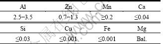
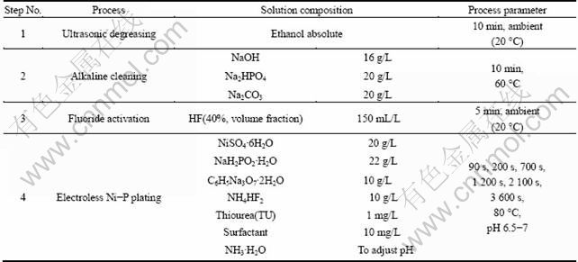
Commercially extruded AZ31 Mg alloy, with dimensions of 5 cm×2 cm×0.1 cm, was selected as the substrate material. The nominal chemical composition of the alloy is listed in Table 1. The detailed procedures of electroless Ni-P plating in this experiment are given in Table 2. The pretreatment technology was comprised of ultrasonic degreasing, alkaline cleaning and fluoride activation. In some literatures [1-2, 12-13], the acid pickling was used to roughen the surface of the Mg alloys for improving the adhesion strength between the coating and the substrate; but in this experiment, the acid pickling was not implemented in the pretreatment process to avoid the detrimental effect of a rough surface on the nucleation observation and the coating growth on the fluorinated AZ31 Mg alloy.
Table 1 Chemical compositions of AZ31 Mg alloy (mass fraction, %)
The AZ31 Mg alloy electrodes were prepared by the following methods. Because the thickness of the AZ31 samples is only 0.1 cm, the common mechanical contact by a screw followed by a sealing is not applicable. The AZ31 substrates were electroless plated to insure that the AZ31 alloy and the copper wires can be welded together. The as-deposited samples were cut into small pieces of 1 cm×1 cm×0.1 cm. Then, the small samples were welded with plastic isolated copper wires separately. Subsequently, they were sealed with epoxy resin and made the working area to be 1 cm2. After the epoxy resin solidified, the as-prepared electrodes were mechanically polished to expose the Mg alloy substrate with emery paper (600# and 1000#) and polishing cloth, and then washed with water and degreased with ethanol.
Table 2 Process steps of electroless Ni-P plating on AZ31 Mg alloy
The OCP―time curves of AZ31 alloy electrodes were measured during the plating process on a CHI 660B electrochemical workstation. A three-electrode cell was set up with six AZ31 working electrodes, a graphite counter electrode and an Ag/AgCl reference electrode, as shown in Fig. 1. The evident difference between the present work and the usual case is that several multipled AZ31 alloy electrodes were used as the working electrodes simultaneously when measuring the OCP―time curve during the plating. The distance between each working electrode and the reference electrode was equivalent. The electrodes were taken out of the bath at different time intervals of 90, 200, 700, 1 200, 2 100 and 3 600 s and washed with absolute ethanol. The surface morphologies and the composition of the coating were characterized by a JSM-5610LV scanning electron microscope (SEM) with energy dispersive spectroscope (EDS).
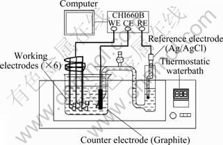
Fig. 1 Schematic diagram of three-electrode system
3 Results and discussion
Figure 2 shows the OCP of the AZ31 electrodes as a function of plating time. The curve demonstrates that the OCP of the AZ31 electrodes in the bath increased rapidly and reached a relatively steady value after 300 s (stage A), flattened for a while (stage B), then decreased quickly (stage C). Eventually, the OCP became relatively stable even though there was a slight increase after 2 000 s.
In stage A, the OCP increased rapidly as a consequence of the rapid formation of spherical nodules on the exposed Mg substrate, as presented in Fig. 3(a) and Fig. 3(b), excepting for the adsorption of ions and the charging of double electron layers. When the exposed Mg substrate was coated entirely, the OCP reached a steady value. Yet the formation mechanism of the spherical nodules in the initial deposition stage had not been reported. A possible explanation of this phenomenon was proposed. Because the defect of the flouride film was formed by the potential difference between α phase and Mn-Al phase [19-22], the exposed Mg substrate was preferentially dissolved into Mg2+ when the electrodes were immersed into the bath. Based on the corrosion mechanism of Mg alloys proposed by SONG and ATRENS [4], the active hydrogen atoms were produced during the corrosion process of the exposed AZ31 substrate, as shown in Eq. 1 and Eq. 2. Next, Ni2+ ions in the bath were reduced to Ni grains by these hydrogen atoms. But the effect of Mg corrosion was just limited to the beginning time before the Mg substrate was coated. As exhibited through Eqs. 3-5, the autocatalytic reactions of electroless Ni-P plating began to proceed with Ni as the catalyst of the oxidation reaction of hypophosphite. All the reaction equations of the reaction process are as follows:
![]() (1)
(1)
![]() (2)
(2)
![]() (3)
(3)
![]() (4)
(4)
![]() (5)
(5)
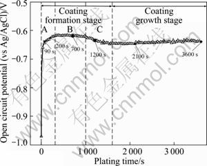
Fig. 2 OCP―time curve recorded for AZ31 electrodes during plating
During the reaction process, the Ni grains grew up into the spherical nodules, as shown in Figs. 3(a), 3(b) and Fig. 4. In addition, the chemical composition of the spherical nodules is shown in Fig. 4. Less P content was found in the early deposition stage, which is consistent with Refs. [17] and [18], indicating that the spherical nodules are the product of the autocatalytic reaction with sodium hypophosphite participating as stated in Eq. 5. The peaks of Al and Mg are due to the characteristics of the EDS analysis, which contains the analysis area and depth. This means that the Al and Mg peaks are mainly caused by the influence of substrate.
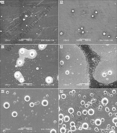
Fig. 3 SEM images of AZ31 electrodes plated for different time: (a) 90 s; (b) 200 s; (c) 700 s; (d) 1 200 s; (e) 2 100 s; (f) 3 600 s
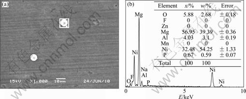
Fig. 4 Morphology (a) and composition (b) of spherical nodules on surface of AZ31 electrode plated for 200 s
In the next stage (stage B), the nodules acted as the deposition active site for the deposition reaction and the coating extended into 2D direction, centering on the spherical nodules, as shown in Fig. 3(c). Because the fluoride (MgF2) film can inhibit the process of the nucleation and the extension of the coating [17, 23], the reaction rate in this stage was so slow and the OCP reached a steady state. Figure 5(c) demonstrates that some rectangular block Ni crystallites nucleated beneath the fluoride film around the spherical nodules during the same period as the spherical nodules grew, owing to the replacement reaction as exhibited in Eq. 6, which is the same as the result reported by Refs. [1] and [17].
![]() (6)
(6)
The Ni crystallites were beneficial to the extension of the coating into 2D direction and made the coalescence of the coating along 3D direction easier. Eventually, they were embedded in the Ni-P coating after the coalescence of the coating, as presented in Fig. 5(b). Consequently, in view of the variation of the OCP and the surface morphology of the coating in the initial stage of electroless deposition, it can be deduced that the generation of rectangular block Ni crystallites around the spherical nodules is the rate controlling step in the coating formation stage. Moreover, it was predicted from Fig. 3(c) that the different states of the spherical nodules and the rectangular block Ni crystallites existed simultaneously in the initial deposition stage, which may be attributed to the different formation mechanisms of the spherical nodules and the rectangular block Ni crystallites, including the autocatalytic reaction and the Ni replacement reaction.
With a drastic decrease of the potential after 1 000 s (stage C), the coalescence of the coating along 3D direction became the major process of electroless Ni-P plating, as presented in Fig. 3(d). There are two possible reasons for this process. One is that an increasing number of rectangular block Ni crystallites nucleated through the MgF2 film accelerated the extension of the coating along 2D direction. The other is that the as-formed coating which had the catalytic activity for the autocatalytic reaction promoted the further growth of the coating. It can be found in Fig. 6 that there are two layers at the edge of the coating and the grains of Ni-P deposits in the upper layer are bigger than those in the lower layer, which indicates that the coating is thickened by layers.
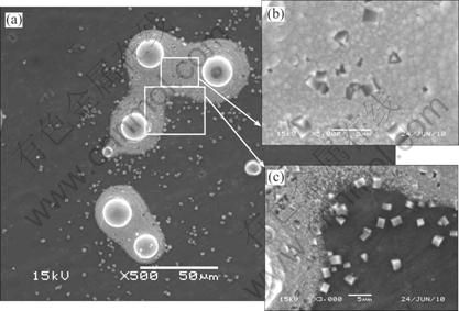
Fig. 5 SEM images at different magnifications of AZ31 electrode plated for 700 s
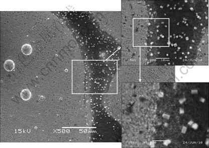
Fig. 6 SEM images at different magnifications of AZ31 electrode plated for 1 200s
In the coating growth stage, the Mg substrate was coated thoroughly and the spherical nodules continued to grow up, as presented in Fig. 3(e). Because the deposits had the catalytic activity for the reaction of electroless Ni-P plating, the coating thickened up quickly. When the plating time reached 3 600 s, more and more spherical nodules appeared in the coating. In previous reports [24], it is commonly recognized that the formation of the spherical nodular feature is related to the internal stress accumulation and the lower surface energy of the hemispherical deposit during the depositing process, but the spherical nodules were also found in the initial stage of electroless plating in the present work, as presented in Fig. 3(b) and Fig. 3(c). Thus, a further viewpoint about the formation mechanism of the spherical nodules was proposed that the spherical nodules not only formed in the coating growth stage because of the internal stress and the surface energy, as shown in Fig. 3(f), but also evolved from the autocatalytic reaction expressed through Eqs. (3)-(5) in the initial deposition stage.
By analyzing Fig. 2 and Fig. 3, the relationship among the OCP, the plating time and the morphology alteration of the coating during the process of electroless Ni-P plating has been built. It can be seen that the whole deposition process can be divided into two stages, coating formation stage and coating growth stage. Moreover, the coating formation stage contains three simultaneous coating-forming processes, i.e., the nucleation and growth of Ni crystallites, the extension of the coating into 2D direction and the coalescence of the coating along 3D direction. Also the feasibility of the in situ measuring method mentioned above has been further proved. The method can also be applied to investigating electroless depositing other metals on different metal materials. It was necessary to point out that the OCP―time curves in other studies may be different as a result of the difference in substrate materials, bath compositions or pretreatment technologies. However, the relationship between the variation of OCP and the alteration of the coating morphology will still be found in this method because the OCP of the samples during the electroless plating process is bound to transform with the enlarged coverage area of substrate surface.
Figure 7 shows the deposition mass gain as a function of the plating time, and the coating rate in different deposition stages can be evaluated. The 2D extension and the 3D coalescence of the coating were proceeded rapidly at the same time in stage C, which resulted in a higher coating rate. The result derived from the coating rate curve in our work is similar to the result demonstrated in Ref. [1]. The different coating rates at different deposition stages corresponded to the deposition mechanism of the foregoing deposition stage. The average coating rate of the whole plating process (1 h) is around 22 μm/h if the density of the Ni-P deposits is appointed as 8 g/cm3.
Figure 8 shows the chemical composition on the surface of the specimens plated for different time. The variations of the matrix elements and the generated elements on the surface of the samples are presented in Fig. 8(a) and Fig. 8(b), respectively. The Ni and P contents increased while the content of the matrix elements decreased and the variation trend became more distinct beyond 200 s. The obvious increase in Ni and P contents after 700 s was in accordance with the rapid increase of the coating rate in the stage C. The disappearance of the matrix elements also reflected the compactness of the coating indirectly. The decline of P content from 5.5% at 2 100 s to 5.0% at 3 600 s is attributed to the periodic variation of P content in the deposits, which has been confirmed in Ref. [2].
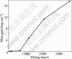
Fig. 7 Deposition mass gains as function of plating time
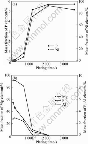
Fig. 8 Surface chemical composition variation of AZ31 electrodes plated with time
4 Conclusions
1) A novel in situ measuring method was designed to investigate the relationship of open circuit potential, plating time and surface morphology of AZ31 Mg alloy during the electroless Ni-P plating process. The result confirms that the OCP of the samples is bound to transform with the enlarged coverage area of substrate surface in the plating process, and the method is equally applied to studying electroless depositing other metals on different metal materials.
2) From the analysis of the OCP and the surface morphology variation of the samples, it can be seen that the deposition process can be divided into two stages, coating formation stage and coating growth stage. The coating formation stage contains three simultaneous coating-forming processes, i.e., the nucleation and growth of Ni crystallites, the extension of coating into 2D direction and the coalescence of coating along 3D direction.
3) The spherical nodules of Ni-P coating are not only formed in the coating growth stage, but also generated in the initial stage of electroless Ni-P plating. The variation of the coating rates at different deposition stages corresponds to the deposition mechanism of their respective deposition stage.
References
[1] LIU Z M, GAO W. The effect of substrate on the electroless nickel plating of Mg and Mg alloys [J]. Surface & Coating Technology, 2006, 200(11): 3553-3560.
[2] AMBAT R, ZHOU W. Electroless nickel-plating on AZ91D magnesium alloy: Effect of substrate microstructure and plating parameters [J]. Surface & Coating Technology, 2004, 179(2-3): 124-134.
[3] GRAY J E, LUAN B. Protective coating on magnesium and its alloys―A critical review [J]. Journal of Alloys and Compounds, 2002, 336(1-2): 88-113.
[4] SONG G L, ATRENS A. Corrosion mechanisms of magnesium alloys [J]. Advance Engineering Materials, 1999, 1(1): 11-33.
[5] LIU L J, SCHLESINGER M. Corrosion of magnesium and its alloys [J]. Corrosion Science, 2009, 51(8): 1733-1737.
[6] SONG G L, JOHANNESSON B, HAPUGODA S, S T. JOHN D. Galvanic corrosion of magnesium alloy AZ91D in contact with an aluminium alloy, steel and zinc [J]. Corrosion Science, 2004, 46(4): 955-977.
[7] SONG G L, ATRENS A. Understanding magnesium corrosion―A framework for improved alloy performance [J]. Advance Engineering Materials, 2003, 5(12): 837-858.
[8] ZENG R C, ZHANG J, HUANG W J, DIETZEL W, KAINER K U, BLAWERT C, KE W. Review of studies on corrosion of magnesium alloys [J]. Transaction of Nonferrous Metals Society of China, 2006, 16(s2): s763-s771.
[9] GU Chang-dong, LIAN Jian-she, LI Guang-yu. Electroless Ni-P plating on AZ91D magnesium alloy from a sulfate solution [J]. Journal of Alloys and Compounds, 2005, 391(1-2): 104-109.
[10] SONG G L, ATRENS A. Recent insights into the mechanism of magnesium corrosion and research suggestions [J]. Advance Engineering Materials, 2007, 9(3): 177-183.
[11] BALLERINI G, BARDI U, BIGNUCOLO R, CERAOLO G. About some corrosion mechanisms of AZ91D magnesium alloy [J]. Corrosion Science, 2005, 47(9): 2173-2184.
[12] LI J Z, SHAO Z C, ZHANG X, TIAN Y W. The electroless nickel-plating on magnesium alloy using NiSO4・6H2O as the main salt [J]. Surface & Coating Technology, 2006, 200(9): 3010-3015.
[13] MAHALLAWY N E, BAKKAR A, SHOEIB M, PALKOWSKI H, NEUBERT V. Electroless Ni-P coating of different magnesium alloys [J]. Surface & Coating Technology, 2008, 202(21): 5151-5157.
[14] LI J Z, TIAN Y W, HUANG Z Q, ZHANG X. Studies of the porosity in electroless nickel deposits on magnesium alloy [J]. Applied Surface Science, 2006, 252(8): 2839-2846.
[15] SONG Y W, SHAN D Y, HAN E H. A study on the pretreatment of direct electroless nickel plating on magnesium alloys AZ91D [J]. Materials Science Forum, 2005, 488-489: 835-838.
[16] LI Jian-zhong, HUANG Jiu-gui, TIAN Yan-wen, LIU Chang-sheng. Corrosion action and passivation mechanism of magnesium alloy in fluoride solution [J]. Transactions of Nonferrous Metals Society of China, 2009, 19(1): 50-54.
[17] XIANG Y H, HU W B, LIU X K. A study on surface state during the pretreatment of electroless nickel plating on magnesium alloys [J]. Trans IMF, 2001, 79(1): 27-29.
[18] XIANG Y H, HU W B, LIU X K. Initial deposition mechanism of electroless nickel plating on magnesium alloys [J].Trans IMF, 2001, 79(1): 30-32.
[19] PARDO A, MERINO M C, COY A E, ARRABAL R, VIEJO F, MATYKINA E. Corrosion behaviour of magnesium/aluminium alloys in 3.5 wt.% NaCl [J]. Corrsion Science 2008, 50(3): 823-834.
[20] FELIU S JR, PARDO A, MERINO M C, COY A E, VIEJO F, ARRABAL R. Correlation between the surface chemistry and the atmospheric corrosion of AZ31, AZ80 and AZ91D magnesium alloys [J]. Applied Surface Science, 2009, 255(7): 4102-4108.
[21] MERINO M C, PARDO A, ARRABAL R, MERINO S, CASAJUS P, MOHEDANO M. Influence of chloride ion concentration and temperature on the corrosion of Mg-Al alloys in salt fog [J]. Corrosion Science, 2010, 52(5): 1696-1704.
[22] HAO Xian-chao, ZHOU Wan-qiu, ZHENG Zhi-guo. Study on electrochemical corrosion behaviors of AZ31 magnesium alloys in NaCl solution [J]. Journal of Shenyang Normal University: Natural Science, 2004, 22(2): 117-121. (in Chinese)
[23] GUO Dong, FAN Zhan-guo, YANG Zhong-dong, ZHAO Lin, GAO Peng. Effects and characteristics of MgF2 during electroless nickel plating of magnesium alloys [J]. The Chinese Journal of Nonferrous Metals, 2007, 17(5): 789-794. (in Chinese)
[24] ZHOU Xiao-wei, JIN Hui-ming, ZHANG Lin-nan. Influence of pH value on microstructure and thermal stability of Ni-P electroless coating prepared in acidic condition [J]. Chinese Chemical Letters, 2009, 20(7): 845-848.
秦铁男, 马立群, 姚 妍, 倪 聪, 赵相玉, 丁 毅
南京工业大学 材料科学与工程学院,南京 210009
摘 要:设计一种原位方法去测量AZ31镁合金在化学镀Ni-P过程中基体在镀液中的开路电位和体积表面的镀层形貌变化。通过开路电位曲线、扫描电子显微镜和能谱分析研究AZ31镁合金化学镀Ni-P的沉积机理。结果表明:化学镀Ni-P的沉积过程包括镀层的形成过程和镀层的增厚过程,其中镀层的形成过程又包括镍晶核的形核和长大过程、镀层的二维扩展过程和镀层的三维搭接过程。扫描电镜分析证实了Ni-P镀层的球形瘤状物不仅形成于镀层的增厚阶段,同样也形成于Ni-P镀层的初始沉积阶段。不同沉积阶段的沉积速度变化分别与各自的沉积机理对应。
关键词:镁合金;化学镀Ni-P;形核;沉积速度
(Edited by LI Xiang-qun)
Foundation item: Project supported by the Priority Academic Program Development of Jiangsu Higher Education Institutions (PAPD), China
Corresponding author: MA Li-qun; Tel: +86-25-83587243; Fax: +86-25-83240205; E-mail: maliqun@njut.edu.cn
DOI: 10.1016/S1003-6326(11)61125-4

