
Structure defect prediction of single crystal turbine blade by dendrite envelope tracking model
WANG Tong-min(王同敏)1, Itsuo OHNAKA2, Hideyuki YASUDA2, SU Yan-qing(苏彦庆)3, GUO Jing-jie(郭景杰)3
1. School of Materials Science and Engineering; State Key Laboratory. of Materials Modification by Laser,
Ion and Electron Beams, Dalian University of Technology, Dalian 116024, China;
2. Graduate School of Engineering, Osaka University, Osaka 565-0871, Japan;
3. School of Materials Science and Engineering, Harbin Institute of Technology, Harbin 150001, China
Received 10 April 2006; accepted 25 April 2006
Abstract: The structure defects such as stray grains during unidirectional solidification can severely reduce the performance of single crystal turbine blades. A dendrite envelope tracking model is developed for predicting the structure defects of unidirectional solidification turbine blade. The normal vector of dendrite envelope is estimated by the gradient of dendrite volume fraction, and the growth velocity of the dendrite envelope (dendrite tips) is calculated with considering the anisotropy of grain growth. The solute redistribution at dendrite envelope is calculated by introducing an effective solute partition coefficient. Simulation tests show that the solute-build-up due to the rejection at envelope greatly affects grain competition and consequently solidification structure. The model is applied to predict the structure defects (e.g. stray grain) of single crystal turbine blade during unidirectional solidification. The results show that the developed model is reliable and has the following abilities: reproduce the growth competition among the different-preferential-direction grains; predict the stray grain formation; simulate the structure evolution (single crystal or dendrite grains).
Key words: turbine blade; single crystal; stray grain; dendrite envelope tracking; modeling
1 Introduction
Several modeling approaches have been carried out for the structure defects prediction and process optimization during unidirectional solidification. They can be classified into two categories: one is analytical approaches, which predict grain defects based on the process parameters, mainly the thermal gradient, G, and the velocity of the isotherms, v. The curves or windows in G―v diagrams show the limits between reliable and inappropriate casting conditions[1]; the other one is numerical approach, which predict structures based on grain nucleation-growth simulation, for example, Gandin and Rappaz et al[2-5] have done much work to predict the unidirectional solidification structure by using cellular automaton-finite element(CAFE) method and have obtained reasonable results. LI et al[6] applied CA model to simulate the equiaxed grains of turbine blades. WANG et al[7, 8] developed a Cellular Automaton-Monte Carlo(CAMC) coupling model to simulate the dendritic grain growth. The CAMC model has both advantages of probabilistic and deterministic models. XU et al[9] developed the dendritic grain growth model based on the dendrite shape function. The models above were applied in the scale of grain and have no comprehensive consideration of the effect of solutal field on the grain growth. Several other models are used for simulating the dendrite morphology. Nastac[10] developed a liquid/solid interface tracking model to simulate the evolution of unidirectional solidification structure. ZHU et al[11] developed a Modified Cellular Automaton model for simulating the dendritic growth. LI et al[12, 13] simulate the dendrites of directional solidification by using phase field model.
Solute can transfer from the mushy zone by diffusion or convection in unidirectional solidification with rather low growth rate. Therefore, it is valuable to discuss the effect of solute reject from the mushy zone on the solidification structure. This paper firstly presents a tracking model of the dendrite envelope and the solute redistribution calculation at the dendrite envelope. Then the model is applied to predict the defects of single crystal turbine blade during unidirectional solidification.
2 Model description
As shown in Fig.1, the calculation domain is enmeshed with micro cells of which geometry is square (2D) or cubic (3D). The cells are classified as three groups in terms of dendrite envelope position. One is “liquid cell” that contain only the liquid phase. Another is “envelope cell” that contain the dendrite envelope interface. The other is “solidifying cell” in which the dendrite envelope interface has already passed. Therefore, the “solidifying cell” is partially or completely solidified. The envelope interfaces in each “envelope cell” are tracked at each time step by calculating the interface parameters: the normal vector n, the normal velocity vn, and the interface area S. The angle α, between the preferential growth direction p, and the interface normal direction n, is introduced in the present method for considering the growth anisotropy of dendrite. The state of cell is changed from “liquid” to “envelope” and “solidifying” with the proceeding of grain nucleation and growth.
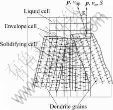
Fig.1 Schematic diagram of dendrite envelope tracking method
3 Solute calculation and nucleation simulation
The governing discrete equation for the solute diffusion in liquid is derived with the direct finite difference method(DFDM)[14] and expressed as follows:
 (1)
(1)
where V is cell volume, c is solute concentration, DL is solute diffusion coefficient in the liquid phase, S is surface area, Δt is time step, α is cell size, the subscripts i, j denote the current cell and its neighbor cell, respectively.
The solute redistribution at the dendrite envelope is done by introducing an effective solute partition coefficient, ke. It is defined as
 (2)
(2)
where  and
and  are the average concentration inside and outside the dendrite envelope, respectively. It should be pointed out that the effective solute partition coefficient is neither the equilibrium partition coefficient nor the effective partition coefficient at the solid/liquid interface.
When the dendrite volume fraction (volume occupying ratio) in an “envelope cell” is increased by Δfe due to the grain nucleation and growth, the amount of solute rejected from the “envelope cell”, ΔGr, is given by
 (3)
(3)
This rejected solute is distributed to the neighboring liquid cells of the “envelope cell” uniformly.
Constitutional undercooling is used for the grain growth and nucleation, which is calculated by
ΔT=TL+m(cL-c0) -T (4)
where c0 is initial concentration of the alloy, TL is the liquidus temperature at the initial concentration, m is the liquidus slope, and cL is the liquid concentration.
Heterogeneous nucleation is calculated by using the instantaneous model proposed by Rappaz et al[15]. The nuclei density at a given undercooling is calculated with the integral of Gaussian distribution. Two sets of Gaussian distribution parameters are separately used for the mold wall and melt bulk to characterize their different nucleation ability. Once a cell nucleates, a random integer that represents the crystallographic orientation is given to the cell. The state of the nucleated cell is changed from “liquid” to “envelope”.
4 Dendrite envelope tracking algorithm
As shown in Fig.1, the normal vector n(nx, ny, nz) is calculated with the dendrite volume fraction gradient[16]:
 (5)
(5)
As shown in Fig.2, the six preferential <100> growth directions of each orientation are described with the three vectors: p1, p2, p3 which are generated with three Euler angles,  . We calculate angles between the normal direction and preferential directions by using Eqn.(6).
 (6)
(6)
Then the minimum angle among α1, α2 and α3 is selected, namely
α=min(α1, α2, α3) (7)
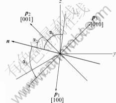
Fig.2 Angles between preferential and normal directions
The growth rate of the dendrite envelope in the preferential orientation, vtip(ΔT), is calculated with the fitted polynomial approximation based on the KURZ, GIOVANOLA and TRIVEDI(KGT) growth kinetics model[17, 18].
The increment of dendrite volume fraction is calculated by
 (8)
(8)
where f(α) is the anisotropy factor to characterize the preferential growth of dendrite, which is a function of α, in present study, f(α)=cos α. The different characters can be obtained by adjusting the expression of f(α)[16].
When an “envelope cell” is occupied by the dendrite envelope completely, the dendrite volume fraction of 10-4 is distributed to its neighboring liquid cells as propagation “seeds”, and the orientation of the “envelope cell” is also assigned to these cells. The “envelope cell” is changed to “solidifying cell”, and each neighbor liquid cell is changed to “envelope cell”.
5 Results and discussion
Fig.3 shows the simulated structure and concentration of a simple casting (super alloy IN738LC). In case of ke=0.99, isosolutal lines and dendrite grains tend to be parallel each other. However, they become wavy due to the high solute rejection at the envelope in case of ke= 0.95. In this case, the competition among the growing dendrite grains is significant. Some grains with favorite orientation grow fast while reject the solute aside to hinder the growth of their neighbors leading to a wavy shape of dendrite envelope. The simulated results indicate that the solute rejection from the mushy zone greatly affects the dendrite envelope that can not be negligible in case of small ke. The coefficient, ke, depends on not only physical properties but also solidification conditions such as convection, cooling rate and temperature gradient. Finding ways to determine its value quantitatively is expected.
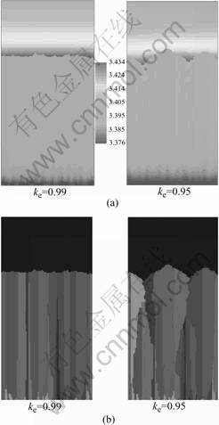
Fig.3 Simulated results with variant ke: (a) Concentration; (b) Structure
Fig.4 shows the comparison of grain structure between experiment and simulation. In case of the withdrawal rate 50 mm/h (see Fig.4(a)), single crystal turbine blades are obtained for both simulation and experiment. No stray grains are observed. However, in case of 600 mm/h (see Fig.4(b)), several stray grains appear in the turbine part and a number of dendrite grains grow from the starter through the whole turbine blade in the simulated result. The experimental result validates the findings of simulation to some extent. However the quantitative comparison is hard to achieve because of the poor quality of experiment photo.
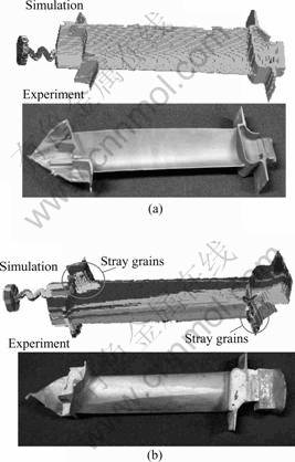
Fig.4 Unidirectional solidified structure of turbine blade in case of different withdrawal rates: (a) 50 mm/h; (b) 600 mm/h
6 Conclusions
1) A dendrite envelope tracking model has been developed in this study. The solute rejection at the dendrite envelope was considered by introducing an effective solute partition coefficient, ke. The simulation results show that the grain growth is significantly affected by the solute rejection in case of small ke.
2) The developed model was applied to predict the structure defect of single crystal turbine blade. It is shown that the model is capable of predicting grain structure evolution and stray grain formation. The corresponding experiments validated the simulations showing compatible agreement.
References
[1] BUSSAC A, GANDIN C A. Prediction of a process window for the investment casting of dendirtic single crystals [J]. Mater Sci Eng, 1997, A237: 35-42.
[2] GANDIN C A, DESBIOLLES J L, RAPPAZ M, TH?VOZ P H. Three-dimensional cellular automaton-finite element model for the prediction of solidification grain strucutres [J]. Metall Mater Trans, 1999, 30A: 3153-3165.
[3] GANDIN C A, RAPPAZ M, DESBIOLLES J L. 3D modelling of dendritic grain structures in a turbine blade investment cast part [A]. BEECH J, JONES H. Proceedings of the 4th Decennial International Conference on Solidification Processing [C]. Sheffield, BBR Solutions Ltd, 1997: 289-294.
[4] KERMANPUR A, VARAHRAM N, DAVAMI P, RAPPAZ M. Thermal and grain-structure simulation in a land-based turbine blade directionally solidified with the liquid metal cooling process [J]. Metall Mater Trans, 2000, 31B: 1293-1305.
[5] GANDIN C A. From constrained to unconstrained growth during directional solidification [J]. Acta Metall, 2000, 48: 2483-2501.
[6] LI Q A, LI D Z, QUAN B N. Modeling of dendritic growth by means of cellular automaton method [J]. Acta Physica Sinica, 2004, 53(10): 3477-3481.(in Chinese)
[7] WANG T M, JIN J Z, ZHENG X S. A CA/MC model for the simulation of grain structures in solidification processes [J]. J Mater Sci, 2002, 37: 2645-2650.
[8] WANG T M, JIN J Z, OHNAKA I. A novel simulation method for the prediction of dendritic grain structures in solidification [J]. Int J Cast Metals Res, 2002, 15: 399-404.
[9] XU Q Y, FENG W M, LIU B C. Stochastic modeling of dendritic microstructure of aluminum alloy [J]. Int J Cast Metals Res, 2002, 15: 225-230.
[10] NASTAC L. Numerical modeling of solidification morphologies and segregation patterns in cast dendritic alloys [J]. Acta Mater, 1999, 47(17): 4253-4262.
[11] ZHU M F, CHEN J, SUN G X, HONG J P. Numerical modeling of dendritic growth [J]. Acta Metallurgica Sinica, 2005, 41(6): 583-587.(in Chinese)
[12] LI X Z, GUO J J, SU Y Q, WU S P, FU H Z. Formation mechanism of band structure and phase selection during directional solidification of peritectic alloys, i. formation mechanism of band structure [J]. Acta Metallurgica Sinica, 2005, 41(6): 593-598. (in Chinese)
[13] GUO J J, LI X Z, SU Y Q, WU S P, FU H Z. Formation mechanism of band structure and phase selection during directional solidification of peritectic alloys, ii. phase selection [J]. Acta Metallurgica Sinica, 2005, 41(6): 599-604.(in Chinese)
[14] OHNAKA I. Introduction to Computer Analysis of Heat Transfer and Solidification [M]. Tokyo: Maruzen, 1985.
[15] CHARBON C H, RAPPAZ M. A coupled finite element-cellular automaton model for the prediction of dendritic grain structures in solidification [J]. Acta Metall, 1994, 42(7): 2233-224.
[16] YASUDA H, OHNAKA I. Modeling of faceted growth for microstructure formation [A]. HONG C P, CHOI J K, KIM D H. Proceeding of modeling of casting and solidification processes IV [C]. Seoul, 1999: 117-124.
[17] KURZ W, GIOVANOLA B, TRIVEDI R. Theory of microstructural development during rapid solidification [J]. Acta Metall, 1986, 34(6): 823-830.
[18] GANDIN C A, RAPPAZ M. A 3D cellular automaton algorithm for the prediction of dendritic grain growth [J]. Acta Metall, 1997, 45(5): 2187-2195.
(Edited by PENG Chao-qun)
Foundation item: Project(ICAST No.11305054) supported by the NEDO of Japan; Subproject (5133301ZT4) supported by 973 Program; Project (20052176) supported by the Natural Science Foundation of Liaoning Province, China
Corresponding author: WANG Tong-min; Tel: +86-411-84709458; Fax: +86-411-84709284; E-mail: tmwang@dlut.edu.cn

