A precision generating hobbing method for face gear with assembly spherical hob
��Դ�ڿ������ϴ�ѧѧ��(Ӣ�İ�)2019���10��
�������ߣ������� ������ ���ľ� �� �չ�Ӫ ��һչ
����ҳ�룺2704 - 2716
Key words��face gear; spherical hob basic worm; assembly spherical hob; error analysis; hobbing machine
Abstract: In order to improve the processing precision and shorten the hob manufacturing cycle of the face gear, a precision generating hobbing method for face gear with the assembly spherical hob is proposed. Firstly, the evolution of the cylindrical gear to spherical hob basic worm is analyzed, then the spherical hob basic worm is designed, thus the basic worm and spiral angle equation of spherical hob are obtained. Secondly, based on the design method of the existing hob, the development method of the assembly spherical hob is analyzed, the cutter tooth and the cutter substrate of the assembly hob are designed, and the whole assembly is finished. Thirdly, based on the need of face gear hobbing, a numerical control machine for gear hobbing is developed, and the equation of the face gear is obtained. Fourth, for reducing the face gear processing errors induced by equivalent installation errors, the error analysis model is established and the impacts of each error on the gear tooth surface are analyzed. Finally, the assembly spherical hob is manufactured and the gear hobbing test is completed. According to the measurement results, the processing parameters of face gear hobbing are modified, and the deviation of tooth surface is significantly reduced.
Cite this article as: WANG Yan-zhong, CHU Xiao-meng, ZHAO Wen-jun, WANG Zhuo, SU Guo-ying, HUANG Yi-zhan. A precision generating hobbing method for face gear with assembly spherical hob [J]. Journal of Central South University, 2019, 26(10): 2704-2716. DOI: https://doi.org/10.1007/s11771-019-4207-3.

J. Cent. South Univ. (2019) 26: 2704-2716
DOI: https://doi.org/10.1007/s11771-019-4207-3

WANG Yan-zhong(������)1, CHU Xiao-meng(������)1, ZHAO Wen-jun(���ľ�)2,WANG Zhuo(��)2, SU Guo-ying(�չ�Ӫ)1, HUANG Yi-zhan(��һչ)1
1. School of Mechanical Engineering and Automation, Beihang University, Beijing 100191, China;
2. State Key Laboratory of Smart Manufacturing for Special Vehicles and Transmission System,Baotou 014030, China
 Central South University Press and Springer-Verlag GmbH Germany, part of Springer Nature 2019
Abstract: In order to improve the processing precision and shorten the hob manufacturing cycle of the face gear, a precision generating hobbing method for face gear with the assembly spherical hob is proposed. Firstly, the evolution of the cylindrical gear to spherical hob basic worm is analyzed, then the spherical hob basic worm is designed, thus the basic worm and spiral angle equation of spherical hob are obtained. Secondly, based on the design method of the existing hob, the development method of the assembly spherical hob is analyzed, the cutter tooth and the cutter substrate of the assembly hob are designed, and the whole assembly is finished. Thirdly, based on the need of face gear hobbing, a numerical control machine for gear hobbing is developed, and the equation of the face gear is obtained. Fourth, for reducing the face gear processing errors induced by equivalent installation errors, the error analysis model is established and the impacts of each error on the gear tooth surface are analyzed. Finally, the assembly spherical hob is manufactured and the gear hobbing test is completed. According to the measurement results, the processing parameters of face gear hobbing are modified, and the deviation of tooth surface is significantly reduced.
Key words: face gear; spherical hob basic worm; assembly spherical hob; error analysis; hobbing machine
Cite this article as: WANG Yan-zhong, CHU Xiao-meng, ZHAO Wen-jun, WANG Zhuo, SU Guo-ying, HUANG Yi-zhan. A precision generating hobbing method for face gear with assembly spherical hob [J]. Journal of Central South University, 2019, 26(10): 2704-2716. DOI: https://doi.org/10.1007/s11771-019-4207-3.
1 Introduction
With the development of science and technology, human beings have been able to carry out the transmission of movement and the conversion of power through various transmission methods. In order to better enhance the transmission performance to adapt to different transmissions, it is necessary to design a new transmission method to optimize the transmission under consideration of cost. The face gear transmission is a new type of space transmission method born under this background. The face gear transmission has the advantages of light weight, small volume, insensitivity to the axial installation error of the spur gear, high bearing capacity, low vibration and noise, unified theoretical surface, etc. Soits application prospect is broad.
In order to improve the precision and efficiency of gear machining, many scholars have conducted research on new gear processing methods. HABIBI et al [1], while keeping the cutting-edge constant, proposed a method to design the cutting blade by changing the geometry of the front and rear blades to avoid large changes. Based on six-axis CNC bevel gear machine tool, SHIH et al [2] established the mathematical model of face-hobbed SBG. BODZAS et al [3] proposed a new geometric spiroid worm drive design and manufacturing method, i.e., spiroid worm drive having arched profile in axial section. LIU et al [4] presented a new method, in addition to hob and flat rotation motion, but also increased the expansion of the plane of two translation motion, to reduce the planar double envelope worm hob grinding. ZHENG et al [5] presented a method for the analysis of demolding motion of forged spiral bevel gear. SHIH et al [6] proposed a disc tool processing method to produce small and medium batch bevel gears using five-axis machine tools. The above researches on traditional gears have achieved the precision machining of traditional gears.
In recent years, many scholars have done a lot of work on the research of face gear manufacturing technologies. ZHAO et al [7] gave the determination method for cutting face gear using a CNC hobbing machine. YANG et al [8] studied the plunge milling method of face gear, and verified the effectiveness of this method by Vericut simulation machining. ZANZI et al [9] presented an enhanced method for the application of longitudinal plunging in the manufacture of double-crown pinion for face gear transmission. TSAY et al [10] proposed a new method of casting face gear surface correction, which improves the controllability of contact characteristics and transmission performance. CHEN et al [11] examined the complex nonlinear dynamic characteristics of the 6-DOFS face gear transmission system, which combined time-varying stiffness, impact stiffness, meshing stiffness and support stiffness. CUI et al [12] described a manufacturing method for the precise transmission of arc tooth face-gear pairs using the Gleason cutter. LIN et al [13] proposed a combined additive manufacturing and five-axis CNC machining processing method for cure-face gear pair, which applied additive manufacturing to obtain the blank of the gear pair and use five-axis CNC machine for the secondary processing of the gear pair. TANG et al [14] proposed a planning method for spur face gear processing with a 4-axis CNC planer. SHEN et al [15] developed a method of shaving processing for the spiroid face gear manufactured roughly by die-casting. PENG et al [16] proposed a new method to apply the pre-designed contact path and transmission error to the comprehensive motion rule, and applied the modern Phoenix Bevel gear manufacturing machine tool to the plane tool to show the machining face gear. SHEN et al [17] based on the six-axis CNC machine tool of face gear grinding process, a new type of general optimal solution for performing motion was developed to exhibit the geometrical morphology of crowned gear with high precision. ZHOU et al [18] proposed a multistep grinding method for completely grinding the whole working part.
It is well to be reminded that our team presents generating milling and hobbing method for face-gear using a five-axis milling machine [19-22]. And we study grinding and honing method for face gear using a five-axis face gear grinding machine [23-25]. However, the aforementioned methods realize the precision machining of face gears. Although the hobbing of face gear realizes the high-efficiency machining of face gear to a certain extent, the designed face gear hob is expensive and cannot be recycled.
In order to improve the machining accuracy and shorten the hob manufacturing cycle of face gear, a precision generation hobbing method for face gear with the assembly spherical hob is studied in this paper. Firstly, based on the design principle of spherical hob basic hob, spherical hob and helix angle equations are established. Secondly, a new method of wire-electrode cutting the standard pinion cutter is used to obtain the hob cutter teeth. A spherical hob base body is developed and the spherical hob assembly is completed. Thirdly, a five-axis gear hobbing machine tool is developed and the profile equation of the spherical hob machining face gear is established. According to the assembly error of the spherical hob, the influences of each error on the face gear profile are analyzed. Finally, an assembly spherical hob is manufactured and the gear hobbing process experiment is completed. The feasibility of the assemble spherical hob machining face gear is verified.
2 Mathematical model of face gear hob
2.1 Design principle of spherical hob basic worm
It is similar to the evolution of gear hob from rack to ordinary Archimedes gear hob, the evolution of cylindrical gear to spherical hob is analyzed, which is shown in Figure 1. It is envisaged that the cross section of the basic worm of the spherical hob can always correspond to the position of the cylindrical gear teeth when the cylindrical gears rotate around its own axis, so that the spherical hob rotates on the cross-section equivalent to the rotation of the cylindrical gear. The rotational ratio of the cylindrical gear to the spherical hob basic worm is Nw/N1, where Nw is the head count of the spherical hob basic worm, generally take Nw=1. It means that the spherical hob basic worm turns a circle, the cylindrical gear just turns a tooth.
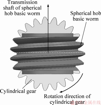
Figure 1 Spherical hob forming principle
The basic worm of spherical hob is distributed on the base sphere, as shown in Figure 2. The angle between ��1 (xnOzn plane) and ��2 (xOz plane) is ��, and this angle is the size of the spiral angle. The plane ��1 and the base sphere intersect to form a base circle, so that the base circle can get the involute P1A and P2B with respect to xn axis symmetry. The intersection point of x axis and the base sphere is P, and PQ is the spherical helix, and the two involutes P1A and P2B rotate around the sphere along the spherical helix to obtain the spherical hob basic worm.
The definition of spherical helix is as shown in Figure 3, when the P point rotates by ��w around the z axis, at the same time it rotates by ��0 around the y axis, ��w and ��0 meet proportional relationship. The synthesis of two rotating motions area spherical helix, and its equation can be represented as:
 (1)
(1)
The lead of the spherical hob basic worm is: when the worm is rotated a circle around the axis of the hob, the point is turned relative to the angle of the spherical center in the end section, that is ��w=2��, ��0 is that we desire.
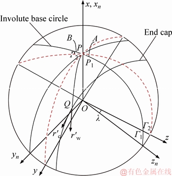
Figure 2 Spherical hob basic worm
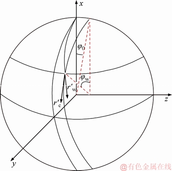
Figure 3 Spherical helix
2.2 Spherical hob basic worm equation
Take the right-handed spherical hob as the research object, the forming coordinate system of its basic worm is shown in Figure 4, where S0 (x0, y0, z0) is the fixed coordinate system, Sn0 (xn0, yn0, zn0) is the auxiliary fixed coordinate system, which is obtained after the coordinate system S0 around the x0-axis rotation angle ��; Sw (xw, yw, zw,) is the moving coordinate system which is connected with the basic worm, and it is corresponding to the coordinate system S0 around the zw-axis rotation angle ��w; Sn (xn, yn, zn) is another moving coordinate system which is connected with cutting tool in the manufacturing process of the traditional spherical hob basic worm, and it is corresponding to the coordinate system Sn0 around the yn-axis rotation ��0 angle, and ��0/��w=Nw/N1. The synthesis of these two rotating motions can obtain the spherical helix, and the involute rotation along the spherical helix can obtain the spherical hob basic worm.
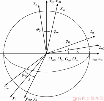
Figure 4 Spherical hob basic worm forming coordinate system
The radial vector function of involute in the coordinate system Sn is expressed as:
 (2)
(2)
where rb is the radius of the cylindrical gear involute base circle; ��0 is the initial angle of the involute; �� is the parameter of the involute.
In Figure 3,  is the tangent vector of the spherical helix;
  is the tangent vector at Q along end section. The angle between the two vectors is the spiral angle of the spherical hob basic worm, and the formula of the vector angle is:
 (3)
(3)
The tangent vector at the end section Q as:
 (4)
(4)
Take the derivative of Eq. (1), we can get the tangent vector of the helix as:
 (5)
(5)
Eqs. (4) and (5) are substituted into Eq. (3), we can obtain:
 (6)
(6)
And
 (7)
(7)
The helix angle ��0 when ��0=0 is defined as the nominal helix angle of the spherical helix, which is the installation angle of the spherical hob processing face gear.
The equation of spherical hob base worm is:
 (8)
(8)
where
 ;
;
 ;
;
 ;
;
Mw,n represents the coordinate transformation matrix from coordinate system Sn to Sw, and it is the product of Mw,0, M0,n0 and Mn0,n.
3 Assembly hob design
3.1 Hob cutter body design
The cutter body is designed in the form of a cylinder. The surface is designed with grooves for mounting the cutter teeth. There are three locating surfaces in the groove, which are used to locate the position of the cutter teeth along the radial, axial and circumferential directions, respectively. It, with the wedge block and end cap together, limits the three mobile degrees of freedom and three rotational degrees of freedom of the tooth. The form of the slot is selected a straight flute according to the direction of the flute. The inclined angle ��0 of the skewed slot is the nominal spiral angle of the spherical spiral, as shown in Figure 6.
3.2 Cutter tooth design
The cutter tooth can be obtained by cutting the standard slotting tool with the pressure angle of from the standard slotting tool. This article selects 20��, the module number of 3.5 mm, the number of teeth of 29 and the nominal index circle diameter of 100 mm. Because the shape of the slotting tool is designed according to the displacement principle, the wire-electrode cutting along the width of the teeth will not affect the tooth profile. Therefore, the proper tooth width of the cutter teeth can be cut out. The multiple teeth can be obtained from a single slotting tool according to reasonable planning.
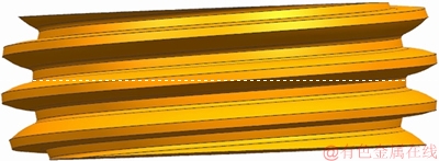
Figure 5 Model of spherical hob basic worm

Figure 6 Spherical hob body design:
The teeth of the spherical hob are regularly arranged along the spherical helix, and the shape of each tooth is different. Assume that there are n rows of teeth on the hob, and each row of teeth is different. Figure 7 shows the difference among each row of teeth on the hob. The angle �� between the centerline of each gear and the bottom edge is different. The difference value between adjacent blades is:
 (9)
(9)
3.3 Whole-assembly
The cutter teeth are assembled in a certain order on the cutter body groove, and the axial position is fixed using the wedge, both ends are fixed with the end cover, the end cover can be pressed on the cutter body by the compression nuts, as shown in Figure 8.
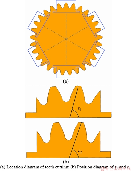
Figure 7 Difference of cutter tooth:
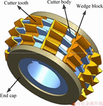
Figure 8 Spherical hob assembly schematic
4 Mathematical model of face gear
4.1 Face gear hobbing machine
Figure 9 shows the structure of the face gear hobbing machine, including three moving shafts (x, y, z) and two rotating axes (B, C). Motion in the x direction is used to achieve radial feed motion. The motion in the y direction is used to achieve axial feed motion. The z-direction motion is used to realize the additional motion of the cutter relative to the face gear. The rotational motion in the B direction is used to realize the rotation of the face gear along its own axis. The rotational motion in the C direction is used to realize the rotation of the cutter around its own axis.
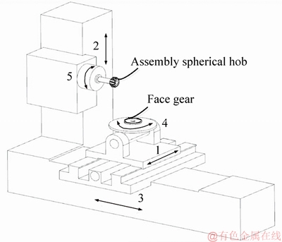
Figure 9 Schematic structure of face gear hobbing machine (1-Axial slide(x); 2-Radial slide(y); 3-Additional slide(z); 4-Work piece axis(B); 5-Spindle axis(C))
4.2 Tooth surface equation of face gear
During the process of gear hobbing, the rotation of the spherical hob simulates the rotation of the spur gear. Meanwhile, in order to process the tooth slot in the direction of the tooth width, it is also necessary to feed in the radial direction of the face gear. Therefore, the hobbing of the face gear is a two-parameter envelope process. Since the hob has a helix angle, the mounting angle corresponding to the helix angle is required for installation. The coordinate system for setting up a hob hobbing machined face gear is shown in Figure 10, where Sh0 (xh0, yh0, zh0) and S20 (x20, y20, z20) are the fixed coordinate system, which represent the initial position of the spherical hob and face gear, respectively. The coordinate system Sh0 is derived from the auxiliary fixed coordinate system Sa (xa, ya, za) around the xa axis rotation ��a. And for the motion coordinate system fixed with the spherical hob and face gear, the rotation angles are respectively satisfied the fixed ratio relationship.
Sh (xh, yh, zh) and S2 (x2, y2, z2) are the auxiliary fixed coordinate system, which are rigidly connected to the spherical hob and face gear, the rotation angles are ��h and ��2, the fixed ratio relationship is:
 (10)
(10)
where Nh=1 and it represents the single-headed spherical hob.
The tooth surface equation of face gear in coordinate system S2 is expressed as:

 (11)
(11)
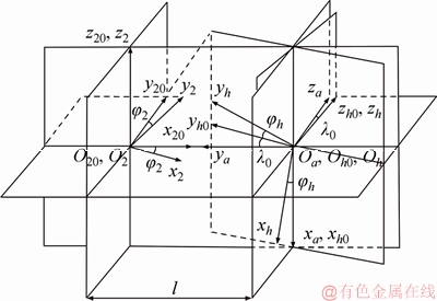
Figure 10 Spherical hob machining face gear coordinate system
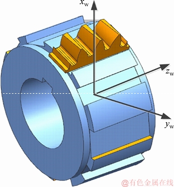
Figure 11 Spherical hob error source
where
 ;
;
 ;
;
 ;
;
 ;
;
M2,h represents the coordinate transformation matrix from coordinate system Sh to S2, and it is the product of M2,20, M20,a, Ma,h0 and Mh0,h; l is the radial motion parameters of the hob. The dual parameter envelope equation of gear hobbing is expressed as:
 (12)
(12)
 (13)
(13)
Equation (12) represents the envelope equation when l is stationary. Equation (13) represents the envelope equation when ��h is stationary.
Simultaneous Eqs. (11), (12), and (13), and limit the rotation angle and the feed amount, the hobbing machined face gear profile can be obtained.
5 Error analysis of spherical hob manufacturing
Assembly error is inevitable during assembly process of spherical hob. Since the rotation of the spherical hob is the rotation of the analog spur gear, the error of the spherical hob can be equivalent to the installation error of the spur gear, such as the similar offset error ��E, the inclined slot angle error ��, the tool radial error ��r and front and back displacement error ��. Figures 12(a) and (b) show these equivalent installation errors.
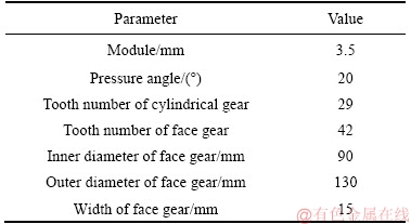
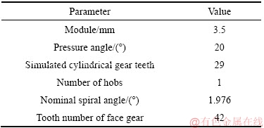
The coordinate systems including equivalent errors ��E, ��, ��r and �� are shown in Figure 12(c). Here, the coordinate system Sh is rigidly connected to the theoretical position of the spherical hob, and Sa, Sb, Sc are the auxiliary coordinate system. The coordinate system Se is the actual position of the spherical hob. Table 1 lists the basic parameters of the face gear.
The tooth surface equation of face gear including the equivalent installation errors in coordinate system S2 is expressed as:

 (14)
(14)
where

 ;
;
 ;
;
 ;
;
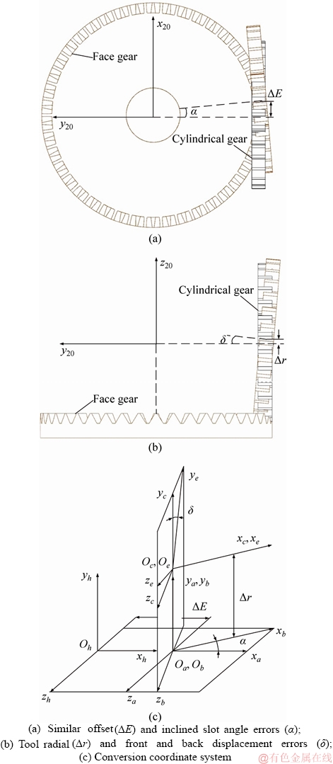
Figure 12 Equivalent cylindrical gear installation error and conversion coordinate system:
For any point H in theoretical tooth surface of face gear, the unit normal vector  and position vector
  are known. The position vector
  of H' points on the actual tooth surface can be measured by means of coordinate measuring machine. The normal direction of the tooth surface in the extension theory is ��H between H and H'.
Table 1 Basic parameters of face gear
The relations among 
 and ��H are presented as:
 (15)
(15)
By solving Eq. (15), the tooth profile error caused by installation error ��E, ��, ��r and �� can be calculated. Similarly, if a tooth profile error is known, the equivalent installation error can be determined.
6 Examples and discussion
The basic parameters of the hob are shown in Table 2. In order to improve the machining accuracy of face gear, the impacts of each type of the above errors are analyzed.
Table 2 Basic parameters of spherical hob
6.1 Tooth profile errors with similar offset errors
Figure 13 shows the tooth profile errors of face gear affected by a similar offset error of ��E. It can be seen that in the inner diameter and outer diameter of the face gear, the tooth profile error affected by similar offset error is different. Figure 13(a) illustrates the tooth profile error of the gear inner diameter.
The tooth surface errors reach the maximum value at the root of the tooth, and then with the increase of the distance from root to top of the face gear, the error decreases gradually and increases at the top of the tooth.
As illustrated in Figure 13(b), the tooth surface errors reach the maximum value at the root of the tooth, and the error decreases gradually with the increase of the distance from root to top of the face gear.
Figure 13 shows the tooth profile errors of face gear affected by a similar offset error of ��E.
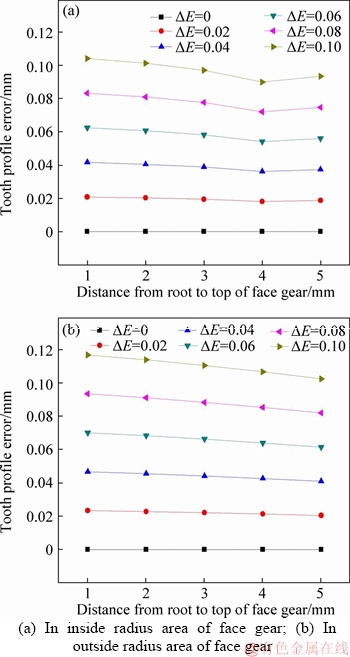
Figure 13 Tooth profile error curves with similar offset errors:
6.2 Tooth profile errors with inclined slot angle errors
Figure 14 shows the tooth profile errors of face gear affected by a similar offset error of ��. The error trend of inner and outer diameter tooth surface under inclined slot angle errors influence is the same as that of similar offset errors. There are differences between the error values and the error range.
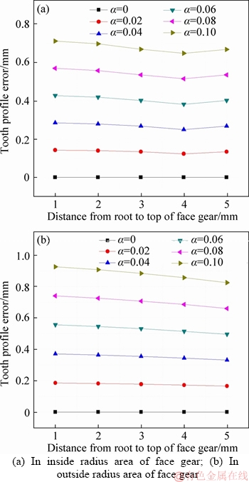
Figure 14 Tooth profile error curves with inclined slot angle errors:
6.3 Tooth profile errors with tool radial errors
Figure 15 shows the tooth profile errors of face gear affected by a similar offset error of ��r. The tooth profile errors at inner diameter of the face gear are illustrated in Figure 15(a). The tooth surface errors reach the minimum value at the root of the tooth, and then with the increase of the distance from root to top of the face gear, the error increases gradually.
As illustrated in Figure 15(b), the tooth surface errors reach the minimum value at the root of the tooth, and the error increases gradually with the increase of the distance from root to top of the face gear.
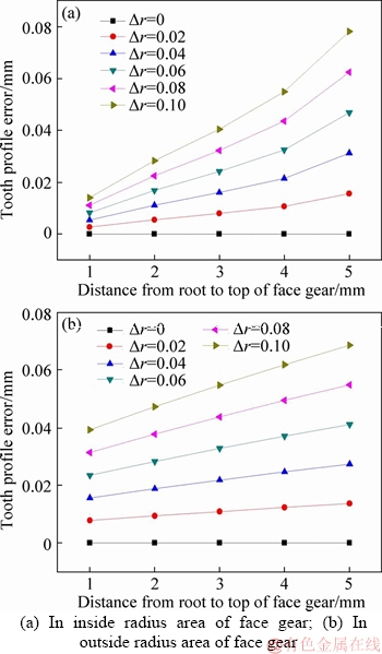
Figure 15 Tooth profile error curves with tool radial errors:
6.4 Tooth profile errors with front and back displacement errors
Figure 16 shows the tooth profile errors of face gear affected by a similar offset error of ��. The error trends of inner and outer diameter tooth surface under front and back displacement errors influence are the same as that of tool radial errors. There are differences between the error values and the error range.
7 Experiments
7.1 Five-axis face gear hobbing machine
According to the generation hobbing principle of face gear, we develop the five-axis face gear hoobing machine, and the schematic structure is shown in Figure 9. The straightness of (x, y, z) direction guide are 0.02 mm/m, 0.03 mm/m and 0.03 mm/m, respectively. The dividing accuracy of B axis is 7 ms, the run out of C axis is 0.01 mm, and the power of spindle motor is 18 kW, as well as the maximum speed of spindle is 1500 r/min. The assembled spherical hob machining process and the assembled hob are shown in Figures 17 and 18, respectively.
7.2 Face gear hobbing experiments
The face gear hobbing experiment is carried out on the developed face gear hobbing machine tool. In the hobbing process, the workpiece speed is 0.2 r/min, the axial feed speed is 2 mm/s, the radial feed speed is 3 mm/s, and the spindle speed is 32 r/min. The hobbing experiment is shown in Figure 19.
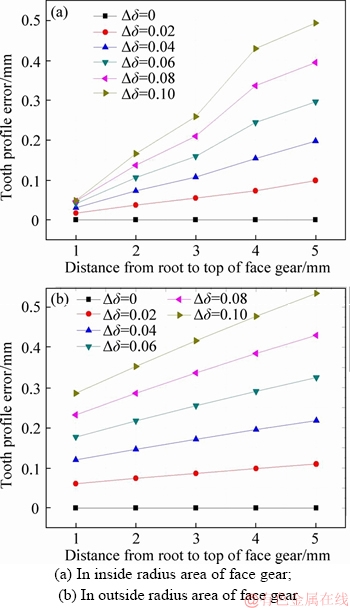
Figure 16 Tooth profile error curves with front and back displacement errors:
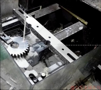
Figure 17 Blade cutting process
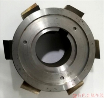
Figure 18��Assembly spherical hob
The tooth surface detection of the face gear is performed by three coordinate measuring machine (CMM), and a tooth surface topological graph is obtained. Figure 20 shows the process of face gear detection by CMM. The tooth surface topological graph after gear hobbing is shown in Figure 21. The maximum deviation is 204.6 ��m, which cannot meet the accuracy need. The error adjustment is needed. According to the error analysis in Section 5, the error amendments for face gear are calculated. The amendments of face gear hobbing processing parameters are shown in Table 3. After the processing parameters are adjusted, a new hobbing machining experiment is performed. The experimental results are shown in Figure 22. The maximum deviation of the tooth surface is 41.3 ��m.
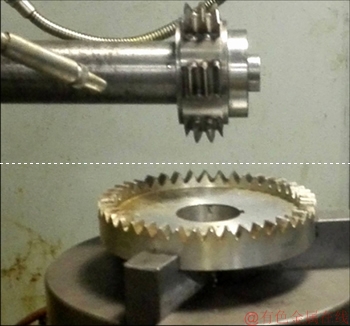
Figure 19 Face gear hobbing machining

Figure 20 Face gear detection process
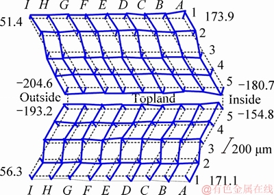
Figure 21 Tooth surface topography before error amendment
Table 3 Machining parameters of face gear
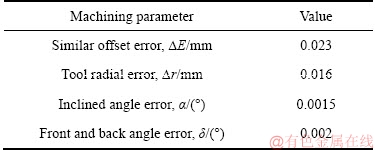
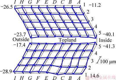
Figure 22 Tooth surface topography after error amendment
8 Conclusions
1) Based on the design principle of spherical hob basic worm, the mathematical model of the spherical hob basic worm is established, which lays a theoretical foundation for the development of the spherical hob.
2) A new method of wire-electrode cutting a standard pinion cutter is used to obtain the hob cutter teeth. A spherical hob base body is developed and the spherical hob assembly is completed. Processing experiments show that the assembled spherical hob can be used for face gear hobbing.
3) A five-axis hobbing machine is developed. Based on the structure of the machine tool, the profile equation of the spherical hob machining face gear is established, and the target tooth surface is provided for the hobbing of face gear.
4) According to the analysis results of spherical hob assembly errors, the influences of each errors are determined, and the errors are corrected in the face gear machining process. The analysis results provide theoretical support for error correction of face gear hobbing process. The error-corrected face gear tooth surface accuracy is significantly improved.
5) The experimental results show that the fabricated spherical hob studied in this paper can achieve precision generation hobbing of face gear.
References
[1] HABIBI M, CHEN Z C. A new approach to blade design with constant rake and relief angles for face-hobbing of bevel gears [J]. Journal of Manufacturing Science & Engineering, 2016, 138(3): 031005.
[2] SHIH Y P, HUANG Y C, LEE Y H, WU J M. Manufacture of face-hobbed straight bevel gears using a six-axis CNC bevel gear cutting machine [J]. International Journal of Advanced Manufacturing Technology, 2013, 68(9-12): 2499-2515.
[3] BODZAS S, DUDAS I. Mathematical description and modeling of a tooth surface of spiroid face gear having arched profile in axial section [J]. International Journal of Advanced Manufacturing Technology, 2016, 84(5-8): 1431-1442.
[4] LIU G Y, WEI W J, DONG X Z, RUI C J, LIU P Y, LI H T. Relief grinding of planar double-enveloping worm gear hob using a four-axis CNC grinding machine [J]. International Journal of Advanced Manufacturing Technology, 2016, 89(9-12): 1-10.
[5] ZHENG F Y, GUO X D, ZHANG M D, ZHANG W Q. Research on the mold release motion for spiral bevel gear forging [J]. International Journal of Mechanical Sciences, 2018, 136(2): 482-492.
[6] SHIH Y P, SUN Z H, WU F C. A disk tool cutting method for bevel gear manufacture on a five-axis machine [J]. International Journal of Advanced Manufacturing Technology, 2018, 94(1): 1-11.
[7] ZHAO N, GUO H, FANG Z D. Research on machining face gears using a CNC hobbing machine [J]. Advanced Materials Research, 2010, 97-101: 3761-3764.
[8] YANG X Y, TANG J Y. Research on manufacturing method of CNC plunge milling for spur face-gear [J]. Journal of Materials Processing Technology, 2014, 214: 3013-3019.
[9] ZANZI C, PEDRERO J I. Application of modified geometry of face gear drive [J]. Computer Methods in Applied Mechanics and Engineering, 2005, 194(27): 3047-3066.
[10] TSAY M F, FONG Z H. Novel profile modification methodology for moulded face-gear drives [J]. Journal of Mechanical Engineering, 2007, 221: 715-725.
[11] CHEN S Y, TANG J Y, CHEN W T, HU Z H, CAO M P. Nonlinear dynamic characteristic of a face gear drive with effect of modification [J]. Meccanica, 2014, 49(5): 1023-1037.
[12] CUI Y M, FANG Z D, SU J Z, FENG X Z, PENG X L. Precise modeling of arc tooth face-gear with transition curve [J]. Chinese Journal of Aeronautics, 2013, 26(5): 1346-1351.
[13] LIN C, FAN Y, ZHANG Z W, FU G, CAO X J. Additive manufacturing with secondary processing of curve-face gears [J]. International Journal of Advanced Manufacturing Technology, 2016, 86(1-4): 1-12.
[14] TANG J, YANG X. Research on manufacturing method of planing for spur face-gear with 4-axis CNC planer [J]. International Journal of Advanced Manufacturing Technology, 2016, 82(5-8): 847-858.
[15] SHEN Y B, LIU X, LI Z P, LI D Y. Research on shaving processing of spiroid face gear [J]. International Journal of Advanced Manufacturing Technology, 2017, 92(1-4): 605-613.
[16] PENG X L, NIU Q Y, GUO W, FANG Z D. A new method of motion rule synthesis for face gear manufacturing by plane-cutter [J]. Journal of Mechanical Design, 2018, 140(2): 023302.
[17] SHEN Y B, LIU X, LI D Y, LI Z P. A method for grinding face gear of double crowned tooth geometry on a multi-axis CNC machine [J]. Mechanism & Machine Theory, 2018, 121: 460-474.
[18] ZHOU Y, TANG J, ZHOU H, YIN F. Multistep method for grinding face-gear by worm [J]. ASME. Journal of Manufacturing Science and Engineering 2016, 138(7): 071013.
[19] WU C H, WANG Y Z. The aeronautics face-gear NC hobbing machining technology [J]. Proceedings of SPIE- The International Society for Optical Engineering. Singapore: ICGIP, 2013: 876828.
[20] WANG Y Z, HOU L W, LAN Z, WU C H, LV Q J, ZHAO X F. A precision generating hobbing method for face-gear based on worm hob [J]. ARCHIVE Proceedings of the Institution of Mechanical Engineers Part C: Journal of Mechanical Engineering Science, 2016, 231(6): 979�C994.
[21] WANG Y Z, HOU L W, LAN Z, ZHU C L. Precision milling method for face-gear by disk cutter [J]. International Journal of Advanced Manufacturing Technology, 2017, 89(5-8): 1-14.
[22] WANG Y Z, LAN Z, HOU L W, ZHAO H P, ZHONG Y. A generating milling method for a spur face gear using a five-axis computer numerical control milling machine [J]. Proceedings of the Institution of Mechanical Engineers Part B: Journal of Engineering Manufacture, 2016, 230(8): 1359-1371.
[23] WANG Y Z, HOU L W, LAN Z, ZHANG G R. Precision grinding technology for complex surface of aero face-gear [J]. International Journal of Advanced Manufacturing Technology, 2016, 86(5-8): 1-10.
[24] WANG Y Z, LAN Z, HOU L W, ZHAO H P, ZHONG Y. A precision generating grinding method for face gear using CBN wheel [J]. International Journal of Advanced Manufacturing Technology, 2015, 79(9-12): 1839-1848.
[25] WANG Y Z, LAN Z, HOU L W, CHU X M, YIN Y Y. An efficient honing method for face gear with tooth profile modification [J]. International Journal of Advanced Manufacturing Technology, 2017, 90(1-4): 1155-1163.
(Edited by HE Yun-bin)
���ĵ���
һ��װ��ʽ���ι����ӹ�����־���չ�ɹ��ݷ���
ժҪ��Ϊ���������ּӹ����Ⱥ����̹��ݼӹ����ڣ����������һ��װ��ʽ���ι����ӹ�����־���չ�ɹ��ݷ�������һ��������Բ�����������ι������ϸ��ݱ��������������ι������ϸˣ����������ι������ϸ˺������߷��̡��ڶ����������еĹ�����Ʒ�����������װ��ʽ���ι������Ʒ����������װ��ʽ���ι������ݺͻ��壬���������װ�䡣��������������ֹ��ݼӹ����������˹��ݼӹ����ػ���������������ֳ��淽�̡����ģ�Ϊ�˼����ɵ�Ч��װ������������ּӹ���������������ģ�ͣ������˸���������ֳ����Ӱ�졣�����������ι���װ�������ֹ������顣���ݲ����������������ֹ��ݼӹ�����������ƫ��õ��������͡�
�ؼ��ʣ�����֣����ι������ϸˣ�װ��ʽ���ι����������������ݼӹ�
Foundation item: Project(9140xx8020212xx) supported by the Advanced Research Foundation, China; Project(GZ2018KF003) supported by the State Key Laboratory of Smart Manufacturing for Special Vehicles and Transmission System, China
Received date: 2018-05-06; Accepted date: 2019-03-01
Corresponding author: CHU Xiao-meng, PhD; Tel: +86-10-82339035; E-mail: cthzym@buaa.edu.cn; ORCID: 0000-0002-2322-6067

