
J. Cent. South Univ. (2018) 25: 1862-1869
DOI: https://doi.org/10.1007/s11771-018-3875-8

Investigation of modeling on single grit grinding for martensitic stainless steel
NIE Zhen-guo(聂振国)1, 2, 3, WANG Gang(王罡)1, 2, JIANG Feng(姜峰)4,LIN Yong-liang(林永亮)5, RONG Yi-ming(融亦鸣)1, 2, 6
1. State Key Laboratory of Tribology & Institute of Manufacturing Engineering, Department of Mechanical Engineering, Tsinghua University, Beijing 100084, China;
2. Beijing Key Laboratory of Precision/Ultra-precision Manufacturing Equipments and Control, Tsinghua University, Beijing 100084, China;
3. Mechanical Engineering Department, Carnegie Mellon University, Pittsburgh, PA 15213, USA;
4. College of Mechanical Engineering and Automation, Huaqiao University, Xiamen 361021, China;
5. School of Mechanical Electronic and Control Engineering, Beijing Jiaotong University,Beijing 100044, China;
6. Mechanical and Energy Engineering Department, South University of Science and Technology of China,Shenzhen 518055, China
 Central South University Press and Springer-Verlag GmbH Germany, part of Springer Nature 2018
Abstract: Single grit grinding is the simplified model to abstract the macro scale grinding. Finite element analysis is a strong tool to study the physical fields during a single grit grinding process, compared to experimental research. Based on the dynamic mechanical behavior of 2Cr12Ni4Mo3VNbN steel and the mathematical statistics of abrasive grit, modeling of the single grit grinding process was conducted by using commercial software AdvantEdge. The validation experiment was designed to validate the correctness of the FEA model by contrast with grinding force. The validation result shows that the FEA model can well describe the single grit grinding process. Then the grinding force and multi-physics fields were studied by experimental and simulation results. It was found that both the normal and tangential grinding forces were linearly related to the cutting speed and cutting depth. The maximum temperature is located in the subsurface of the workpiece in front of the grit, while the maximum stress and strain are located under the grit tip. The strain rate can reach as high as about 106 s–1 during the single grit grinding,which is larger than other traditional machining operations.
Key words: modeling; single grit grinding; grinding force; multi-physics; martensitic stainless steel
Cite this article as: NIE Zhen-guo, WANG Gang, JIANG Feng, LIN Yong-liang, RONG Yi-ming. Investigation of modeling on single grit grinding for martensitic stainless steel [J]. Journal of Central South University, 2018, 25(8): 1862–1869. DOI: https://doi.org/10.1007/s11771-018-3875-8.
1 Introduction
Steam turbine and gas turbine are the most common thermal turbo machinery system. Grinding process is generally used as the final machining method to manufacture the turbine blades due to high precision and good surface quality. For 1000 MW steam turbine made by Dongfang Steam Turbine Works (DFSTW), the last rotor blades are made of 2Cr12Ni4Mo3VNbN steel, which is a martensitic stainless steel [1]. Grinding burn is a common phenomenon and problem in creep feed grinding of turbine blades [2]. The evolutions of the temperature field, stress and strain fields during material removal process are the theoretical foundation for establishing the technological parameters of grinding [3].
Unlike the metal cutting, the material removal process in grinding is hardly observed directly [4]. Single grit grinding is an equivalent study method instead of real macro scale grinding [5, 6]. Numerical simulation and experimental study are the two important tools to study the material removal mechanism of a single grit grinding process [7–9]. Single grit grinding process could be used to model the equivalent heat source of macro scale grinding [10], and provides theoretical basis for abrasive wheel design [11].
Grit shape has a significant effect on the material removal rate. It was found that the sharper grit can get a high grinding efficiency [12]. Cutting force in single grit grinding was studied by many scholars [5, 13]. Chip formation was based on the critical cutting depth [14].
In this work, mechanical finite element modeling of the single grit grinding process was established based on the analysis of abrasive grit micro-topography and the dynamic mechanical behavior of the material. Then the validation experiment was conducted to validate the mechanical model by comparing the grinding force. The grinding force, temperature field, and stress– strain field were studied on the basis of the results of the finite element analysis.
2 Modeling of single grit grinding process
The interaction between the abrasive-grit and workpiece during the grinding process is a complicated movement. Two critical depths δr and δp divide the motion into three stages of material removal [15], as shown in Figure 1. When 0<αp<δr, the grit rubs on the workpiece. Elastic deformation occurs without any material removal. Plowing occurs as the cutting depth increases to the range of δr<αp<δp. Plastic and elastic deformations both occur and a plowed groove appears. Cutting occurs when the depth increases to the range of δp<αp<δc and a chip will be expelled. Material removal occurs only in the cutting stage. The mechanism of cutting stage plays an important role in the surface integrity after grinding.
2.1 Mathematical statistics of abrasive grits
The discrete abrasive grits randomly distribute on the grinding wheel surface. The mechanism of action between the abrasive grits and workpiece is quite complex. Mathematical statistics of the abrasive grits were used to get the geometric parameters of the equivalent grit.
Because of its characteristic of economy and usability, alumina wheel is widely used in the creep feed grinding of turbine blades. As shown in Figure 2, the micro-topography of a white fused alumina wheel (WA400×30×127A80L5V35) was measured by the white-light interferometer. The abrasive grit can be equivalent to a ball-end cone, as shown in Figure 3. Cone angle and nose radius are used to describe the geometrical characteristics. Distribution density, average spacing and protrusion height are used to describe the distribution characteristics. The statistical results are listed in Table 1 by FFT method [16].
2.2 Geometric model and technological parameters
As shown in Figure 4, x-axis is the direction of grit travel, y-axis is the normal direction of the scratched surface, and z-axis is the landscape direction. The dimensions of the workpiece are 0.5 mm length, 0.6 mm width and 0.3 mm height. Simulations would be conducted respectively using diamond grit and alumina grit (Table 2). The simulation with diamond grit is for validation of the FEA model, while the simulation with alumina grit is to study the evolution of multi-physics fields during the real grinding process of steam turbine. It is extremely difficult to manufacture a regular shape from alumina. The diamond grit will be used instead of alumina in the validation experiment.
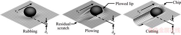
Figure 1 Three stages of single grit grinding [15]
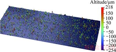
Figure 2 Micro-topography of abrasive wheel surface
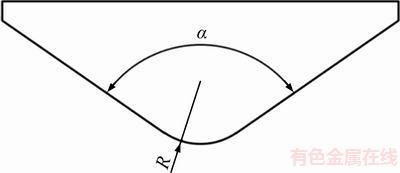
Figure 3 Equivalent ball-end cone of abrasive grit
Table 1 Statistical parameters of abrasive grit
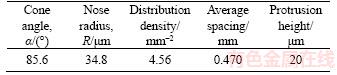
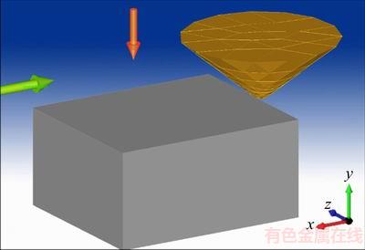
Figure 4 Geometrical model of single grit grinding
2.3 Dynamic mechanical behavior of 2Cr12Ni4Mo3VNbN steel
The workpiece is made of tempered 2Cr12Ni4Mo3VNbN steel. 2Cr12Ni4Mo3VNbN steel is a martensitic stainless steel which is widely used in manufacturing steam turbine blades due to its excellent corrosion resistance. The chemical composition of the 2Cr12Ni4Mo3VNbN steel is listed in Table 3. Chromium and nickel can improve the corrosion resistance in an oxidizing medium. Molybdenum can improve the corrosion resistance in non-oxidizing acid and alkaline solutions. Titanium and niobium form stable carbides with carbon poor chrome.
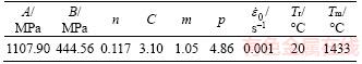
Johnson-Cook (JC) model is frequently used to describe the dynamic mechanical behavior in the simulation of the metal cutting process. JC model is a strain rate and temperature-dependent visco- plastic material model which explains the relationship between stress, strain, strain rate and temperature [17]. At high strain rate, the JC model cannot predict the flow stress well [18, 19]. A modified Johnson-Cook model is used as a good fitness when the strain rate varies over a large range (102 to 106 s–1) [20]. The model is expressed in Eq. (1).
 (1)
(1)
 (2)
(2)
 (3)
(3)
where A, B, n, C, p and m are material constants; A is the yield strength (MPa); B is the hardening modulus (MPa); n is the hardening coefficient; C and p are the strain rate sensitivity coefficients; m is the thermal softening coefficient; is a dimensionless parameter;
 is the strain rate;
 is the reference strain rate; Tr is the reference temperature and Tm is the melting temperature of the material. For 2Cr12Ni4Mo3VNbN steel, all the parameters in the modified Johnson-Cook are listed in Table 4.
3 Experimental design and validation
An experiment of single grit grinding was designed and conducted to validate the accuracy of the finite element model and the reliability of the computed result. Grinding force during the single grit grinding process was measured to compare the computed value.
Table 2 Technological parameters of numerical simulation

Table 3 Chemical composition of 2Cr12Ni4Mo3VNbN steel (wt%)
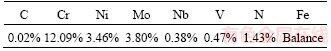
Table 4 Parameters of modified Johnson-Cook model for 2Cr12Ni4Mo3VNbN steel
3.1 Experimental design of single grit grinding
The experiment of single grit grinding was conducted on a high precision NC lathe (HTC4169a). The schematic diagram of the experiment is presented in Figure 5. The workpiece was manufactured into a thin-walled cylinder with the external diameter of 400 mm, the wall thickness of 10 mm, and the height of 100 mm. The workpiece was fixed onto the lathe chuck, as presented in Figure 6. The diamond grit was welded in the holder, as shown in Figure 7. Kistler 5080 dynamometer was used to measure the grinding force in three orientations. Force signal was acquired by the data acquisition system (DAS). The nose radius of the grit ball-end was measured by a high-power microscope before each test, as shown in Figure 8.
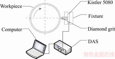
Figure 5 Schematic diagram of single grit grinding experiment
The diamond grit was manufactured with the dimension in Figure 3 and Table 1. Diamond grit was used as the cutting tool due to its good workability compared to alumina. Diamond also has its weakness, which has a large chemical affinity with iron atoms. It results in severe wear of diamond with the steel workpiece in the grinding process. The diamond grit needs to be replaced once worn seriously.
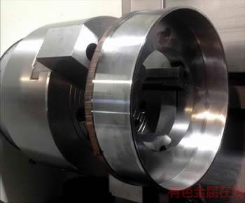
Figure 6 Thin-walled cylinder workpiece
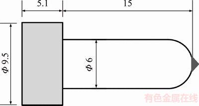
Figure 7 Grit holder (Unit: mm)
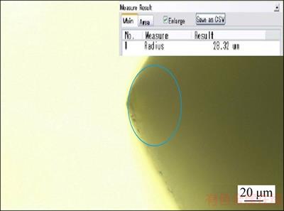
Figure 8 Measurement of grit ball-end
3.2 Grinding force in single grit grinding process
Figures 9 and 10 show the variation of grinding force changing with cutting speed and cutting depth. With the increase of the cutting speed and cutting depth, both normal force (y direction) and tangential force (x direction) increase linearly. Increasing cutting depth, the plastic deformation and material removal will both increase, which would result in an increase in grinding force.
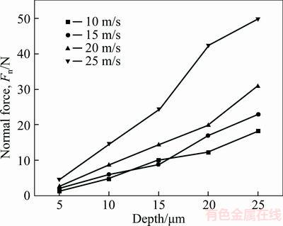
Figure 9 Variation of normal grinding force
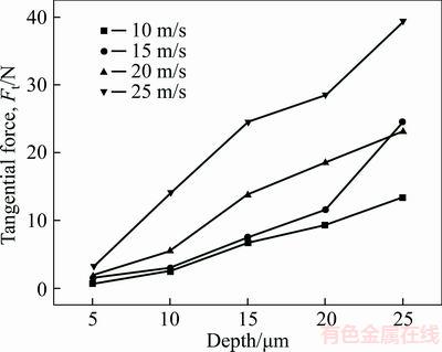
Figure 10 Variation of tangential grinding force
Increasing cutting speed, the strain rate hardening effect would result in an increase in grinding force as well. The fitting equations of single grit grinding forces are listed as below.
 (4)
(4)
 (5)
(5)
where Fn is the normal force; Ft is the tangential force; ap is cutting depth; and vs is the cutting speed. an=0.8413, βn=0.9567, αt=0.6331, βt=1.182 are all the fitting coefficients.
3.3 Validation of FEA model
Three components of grinding force in the three orthogonal directions during a single grit grinding process with a constant cutting-depth were computed by the FEA model, as presented in Figure 11. It can be seen that the grinding forces basically remain unchanged during the cutting process. The experimental results and simulation results are compared in Figure 12. Tangential force and normal force were both computed and measured. It can be seen that the grinding force increases with the cutting depth. The relative error between simulation results and experimental results is under 10% when the cutting depth is less than 15 μm. But the experimental values are obvious below the simulation values when the cutting depth is larger than 20 μm. Large cutting depth will generate more heat, and then the diamond grit wears seriously. The real cutting depth will be smaller than the desired value. Based on the above analysis, the FEA model can predict the grinding forces effectively.
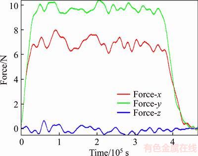
Figure 11 Simulated single grit grinding forces (vs=10 m/s, ap=15 μm)
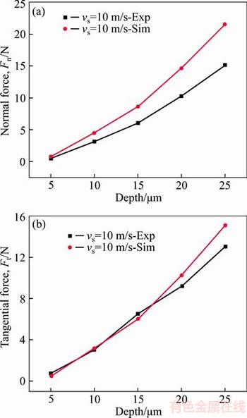
Figure 12 Comparison of grinding force between experimental and simulation results
4 Simulation results and discussion
Multi-physics fields (including temperature, stress, strain, etc.) of the single grit grinding process cannot be acquired by experimental measurement due to small affected zone and rapid motion of the grit. The numerical simulation method is a useful tool to solve the problem.
4.1 Temperature field
As shown in Figure 13, the temperature field was computed in a certain technological condition in which cutting speed is 10 m/s and cutting depth is 15 μm. The maximum temperature is about 639.17 °C which is located in the subsurface of the workpiece in front of the grit, rather than the outside surface. The temperature of the outside surface in front of the grit is just about 300 °C. The workpiece material in front of the grit is in the shear band. The deformation heat makes the temperature increase, and the maximum heating rate may reach about 106 W/mm3 (Figure 14). Due to the extremely high conductive capacity of diamond, heat transfers from the outside surface of the workpiece to the diamond. The temperature of the outside surface will be lower than the temperature of the subsurface.
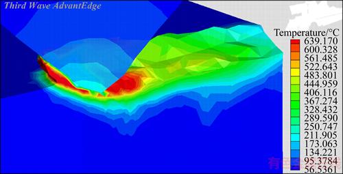
Figure 13 Temperature field by symmetrical ross-section (vs=10 m/s, ap=15 μm)
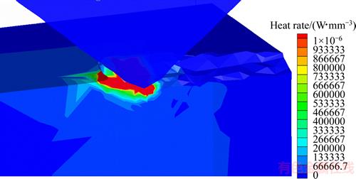
Figure 14 Heat rate field (vs=10 m/s, ap=15 μm)
Figure 15 shows the variation of the maximum temperatures with cutting speed and depth. It can be seen that the increase in cutting speed and depth will result in the increase in the maximum temperature. The maximum temperature can exceed the phase transformation temperature of the steel (austenitizing temperature) when the cutting speed and depth are larger than some certain values.
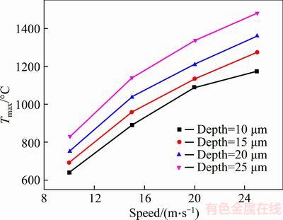
Figure 15 Variation of maximum temperature with cutting speed and depth
4.2 Stress and strain fields
Mises stress filed during grinding process is presented in Figure 16. The maximum Mises flow stress of the workpiece material is located under the grit tip, with a maximum stress 1000 MPa. Mises stress of machined surface is about 400 MPa which is less than the region under the grit. Figures 17 and 18 show the residual stress respectively along x and z directions. It can be seen that both the two directions have the residual compressive stress after single grit grinding. Figure 19 shows the residual stress distribution of x and z direction along y-axis after macroscale grinding. Macroscale grinding includes numerous passes of single grit grinding with the same cutting speed but diverse cutting depth. Both the single grit grinding and macro scale grinding have compressive stress on the machined surface.
As presented in Figure 20, the maximum plastic strain of the workpiece material is located under the grit tip, which is in the same position as Mises stress. As a result of the rapid movement of grit, the strain rate can reach as high as about 106 s–1(Figure 21). Strain rate hardening effect will play an important role to enlarge the plastic flow stress under such great strain rate.
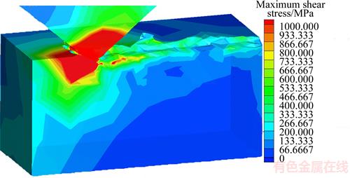
Figure 16 Mises stress field during grinding (vs=10 m/s, ap=15 μm)
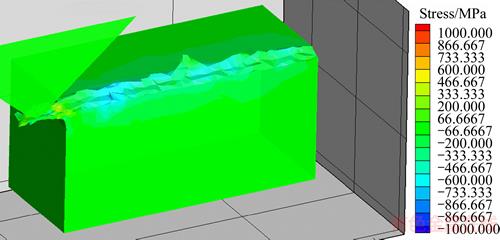
Figure 17 Residual stress field of x direction (vs=10 m/s, ap=15 μm)
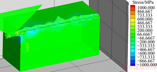
Figure 18 Residual stress field of z direction (vs=10 m/s, ap=15 μm)
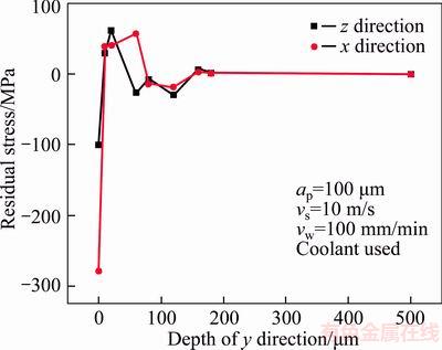
Figure 19 Residual stress distributions after macro scale grinding (Experimental condition: 2Cr12Ni4Mo3VNbN steel, fused alumina wheel (WA400×30×127A80L5V35), grinding depth 100 μm, speed of grinding wheel 10 m/s, feed rate 100 mm/min)
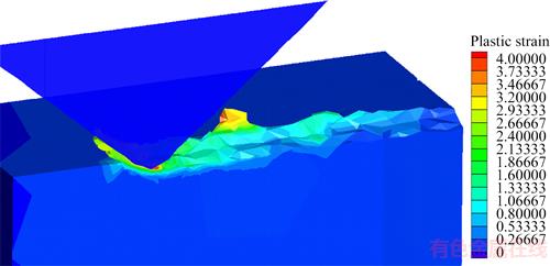
Figure 20 Strain field (vs=10 m/s, ap=15 μm)
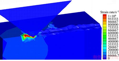
Figure 21 Strain rate field (vs=10 m/s, ap=15 μm)
5 Conclusions
Modeling and simulation of the single grit grinding process were conducted in AdvantEdge software. The accuracy and precision of the FEA model were validated well by experiments with comparison the grinding force. Both the normal force and tangential force have a linear relationship with cutting speed and cutting depth. The empirical equations were fitted to describe the grinding force.
The maximum temperature is located in the subsurface of the workpiece in front of the grit but not the outside surface. The maximum temperature can exceed the phase transformation temperature of the steel when the cutting speed and depth are larger than some certain values.
The maximum Mises stress and plastic strain of workpiece material are located under the grit tip. Both the single grit grinding and macro scale grinding perform compressive stress on the machined surface. The maximum strain rate can reach as high as about 106 s–1 during the single grit grinding process. High strain rate will enlarge the plastic flow stress.
References
[1] NIE Zhen-guo, WANG Gang, YU Jian-chao, RONG Yi-ming. Dynamic mechanical behavior and phase-based constitutive model of 20Cr12Ni4Mo3VNiN in austenitizing stage [C]// TMS 2014 Supplemental Proceedings. 2014: 1125–1131. DOI: https://doi.org/ 10.1007/978-3-319-48237-8_134.
[2] MALKIN S, GUO C. Thermal analysis of grinding [J]. CIRP Annals-Manufacturing Technology, 2007, 56(2): 760–782. DOI: https://doi.org/10.1016/j.cirp.2007.10.005.
[3] KIM H J, KIM N K, KWAK J S. Heat flux distribution model by sequential algorithm of inverse heat transfer for determining workpiece temperature in creep feed grinding [J]. International Journal of Machine Tools and Manufacture, 2006, 46(15): 2086–2093. DOI: https://doi.org/10.1016/ j.ijmachtools.2005.12.007.
[4] DOMAN D A, WARKENTIN A, BAUER R. Finite element modeling approaches in grinding [J]. International Journal of Machine Tools and Manufacture, 2009, 49(2): 109–116. DOI: https://doi.org/10.1016/j.ijmachtools.2008.10.002.
[5] GORANA V K, JAIN V K, LAL G K. Forces prediction during material deformation in abrasive flow machining [J]. Wear, 2006, 260(1, 2): 128–139. DOI: https://doi.org/ 10.1016/j.wear.2004.12.038.
[6] BARGE M, RECH J, HAMDI H, BERGHEAU J M. Experimental study of abrasive process [J]. Wear, 2008, 264(5, 6): 382–388. DOI: https://doi.org/10.1016/j.wear. 2006.08.046.
[7] OUMLPOUMLZ T T, CHEN X. Single grit grinding simulation by using finite element analysis [J]. AIP Conference Proceedings, 2011, 1315(1): 1467–1472. DOI: https://doi.org/10.1063/1.3552394.
[8] AURICH J C, KIRSCH B. Kinematic simulation of high-performance grinding for analysis of chip parameters of single grains [J]. CIRP Journal of Manufacturing Science and Technology, 2012, 5(3): 164–174. DOI: https://doi.org/ 10.1016/j.cirpj.2012.07.004.
[9] ZHU D, YAN S, LI B. Single-grit modeling and simulation of crack initiation and propagation in SiC grinding using maximum undeformed chip thickness [J]. Computational Materials Science, 2014, 92: 13–21. DOI: https://doi.org/ 10.1016/j.commatsci.2014.05.019.
[10] NIE Zhen-guo, WANG Gang, LIU De-hao, RONG Yi-ming (Kevin). A statistical model of equivalent grinding heat source based on random distributed grains [J]. Journal of Manufacturing Science and Engineering, 2017, 140(5): 051016. DOI: 10.1115/1.4038729.
[11] NADOLNY K,  W. Design of a device for precision shaping of grinding wheel macro- and micro- geometry [J]. Journal of Central South University, 2012, 19(1): 135–143. DOI: https://doi.org/10.1007/s11771-012- 0982-9
[12]  PZ T T, CHEN X. Experimental investigation of material removal mechanism in single grit grinding [J]. International Journal of Machine Tools and Manufacture, 2012, 63: 32–40. DOI: https://doi.org/10.1016/j.ijmachtools.2012.07.010.
[13] WANG H, SUBHASH G, ABHIJIT CHANDRA A. Characteristics of single-grit rotating scratch with a conical tool on pure titanium [J]. Wear, 2001, 249(7): 566–581. DOI: https://doi.org/10.1016/ S0043-1648(01)00585-3.
[14] BUTLER-SMITH P W, AXINTE D A, DAINE M. Solid diamond micro-grinding tools: From innovative design and fabrication to preliminary performance evaluation in Ti–6Al–4V [J]. International Journal of Machine Tools and Manufacture, 2012, 59: 55–64. DOI: https://doi.org/10.1016/ j.ijmachtools.2012.03.003.
[15] ANDERSON D, WARKENTIN A, BAUER R. Experimental and numerical investigations of single abrasive-grain cutting [J]. International Journal of Machine Tools and Manufacture, 2011, 51(12): 898–910. DOI: https://doi.org/10.1016/ j.ijmachtools.2011.08.006.
[16] YAN Lan. Research on grinding mechanism of hardened cold-work die steel based on single grain cutting [D]. Changsha: Hunan University, 2010. (in Chinese)
[17] JOHNSON G R, COOK W H. A constitutive model and data for metals subjected to large strains, high strain rates and high temperatures [C]// Proceedings of the 7th International Symposium on Ballistics. 1983: 541–547. Article ID: 10030415477.
[18] GAO C Y, ZHANG L C. Constitutive modelling of plasticity of fcc metals under extremely high strain rates [J]. International Journal of Plasticity, 2012, 32: 121–133. DOI: https://doi.org/10.1016/j.ijplas.2011.12.001.
[19] WANG Xiang-yu, HUANG Chuan-zhen, ZOU Bin, LIU Han-lian, ZHU Hong-tao, WANG Jun. Dynamic behavior and a modified Johnson-Cook constitutive model of Inconel 718 at high strain rate and elevated temperature [J]. Materials Science and Engineering A–Structural Materials Properties Microstructure and Processing, 2013, 580: 385–390. DOI: https://doi.org/10.1016/j.msea.2013.05.062.
[20] NIE Zheng-guo, WANG Gang, YU Jian-chao, LIU De-hao, RONG Yi-ming. Phase-based constitutive modeling and experimental study for dynamic mechanical behavior in martensitic stainless steel under high strain rates in a thermal cycle [J]. Mechanics of Materials, 2006, 101: 160–169. DOI: https://doi.org/10.1016/j.mechmat.2016.08.003.
(Edited by YANG Hua)
中文导读
马氏体不锈钢单磨粒磨削过程的建模研究
摘要:单磨粒磨削是宏观尺度磨削的简化模型。相比于传统实验研究,有限元分析是一种强有力的研究工具,可以计算得到单磨粒磨削过程的多物理场分布。本文基于2Cr12Ni4Mo3VNbN不锈钢的动态力学模型和磨粒的数学统计模型,使用AdvantEdge软件对单磨粒的磨削过程进行了有限元建模,计算得到了磨削温度场、应力应变场、磨削力等物理量。搭建了单磨粒磨削试验平台,测量了不同工艺参数下的磨削力变化。通过对比磨削力的实验值和计算值,结果表明有限元模型可以较好地描述单磨粒磨削过程。试验和仿真数据一致表明,法向磨削力和切向磨削力均与磨粒的切速、切深成正比;工件的最大磨削温度位于磨粒前刃面的下方,而应力应变最大值则位于磨粒尖端的下方。单磨粒磨削过程的应变变形率高达106 s–1,远超其他常规切削方式的应变变形率。
关键词:建模;单磨粒磨削;磨削力;多物理场;马氏体不锈钢
Foundation item: Projects(U1537202, 51575305) supported by the National Natural Science Foundation of China; Project(61328302) supported by National Security Major Basic Research Program of China
Received date: 2016-03-02; Accepted date: 2016-06-06
Corresponding author: WANG Gang, PhD, Associate Professor; Tel: +86-10–62794751; E-mail: gwang@tsinghua.edu.cn; ORCID: 0000-0001-6330-1319

