
FEM equivalent model for press bend forming of aircraft integral panel
YAN Yu(阎 昱), WAN Min(万 敏), WANG Hai-bo(王海波)
School of Mechanical Engineering and Automation, Beihang University, Beijing 100083, China
Received 12 May 2008; accepted 28 August 2008
Abstract: An original plastic equivalent model was proposed to solve the problem of excessive FEM simulation time when designing the press bend forming path and optimizing the process parameters of press bend forming of the integrally stiffened aircraft panels. Based on the in-depth analysis of the mechanics of the bending and springback of the detailed model and the equivalent model of the integral panels, the plastic equivalent model of the virtual material with special initial yield stress and hardening coefficients was constructed. FEM results indicate that the objective of getting the similar contour with the same press bend forming path is achieved with the error less than 6%, and the efficiency of FEM simulation is improved by more than 80%. The plastic equivalent model is valuable and essential for the further research on the press bend forming process of large scale complicated integral panels.
Key words: equivalent model; integrally stiffened panel; press bend forming; plastic equivalent plate; virtual material parameters
1 Introduction
Because of the light mass, high stiffness, and high structural efficiency, integrally stiffened aircraft panels are widely used[1]. Press bend forming is a traditional forming method used in the aircraft manufacturing. This forming method has many advantages, such as low tooling cost, short cycle time and adaptability to different contours[2]. Based on the discontinuous three-point bending principle, press bend forming process performs multi-step bending with universal dies according to planned path. The critical factor that forms the contours of the integral panel is the press bend forming path, which includes the bending position and the punch displacement. So, designing the proper press bend forming path is the key problem in the press bend forming process.
In order to improve the forming quality, FEM simulation is often adopted to design the press bend forming path to replace the time consuming and costly “trial and error” method. Establishment of the reliable FE model is the key point for studying the complex forming process[3-4]. However, there are several difficulties in the FEM analysis of press bend forming process of the aluminium alloy integral panel of aircraft. Firstly, the dimensions of the integral panel of the new generation aircraft are quite large, and the stiffeners are tall and complicated, which lead to tremendous meshing and calculating time. Secondly, this multi-step forming process consists of multiple times of bending and springback. Implicit algorithm is adopted to achieve higher accuracy and avoid transferring between explicit and implicit algorithms, but the complicated contact condition may lead to convergence problems. So, it is almost impossible to optimize the press bend forming path with multiple times of FEM simulation if the detailed model of the integral panel is adopted. And it is essential to create an equivalent model for the press bend forming of the integrally stiffened panel to improve the efficiency of FEM simulation and process optimization.
Many researchers have studied and developed some elastic equivalent models for the stiffened plates, the honeycomb sandwich plates and the corrugated plates. In 1938, HUBER proposed an equivalent slab of constant thickness having the same stiffness characteristic as the stiffened slab, which is called “method of elastic equivalence”[5]. Since then, many researchers carried out some further experiments and developed HUBER’s theory[6-9]. Recently, BRADLEY[10-11] and MUKHOPADHYAY[12] brought forward an equivalent thickness model with the elastic modulus obtained from the bending stiffness and orthogonal characteristics of the detailed model to replace integral panels. Similarly, the equivalent mechanical parameters of the honeycomb sandwich plates[13-16] and the corrugated plates[17-18] were obtained with mechanical analyses of the elastic properties, and many equivalent models were proposed and validated with the FEM simulation[19-20]. But all of these equivalent models are applicable only to the elastic deformation stage, while press bend forming is based on plastic deformation. To create an equivalent model for this forming process, plastic properties of the metal need to be considered. But no equivalent model in view of plastic properties has been reported yet.
In this study, the press bending and springback processes were analyzed thoroughly. According to the demand of the press bend forming path with FEM simulation, a virtual material model was constructed by strict mechanical derivation, and an original plastic equivalent model for the press bend forming of integrally stiffened panel was developed to improve the FEM calculation efficiency. To verify the reliability of the equivalent model, FEM simulations were carried out on both the detailed model and the equivalent model. The key problem of the FEM analysis of the press bend forming process was solved, and a good foundation of the process optimization was laid.
2 Establishment of equivalent model
Assuming that no stiffener buckling and cracking occurs, the goal of developing the equivalent model is to get the similar contours as the detailed model with less modelling and calculating time in designing the press bend forming path, which is the key problem of press bend forming. After the press bend forming path is decided, further research on the local part of the detailed model will be carried out to prevent the occurrence of the stiffener buckling and cracking. As stated before, an elastic equivalent model is not applicable in press bend forming analysis. It is necessary to analyze thoroughly the plastic deformation mechanics and construct a virtual material with special plastic characteristics to develop the equivalent model. A plastic equivalent plate was proposed to be the plastic equivalent model. Plastic equivalent plate is made of a virtual material that forms the similar contour as the detailed model when being formed with the same press bend forming path. The thickness of the plastic equivalent plate is the same as the sum of the stiffener height and the skin thickness of the detailed model, and the width of the equivalent plate is the same as the skin width of the detailed mode, which ensures the same contours of two models before forming and the convenience of contrasts of the contours after forming.
2.1 Springback of plastic equivalent plate
Press bend forming is actually a three point bending. When the punch displacement is rather small, the bending radius of the inner surface is extremely large, and the material deforms elastically. With lowering down the punch, the inner surface wraps around the punch, and the bending radius of the inner surface becomes the same as the radius of the punch[21-22], as shown in Fig.1.

Fig.1 Press bending deformation process: (a) Extremely large bending radius stage; (b) Local wrap-around stage
When choosing the section of the plastic equivalent plate that wraps around the punch as the investigation object, the contours before and after springback are shown in Fig.2. L1 and L2 are the arc lengths of the inner and outer wraps around section before springback, respectively;  and
and  are the arc lengths of the inner and outer wraps around section after springback, respectively; α1 and α2 are the bending angle of the wrap around section before and after springback, respectively; R1E and R2E are the bending radii of the outer surfaces of the plastic equivalent plate before and after springback, respectively; and t is the thickness of the plastic equivalent plate.
Before springback, the ratio of the outer arc length to inner arc length is
 (1)
(1)
After springback, the bending radius of the inner surface of the plastic equivalent plate becomes larger, while the bending angle becomes smaller. The inner and outer arc lengths of the wrap around section are as follows:
 (2)
(2)
 (3)
(3)
where  and
and  are the tangential strains of the inner and outer surfaces of the wrap around section caused by springback, respectively.

Fig.2 Contours before and after springback: (a) Before springback; (b) After springback
The ratio mentioned above can also be expressed as
 (4)
(4)
From Eq.(1) and Eq.(4),
 (5)
(5)
Thus, the bending radius of the outer surface of the plastic equivalent plate after springback is

 (6)
(6)
where σ1E and σ2E are the inner and outer normal bending stresses of the plastic equivalent plate before springback.
≤
The relation between the strain and the stress of the material can be calculated with the following formula [23]:
 (7)
(7)
where σ is the true stress; E is the elastic modulus; ε is the true strain in the elastic deformation stage; σs is the initial yield stress; εP is the plastic strain; K is the hardening coefficient; and n is the hardening exponent.
Assume that the stress condition of the bending is linear, namely only the normal bending stress works and the other two major stress components are ignored. This may greatly simplify the derivation without too much error, and can meet the demand of the engineering analysis[24-25]. In the plastic deformation stage, the true strain is the sum of the elastic strain and the plastic strain. Assuming that the position of the neutral surface does not change during bending and springback stages, with Eq.(7), the normal bending strain of the inner and outer surface before springback can be expressed as
 (8)
(8)
 (9)
(9)
where ε1E and ε2E are the normal bending strains of the inner and outer surfaces of the plastic equivalent plate before springback, respectively; σsE is the initial yield stress of the virtual material of the plastic equivalent plate; nE is the hardening exponent of the virtual material of the plastic equivalent plate; and KE is the hardening coefficient of the virtual material of the plastic equivalent plate.
2.2 Springback of single stiffener specimen
Taking the I-section specimen as an example, the dimensions are shown in Fig.3. The neutral surface of bending is also assumed to stay at the same position, which is represented by “Zc” in Fig.3. The position of the neutral surface can be calculated with the cross section dimensions:
 (10)
(10)
Similar to the derivation of the plastic equivalent plate, there is

 (11)
(11)

Fig.3 Dimensions of I-section specimen

(12)

 (13)
(13)
where ε1D and ε2D are the normal bending strains of the inner and the outer surfaces of the detailed model before springback, respectively; σ1D and σ2D are the normal bending stresses of the inner and the outer surfaces of the detailed model before springback, respectively; σsD is the initial yield stress of the material of the detailed model; nD is the hardening exponent of the material of the detailed model; KD is the hardening coefficient of the material of the detailed model; and R2D is the bending radius of the outer surface of the detailed model after springback.
In the case of the specimens with other geometries, the derivation methods are similar.
2.3 Parameters of virtual material of plastic equivalent plate
2.3.1 Yield stress of plastic equivalent plate
The detailed model and the equivalent model should yield at the same punch displacement to ensure the same contours after springback. Taking the total thickness of the single stiffener specimen as the thickness of the equivalent plate, and supposing the bending radii of the inner surfaces of the detailed model and the equivalent model are identical when they begin to deform plastically, the initial stress of the virtual material of the plastic equivalent plate σsE can be derived from Eq.(14) and Eq.(15):
 (14)
(14)
 (15)
(15)
where R is the bending radius of the inner surface of the detailed model and the equivalent model.
2.3.2 Hardening parameters of plastic equivalent plate
It is rather important to choose the proper hardening parameters to ensure the accuracy of the equivalent model. In order to get the similar contours after springback, Eq.(16) needs to be satisfied:
R2E=R2D (16)
Assuming KE=KD, with the σsE calculated previously, and the nD and KD values from the uniaxial tensile test, nE is easy to be solved by numerical method using all the equations mentioned above.
3 FEM simulation
In order to validate the effect of the equivalent model, a number of FEM simulations need to be conducted on the press bend forming of detailed model and the corresponding equivalent model. Single stiffener and multi-stiffener specimens are designed according to typical cross section structures of the integrally stiffened aluminium alloy aircraft panels. The lengths of the single stiffener specimens and multi- stiffener specimens are 400 mm and 280 mm, respectively. The dimensions of the cross sections are shown in Fig.4.
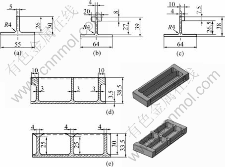
Fig.4 Dimensions of specimens: (a) I-section specimen; (b) T-section specimen; (c) J-section specimen; (d) Parallelly stiffened specimen; (e) Crossedly stiffened specimen (unit: mm)
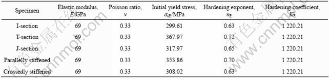
The material of the detailed model is 7B04-T7451 aluminium alloy, the properties of which listed in Table 1 were calculated with the uniaxial tensile test data. The yield and hardening parameters of the virtual material calculated with the method mentioned above are listed in Table 2, which are used to create the stress and strain data for FEM analysis.
Table 1 Material properties of aluminium alloy 7B04-T7451 (Detailed model)

Table 2 Virtual material properties (Equivalent model)
The simulations of the detailed models and the equivalent models were carried out using the commercial code ABAQUS. Press bend forming is a multi-step process, and the springback takes place continually. Both of the forming and springback processes were simulated with ABAQUS/Standard. The specimens were modelled with solid elements C3D8R. The number of the element layers along the thickness direction of the stiffener and the skin is four. The radii of the punch and the die corner are 35 mm, and the die gap is 165 mm. The thickness of the plastic equivalent plate is the same as the sum of the stiffener height and the skin thickness of the detailed model, and the width of the equivalent plate is the same as the skin width of the detailed model. Because the forming of the specimen is symmetric, half of the model was constructed. The assemblies of the detailed model and the equivalent model are shown in Fig.5 (by taking the I-section specimen as an example). Considering that the punch displacements of the practical manufacturing are around 5 mm, the range of the punch displacement in the FEM simulation is 3-7 mm.

Fig.5 Assemblies of I-section specimen: (a) Detailed model; (b) Equivalent model
4 Results and discussion
4.1 FEM simulation results and verification
FEM simulation results indicated that with the same punch displacement, the contours of the detailed model and the equivalent model after springback were very close. Taking the I-section specimen as an example, when the punch displacement is 5 mm, the final contours, the Mises stress distribution and the equivalent plastic strain distribution of the two models are shown in Fig.6, Fig.7, and Fig.8, respectively.

Fig.6 Vertical displacement graph of I-section specimen after springback: (a) Detailed model; (b) Equivalent model
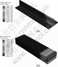
Fig.7 Mises stress distribution of I-section specimen after springback: (a) Detailed model; (b) Equivalent model

Fig.8 Equivalent plastic strain distribution of I-section specimen after springback: (a) Detailed model; (b) Equivalent model
The contrasts of the arc heights of different specimens after springback between the two models are shown in Fig.9. Arc height is defined as the distance from the lowest point of the outer surface of the specimen
to the horizontal surface of the die. The largest differences between the two models of different specimens formed with different punch displacements were as follows: I-section specimen 2.15%, T-section specimen 5.05%, J-section specimen 5.38%, parallelly stiffened specimen 5.44%, and crossedly stiffened specimen 4.56%. It can be noted that the equivalent model is accurate enough to be “equivalent”.
Fig.9 Arc heights of detailed model and equivalent model after springback: (a) I- section specimen; (b) T-section specimen; (c) J-section specimen; (d) Parallelly stiffened specimen; (e) Crossedly stiffened specimen

Compared with the detailed model, the efficiency of FEM simulation calculated with the equivalent model
has been improved by more than 80%. The contrast of the calculating time of the two models formed with different punch displacements is shown in Fig.10.

Fig.10 Contrast of FEM calculating time between detailed model and equivalent model
4.2 Error analysis
1) Because the height-to-thickness ratio of the stiffener of the detailed model is quite large, the stiffener buckles when the punch displacement is too large. In addition, small concave surface exists at the top of the stiffeners because of the punch force. Therefore, the actual punch displacement of the detailed model is smaller than the equivalent model, which causes smaller arc heights for the detailed model.
2) The virtual material parameters are calculated under the assumption that the neutral surface does not move during the bending and the springback.
3) The hardening parameters of the detailed model fitted with the uniaxial tensile test data may contain errors.
4) The equivalent model is established according to the wrap-around section, and the section that doesn’t wrap around the punch will magnify the arc height errors.
5 Conclusions
1) With the comprehensive analysis of the press bend forming and springback mechanics, a plastic equivalent plate made of a virtual material is constructed in order to solve the problem of press bend forming path optimization with FEM simulations.
2) Plenty of FEM simulation results indicate that the calculated errors of equivalent models are less than 6%, while the calculating efficiency is improved by more than 80%. The accuracy and efficiency of the proposed equivalent model make it convenient and indispensable in the future press bend forming path planning and process optimization.
3) By applying the method of plastic equivalent model to the large scale integrally stiffened panel with compound curvature contour, the optimization time of the press bend forming path with FEM analysis will be greatly reduced, and the virtual material properties can be calculated with the geometrical dimensions of the cross sections in the main bending direction.
4) This study also provides a good notion for the FEM simulations of other complicated forming process, and it is worth developing further.
References
[1] ZENG Yuan-song, HUANG Xia. Forming technologies of large integral panel [J]. Acta Aeronautica et Astronautica Sinica, 2008, 29(3): 721-727.
[2] MUNROE J, WILKINS K, AND GRUBER M. Integral airframe structures(IAS)―Validated feasibility study of integrally stiffened metallic fuselage panels for reducing manufacturing costs. NASA/CR-2000-209337 [R]. Seattle, Washington: Boeing Commercial Airplane Group, 2000.
[3] YANG He, GU Rui-jie, ZHAN Mei, LI Heng. Effect of frictions on cross section quality of thin-walled tube NC bending [J]. Trans Nonferrous Met Soc China, 2006, 16(4): 878-886.
[4] BAI Qian, YANG He, ZHAN Mei. Finite element modeling of power spinning of thin-walled shell with hoop inner rib [J]. Trans Nonferrous Met Soc China, 2008, 18(4): 6-13.
[5] HUBER M T. The elastic theroy of an orthotropic plate [M]. Macmillan: Timoshenko 60th Anniversary Volume, 1938: 89-92. (in German)
[6] HEARMON R F S, ADAMS E H. The bending and twisting of anisotropic plates [J]. British Journal Applied Physics, 1952, 3: 150-156.
[7] NARUOKA M, YONEZAWA H. A research on the application of the theory of orthotropic plates to steel highway bridges [C]// Internat Assoc for Bridge and Struct Engineering Fifth Congress. Lisbon: Preliminary Publication, 1956: 393-403.
[8] MORICE P B, LITTLE G. Load distribution on prestressed concrete bridge systems [J]. Structural Engineering, 1954, 32: 83-111.
[9] TROISTSKY M S. Stiffened plates bending, stability and vibrations [M]. Amsterdam: Elsevier Scientific Publishing Company, 1976: 62-113.
[10] BRADLEY K R. A sizing methodology for the conceptual design of blended-wing-body transports [D]. Washington: Joint Institute for Advancement of Flight Sciences, George Washington University, 2003.
[11] BRADLEY K R. A sizing methodology for the conceptual design of blended-wing-body transports. NASA/CR-2004-213016 [R]. Hampton, Virginia: Langley Research Center, 2004.
[12] MUKHOPADHYAY V. Blended-wing-body(BWB) fuselage structural design for weight reduction. AIAA 2005-2349 [R]. Hampton, VA: NASA Langley Research Center, 2005.
[13] ALLEN H G. Analysis and design of structural panels [M]. Oxford: Pergamon Press, 1969.
[14] SILVA M J, HAYES W C, GIBSON L J. The effect of non-periodic microstructure on the elastic properties of two-dimensional cellular solids [J]. International Journal of Mechanical Sciences, 1995, 37: 1161-1177.
[15] LIANG Sen, CHEN Hua-ling, CHEN Tian-ning, LIANG Tian-xi. Analytical study of the equivalent elastic parameters for a honeycomb core [J]. Journal of Aeronautical Materials, 2004, 24(3): 27-31.
[16] ZHAO Jin-sen. Research on equivalent models of the mechanical function for aluminum honeycomb sandwich panel [D]. Nanjing: University of Aeronautics and Astronautics, 2006: 34-50.
[17] PENG L X, LIEW K M, KITIPORNCHAI S. Analysis of stiffened corrugated plates based on the FSDT via the mesh-free method [J]. International Journal of Mechanical Sciences, 2007, 49: 364-378.
[18] MACHIMDAMRONG C, WATANABE E, UTSUNOMIYA T. Shear buckling of corrugated plates with edges elastically restrained against rotation [J]. International Journal of Structural Stability and Dynamics, 2004, 4(1): 89-104.
[19] XIA Li-juan, JIN Xian-ding, WANG Yang-bao. Equivalent analysis of honeycomb sandwich plates for satellite structure [J]. Journal of Shanghai Jiao Tong University, 2003, 37(7): 999-1001.
[20] XU Sheng-jin, KONG Xian-ren, WANG Ben-li, MA Xing-rui, ZHANG Xiao-chao. Method of equivalent analysis for statistics and dynamics behavior of orthotropic honeycomb sandwich plates [J]. 2000, 17(3): 92-95.
[21] de VIN L J. Curvature prediction in air bending of metal sheet [J]. Journal of Materials Processing Technology, 2000, 100: 257-261.
[22] de VIN L J. Expecting the unexpected, a must for accurate brake forming [J]. Journal of Matierials Processing Technology, 2001, 117: 244-248.
[23] WAGONER R H, LIB M. Simulation of springback: Through-thickness integration [J]. International Journal of Plasticity, 2007, 23: 345-360.
[24] HU Shi-guang, CHEN He-zheng. Principles of cold press forming of sheet metal [M]. Beijing: National Defence Industry Press, 1989: 45-62.
[25] HU Shi-guang, CHEN He-zheng. Engineering analysis of cold press forming of sheet metal [M]. Beijing: Beijing University of Aeronautics and Astronautics Press, 2004: 73-104.
Foundation item: Project(50675010) supported by the National Natural Science Foundation of China
Corresponding author: YAN Yu; Tel: +86-10-82338613; E-mail: anneyan@126.com
DOI: 10.1016/S1003-6326(08)60288-5
(Edited by YANG Bing)

