Petrel2ANSYS: Accessible software for simulation of crustal stress fields using constraints provided by multiple 3D models employing different types of grids
来源期刊:中南大学学报(英文版)2019年第9期
论文作者:潘懋 刘钰洋 刘诗琦
文章页码:2447 - 2463
Key words:numerical simulation of stress fields; corner-point grids; finite-element grids; Petrel; ANSYS
Abstract: Crustal stresses play an important role in both exploration and development in the oil and gas industry. However, it is difficult to simulate crustal stress distributions accurately, because of the incompatibilities that exist among different software. Here, a series of algorithms is developed and integrated in the Petrel2ANSYS to carry out two-way conversions between the 3D attribute models that employ corner-point grids used in Petrel and the 3D finite-element grids used in ANSYS. Furthermore, a modified method of simulating stress characteristics and analyzing stress fields using the finite-element method and multiple finely resolved 3D models is proposed. Compared to the traditional finite-element simulation-based approach, which involves describing the heterogeneous within a rock body or sedimentary facies in detail and simulating the stress distribution, the single grid cell-based approach focuses on a greater degree on combining the rock mechanics described by 3D corner-point grid models with the finely resolved material characteristics of 3D finite-element models. Different models that use structured and unstructured grids are verified in Petrel2ANSYS to assess the feasibility. In addition, with minor modifications, platforms based on the present algorithms can be extended to other models to convert corner-point grids to the finite-element grids constructed by other software.
Cite this article as: LIU Yu-yang, PAN Mao, LIU Shi-qi. Petrel2ANSYS: Accessible software for simulation of crustal stress fields using constraints provided by multiple 3D models employing different types of grids [J]. Journal of Central South University, 2019, 26(9): 2447-2463. DOI: https://doi.org/10.1007/s11771-019-4186-4.

J. Cent. South Univ. (2019) 26: 2447-2463
DOI: https://doi.org/10.1007/s11771-019-4186-4

LIU Yu-yang(刘钰洋)1, 2, PAN Mao(潘懋)1, 2, LIU Shi-qi(刘诗琦)1, 2
1. School of Earth and Space Science, Peking University, Beijing 100871, China;
2. The Key Laboratory of Orogenic Belts and Crustal Evolution (MOE), Peking University,Beijing 100871, China
 Central South University Press and Springer-Verlag GmbH Germany, part of Springer Nature 2019
Abstract: Crustal stresses play an important role in both exploration and development in the oil and gas industry. However, it is difficult to simulate crustal stress distributions accurately, because of the incompatibilities that exist among different software. Here, a series of algorithms is developed and integrated in the Petrel2ANSYS to carry out two-way conversions between the 3D attribute models that employ corner-point grids used in Petrel and the 3D finite-element grids used in ANSYS. Furthermore, a modified method of simulating stress characteristics and analyzing stress fields using the finite-element method and multiple finely resolved 3D models is proposed. Compared to the traditional finite-element simulation-based approach, which involves describing the heterogeneous within a rock body or sedimentary facies in detail and simulating the stress distribution, the single grid cell-based approach focuses on a greater degree on combining the rock mechanics described by 3D corner-point grid models with the finely resolved material characteristics of 3D finite-element models. Different models that use structured and unstructured grids are verified in Petrel2ANSYS to assess the feasibility. In addition, with minor modifications, platforms based on the present algorithms can be extended to other models to convert corner-point grids to the finite-element grids constructed by other software.
Key words: numerical simulation of stress fields; corner-point grids; finite-element grids; Petrel; ANSYS
Cite this article as: LIU Yu-yang, PAN Mao, LIU Shi-qi. Petrel2ANSYS: Accessible software for simulation of crustal stress fields using constraints provided by multiple 3D models employing different types of grids [J]. Journal of Central South University, 2019, 26(9): 2447-2463. DOI: https://doi.org/10.1007/s11771-019-4186-4.
1 Introduction
Crustal stresses are always related to natural stresses, including gravitational and tectonic stresses. During the long process of geological evolution, crustal stress fields continuously adjust and evolve due to various physical and chemical processes; thus, crustal stress distributions are complex in both time and space [1-8]. Stress fields are of great significance in exploration and development in the oil and gas field. Furthermore, the magnitudes and directions of crustal stress fields directly affect the formation and distribution of artificial fractures during hydraulic fracturing, which also plays a significant role in borehole stability during drilling [9-17].
Petrel is an integrated software package that was developed by SCHLUMBERGER [18], and permits oil and gas exploration and development using 3D geological models. It can establish complex 3D geological models and property models that are based on corner-point grids, and these models reflect the distribution and heterogeneous properties of reservoirs and formation rocks realistically and comprehensively [18-25]. Whereas, the corner-point grids based 3D geological models cannot directly simulate the stress fields using finite element analysis. The traditional approach is using interpolation algorithms to form the whole oilfield stress fields based on well logging data and seismic data. This method neglects the continuity and relationship between nearby cells. The simulation of stress fields in a 3D finite-element model can produce relatively accurate 3D stress models, which describes the magnitudes and directions of stress fields, through the adjustment of boundary loads and displacements [26-37]. In the meantime, the limited modeling ability is becoming one of the major problems in oilfield stress simulation. The finite-element-analysis software packages cannot set up elaborative 3D geological modeling, which reflects reservoir heterogeneity.
However, because of the different data organization schemes and incompatibilities among the data formats used in 3D geological models based on corner-point grids and 3D finite-element models based on finite-element grids, conversions among these models are incomplete. These incomplete conversions lead to defects in model transformations in the stress simulation procedure based on the finite-element method using geological models and attribute models, which primarily describe the constraints imposed by mechanical properties. Petrel2ANSYS has thus been developed to solve these problems.
A new method of simulating crustal stresses, based on the finite-element method and employing constraints from 3D geological models, and rock mechanical property models is developed in parallel with the development of the Petrel2ANSYS software platform. First, a complex geological model and a rock mechanical properties model, which are based on corner-point grids, are built using the Petrel software package. Second, the Petrel2ANSYS software platform is used to convert the model mentioned above to a 3D finite-element model based on a finite-element grid that is recognized by ANSYS. In addition, the numerical simulation of stresses is performed using ANSYS, which exports a 3D stress model based on a finite-element grid. Finally, the stress model based on a finite-element grid is converted to a 3D stress attribute model based on a corner-point grid using the Petrel2ANSYS software platform. The new model can then be visualized and subsequently analyzed using the Petrel software package.
2 Method
2.1 Petrel2ANSYS software platform
To overcome the difficulties in performing simulations that occurred due to the different data organization schemes used in different models, the Petrel2ANSYS software platform was developed to permit two-way conversion between different grid types to simplify the process of connecting 3D geological models and finite- element models. Thus, it carries out two-way conversions between different models. Simultaneously, the Petrel and ANSYS software packages are linked to the platform to simplify the simulation procedure.
The Petrel2ANSYS software platform integrates four modules. Specifically, the preprocessing module is used to modify the input corner-point grids; the transformation module converts corner-point grids to finite-element grids; the postprocessing module converts finite-element grids to corner-point grids; and the visualization module is used to visualize all of the models on different grids. The main procedure is shown in Figure 1. The 3D attribute model built by the Petrel software package flows into the preprocessing module of Petrel2ANSYS, where it is modified; the input file, which represents a corner-point grid, is converted into a finite-element grid in the transformation module. The output file then flows into ANSYS, which carries out a numerical simulation. After the simulation is finished, the stress model, which can be visualized in the visualization module, flows into the postprocessing module to be reconverted into a corner-point grid-based model. This model is then read and analyzed by the Petrel software package.
There are two basic data structures, the GNode and GCell, in Petrel2ANSYS software packages. The GNode is used to save every node’s information which mainly includes the node-number, the x-coordinate, y-coordinate and z-coordinate of corresponding node. The GCell data structure is designed for saving every cell’s information which includes the cell-number, the combination of the cell’s nodes and the cell-attribute, the parameters of rock mechanics, the validity of the current cell, etc. Meanwhile, several algorithms are designed and integrated to fulfill different functions (Figure 2).
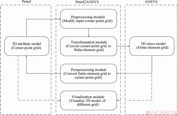
Figure 1 Major simulation workflow and module composition of Petrel2ANSYS software platform
In the preprocessing module, two algorithms are designed, the FileCheckProcess algorithm and the FileAnalysis algorithm. The FileCheckProcess algorithm is used to check file format, validity and integrity of the input corner-point grid file. The FileAnalysis algorithm is used to read the input file, extracting all nodes and cells information.
There are eight algorithms in transformation part: the FiniteNode algorithm, the FiniteCell algorithm, the FiniteCellMaterial algorithm, the FiniteCellAttribute algorithm, the FiniteModelLoad algorithm, the FiniteModelDisp algorithm, the StressSolution algorithm and OutputModelCtrl algorithm. The FiniteNode algorithm is designed for setting up the finite-element cells’ node model and all nodes are been saved using GNode. Nodes' information is extracted from the input files. Duplicated nodes are eliminated and the rest nodes are rearranged and sorted. The FiniteCell algorithm is used to rebuild the relationship between finite- element cells and nodes and the new nodes are linking to each finite-element cell, and the new relationships are saved using GCell. The FiniteCellMaterial algorithm is operated to appoint each cell a unique material number. The FiniteCellAttribute algorithm is used for linking the input corner-point grid cells’ attributes to the corresponding finite-element cell. The FiniteModelLoad algorithm and FiniteModelDisp algorithm are to set up the model load and displacement constraints. The StressSolution algorithm is designed for calling ANSYS to calculate stress distribution and the OutputModelCtrl algorithm is for modifying and saving the output model.
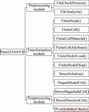
Figure 2 Algorithms composition of Petrel2ANSYS software
Three algorithms are designed and integrated in postprocessing module, the StressMagnitudeCtrl algorithm, the StressDirectionCtrl algorithm and PostValidityCheck algorithm. The StressMagnitudeCtrl algorithm and StressDirectionCtrl algorithm are to link, and add the magnitude and direction of finite-element cells’ stress attributes to the corresponding corner-point cells. The PostValidityCheck algorithm is used to check the validity of new corner-point grid model. And the whole software is developed by C# and C++.
The visualization module, developed based on OpenSceneGraph, is used to visualize the models with 3D visualization operations. OpenSceneGraph is an open source, cross-platform graphics development kit designed for visualization of scientific computing and high-performance graphics applications, such as aircraft simulation, games, and virtual reality. Based on the concept of scene graph, it provides an object-oriented framework on OpenGL, which makes developers free from the call to implement and optimize the underlying graphics, and it provides many additional practical tools for the rapid development of graphics applications.
2.2 Building geological models in Petrel
Petrel is an integrated software package that is widely used in the oil and gas field. Using Petrel, researchers can observe and describe reservoirs in 3D space from multiple angles, thus deepening their understanding of geological characteristics and the distribution of reservoir parameters. Moreover, Petrel provides a foundation for the integration of geology, geophysics and reservoir engineering, and thus helps establish a basis for detailed exploration and the setup and adjustment of development plans. The software, which enables integrated seismic interpretation, structural modeling, facies modeling, reservoir property modeling, reservoir simulation, visualization and virtual reality display, provides an information-sharing platform for geologists, geophysicists, rock physicists and reservoir engineers. Moreover, the software integrates a variety of advanced technologies, specifically powerful modeling techniques, high-precision 3D gridding techniques, deterministic and stochastic modeling of sedimentary facies, rock physics modeling techniques, advanced 3D visualization and virtual reality techniques [18, 38].
Finely resolved 3D geological and attribute models can be established using Petrel. The main modeling procedure of the software applied in this work is shown in Figure 3. To begin, some basic data, including seismic data, well head data, well path data, and well tops, are used to build a 3D geological model. Moreover, based on the geological model and well logs, a 3D facies model is established using interpolation algorithms. A 3D attribute model or a rock mechanics model that represents the 3D elastic modulus model, the 3D Poisson ratio model and 3D density model is then established based on constraints provided by the 3D geological and facies models, together with the well logs and experimental data using interpolation algorithms, such as sequence Gaussian simulation. The detailed modeling process can be accessed in Refs. [18, 38].
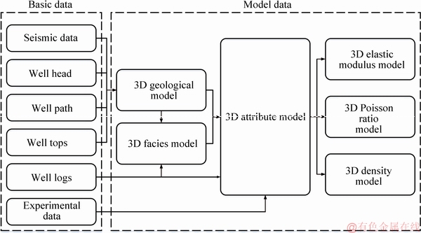
Figure 3 Procedure used to establish a corner-point grid model using Petrel software package
2.3 Transformation between different grid types using Petrel2ANSYS
The Petrel2ANSYS software platform was developed to effectively transform 3D geological and attribute models based on corner-point grids into 3D finite-element models based on finite- element grids. Although Petrel can derive many different types of grids, including corner-point grids, it cannot directly export finite-element grids. The ECLIPSE keywords format, which is based on the corner-point grid system, is thus selected to promote the continuity of the subsequent simulation procedure. In addition, considering the compatibility issues that arise between different software packages during the simulation procedure, the stress model, which is based on the finite- element grids employed by ANSYS, is converted to the corresponding model in the ECLIPSE keywords format for subsequent analysis.
A series of files exported by the Petrel software package is modified by the preprocessing module of the Petrel2ANSYS software platform. Based on the modified files, the transformation module of the Petrel2ANSYS software platform is applied to generating the basic structure files of a finite-element grid, which in detail are the ASFEFG files, defined by the author research group in parallel with recognition by ANSYS. ANSYS can read these files in order to build exactly corresponding 3D geological and attribute models on finite-element grids for simulations of stresses. The main transformation procedure and some file examples are shown in Figure 4.
2.4 Stress simulation procedure using ANSYS
ANSYS offers a comprehensive software suite that spans the entire range of physics, providing access to virtually any field of engineering simulation that a design process requires [26]. ANSYS, developed by ANSYS Corporation, is a large general finite-element analysis software package that can perform structural, fluid dynamics, electric field, magnetic field and sound field analyses. It is widely used in nuclear industry, railway engineering, petrochemistry, aerospace engineering, manufacturing of machinery, resource engineering, transportation engineering, military applications and defense industry, electronics, civil engineering, shipbuilding, medicine, light industry, mining, water conservation, design of household appliances, and many other fields. It represents a flexible means of performing numerical simulations of stress fields using the finite-element method. Tectonics are considered in such calculations with high accuracy and flexibility, and the calculation point can be specified arbitrarily. This approach is suitable for projects or engineering applications with a certain amount of geological data and high-precision requirements.
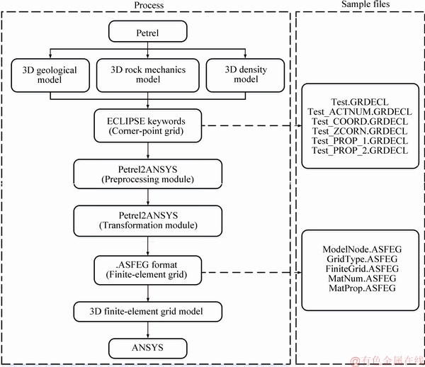
Figure 4 Workflow used to transform 3D corner-point grid models in Petrel and 3D finite-element grid models in ANSYS and sample files
The traditional solution used in the simulation of stress fields based on the finite-element method often uses inside modeling module to set up the reservoir model. Due to the limited modeling ability, the model cannot fully represent the structure and morphology of underground space. In addition, it always assigns the same rock mechanical properties, such as elastic modulus and the Poisson ratio, to certain rock types or facies. This method ignores anisotropy within rock types or facies. In this study, a new approach was proposed in the face of this shortcoming in order to improve the accuracy with which anisotropic properties are described within certain rock types or facies. High-precision 3D rock mechanics attribute models that are based on the constraints imposed by 3D geological models and facies models can be obtained using professional- grade geological modeling software (e.g. Petrel) to fully describe the anisotropic properties of certain rock types and facies. Simultaneously, in order to fully respect the anisotropic characteristics of rock types and facies, each single grid cell is assigned certain material properties related to the rock mechanics models during the transformation procedure. As a result, the anisotropy of rock mechanical properties is accurately represented, thus improving the accuracy of stress simulations. The entire procedure is shown in Figure 5.
To establish the 3D stress model, a node model must first be established. The grid type is then defined to establish the finite-element grid model. Afterwards, the material number and properties are assigned to each grid cell to link them to the 3D attribute models (rock mechanics models). A simulation is then performed to obtain the 3D stress model with load and displacement constraints. The model output is obtained by following this procedure. The simulation procedure using ANSYS and the input files are listed in Figure 6. Specifically, to simplify the procedure and enhance its consistency, all of the input files can be generated by the transformation module of Petrel2ANSYS with the corresponding load and displacement constraints as inputs.
2.5 Postprocessing of 3D stress models using Petrel2ANSYS
The basic finite-element model is built using Petrel2ANSYS, and the simulation is then performed. The load and displacement constraints are applied using ANSYS to obtain the 3D stress model. The 3D stress model based on a finite- element grid provided by ANSYS includes six main parts, specifically the magnitudes and directions of the stress components in the x-, y- and z-direction and the minimum, maximum and intermediate principal stresses. To perform the subsequent analyses, re-conversion into the corner-point grid type that can be read in Petrel is required, and the postprocessing module is designed to carry out this function. The 3D stress model based on a finite-element grid is then transformed into a corner-point grid, and the stress attributes are added to the ECLIPSE keyword files. The main procedure and some sample files are shown in Figure 7.
3 Grid transformation
Grid-based data organization scheme is the basis of the grid transformation algorithm, and the two-way conversion algorithm is a core element of the transformation module and the postprocessing module in carrying out the stress simulation procedure. Grid-based data organization schemes, specifically corner-point grids and finite-element grids, are analyzed, and several sample models are tested to demonstrate the validity of the algorithm. Furthermore, real oilfield data are then employed to fully assess the transformation algorithms implemented in the Petrel2ANSYS software platform.
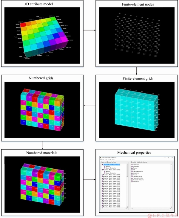
Figure 5 Procedure used to number materials and define properties of each grid cell
3.1 Analysis of gridded data organization schemes
Corner-point grids are structured grids and represent one of the most suitable types of grids for geological modeling and reservoir simulation in oil and gas fields. These grids were introduced by Ponting and have the advantages of flexibility and variable lengths of different grid cells. Corner-point grids can describe depth variations, fluid distributions and fluid mechanics in porous media with high-precision and accuracy [39, 40].
From the perspective of model construction, corner-point grids are similar to general hexahedral grids, and they may be either structured or unstructured. For a structured grid with a size of Nx×Ny×Nz, the corner point that is used to generate the volume cell structure is defined by two control surfaces with (Nx+1)×(Ny+1) regular topological structures, and sliding intermediate lines define the top and bottom boundaries of each element. There are initially Nx+1 lines along the x-axis, Ny+1 lines along the y-axis and Nz+1 lines along the z-axis. All of the lines separate the space into Nx, Ny and Nz units; as a result, the space is divided into Nx×Ny×Nz grid cells. Each grid cell is an irregular hexahedron, and the coordinates of the eight nodes are defined by the top and bottom control surfaces and the z values via linear interpolation. In particular, adjacent grid cells do not share the same point along the interface at the joint between two grid cells; for each grid cell, the joint point is written for each grid. Thus, duplicate points exist in corner-point grid files.
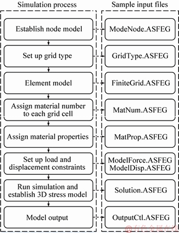
Figure 6 Procedure used to simulate stresses using ANSYS and input sample files generated using Petrel2ANSYS software platform
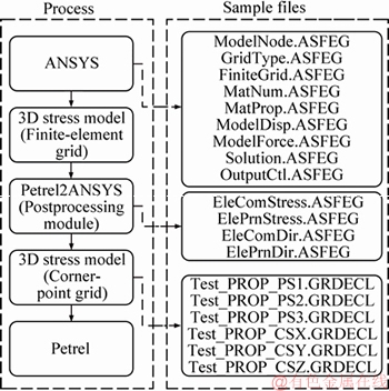
Figure 7 Postprocessing module of Petrel2ANSYS
Considering unstructured grids, a limited approach is applied in detail. A label is applied to each grid cell to describe whether it is active or inactive, using the same construction method as the structured grid database. Figure 8 shows a sample unstructured corner-point grid, which is stored as a formal structured grid with full information. The upper panels in Figure 8 show an overhead view of the grid, whereas the lower panels show a 3D view of the grid; cyan grid cells are active, whereas blue grid cells are inactive.
Nodes are the basic elements that make up finite-element grids. Considering each grid element, there are eight points. This feature contrasts with corner-point grids, in which the neighboring grid cells share the same nodes to organize the grid. Moreover, neighboring grid cells, which share an interface, have the same number of degrees of freedom. Therefore, to convert a corner-point grid with a structured database, points are selected and sorted in a certain sequence to coordinate with the corresponding grid cells, and the grid cells are then formed using specifically selected nodes. Simultaneously, for the unstructured corner-point grid, all of the point information is transformed into the corresponding node. However, considering the requirements of finite-element analysis, only the active grid cells can be allowed to form the corresponding grid. Thus, the inactive grid cells are neglected in carrying out the full conversion function, as shown in Figure 9. Cyan grid cells are active, whereas blue grid cells are inactive in the corner-point grid; red grid cells are related to the finite-element grid, and node numbers are shown in white.
3.2 Transformation from corner-point grids to finite-element grids
For a simplified corner-point grid cell system, as shown in Figure 10(a), there are two independent cells (Cell I and Cell II) and 16 nodes (Nodes 1-12,2′, 5′, 8′, 11′). Nodes 1, 2, 4, 5, 7, 8, 10, 11 belong to Cell I and Nodes 2′, 3, 5′, 6, 8′, 9, 11′, 12 compose Cell II. Compared with the same cell system based on finite-element grid, as shown in Figure 10(b), there are two independent cells (Cell I and Cell II) and only 12 nodes (Nodes 1-12). For the undeformed grid cells, because of the neighboring grid cells share the nodes to organize the cells, the duplicated nodes (Nodes 2′, 5′, 8′, 11′) are eliminated when the corner-point grid is transformed to finite-element grid. Considering the deformed grid cells, as shown in Figures 10(c) and (d), there are two independent cells (Cell I and Cell II) and 16 nodes (Nodes 1-12, 2′, 5′, 8′, 11′). The neighboring grid cells do not share the nodes to organize the cells; thus, the nodes are not eliminated when the transforming is operated. Simultaneously, for the unstructured corner-point grid cells, as shown in Figure 10(e), there are two independent cells: Cell I (Nodes 1, 4, 7, 10, 2′, 5′, 8′, 11′) is inactive and Cell II (Nodes 2, 3, 5, 6, 8, 9, 11, 12) is active. During the transformation process, all corner-point grid cells’ nodes are operated to transform into finite-element grid cells’ nodes (Nodes 1-12). While, for the active cells, the nodes (Nodes 2, 3, 5, 6, 8, 9, 11, 12) are organized, and the inactive cells’ nodes (Nodes 1, 2, 4, 5, 7, 8, 10, 11) are on the contrary, as shown in Figure 10(f). As a result, the new cell system is organized.
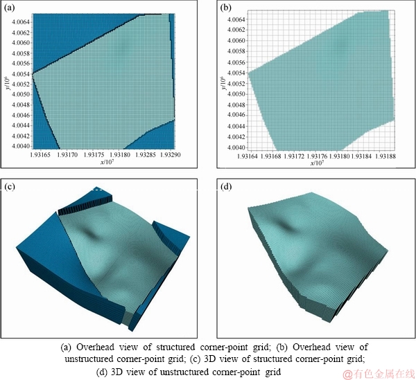
Figure 8 Structured and unstructured corner-point grid with and without inactive grid cells (Cyan grid cells are active, whereas blue grid cells are inactive):
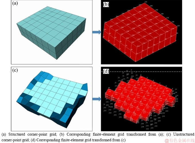
Figure 9 Samples of grid transformation from structured and unstructured corner-point grids to finite-element grid:
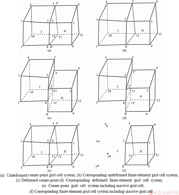
Figure 10 Transformation theory between corner-point grid cell and finite-element grid cell:
Actual oilfield data are employed to assess the grid transformation module implemented in the Petrel2ANSYS software platform, which can handle both structured and unstructured corner- point grids, regardless of whether they include attribute information. The geological models based on corner-point grids are built using the Petrel software package. These models include a structured grid with a grid size of 168990 (which includes both grid cells with and without heterogeneous properties) and an unstructured grid with a grid size of 180780, of which 130780 cells are active. These grids are successfully converted into finite-element grids. In addition, the model can be meaningfully recognized using ANSYS.
Figure 11 shows the examples of grid transformation from a structured corner-point grid to a finite-element grid with a grid size of 168990. The grids in Figures 11(a) and (b) do not include any heterogeneous attributes, while the grids in Figures 11(c) and (d) include heterogeneous attributes, namely the cell volume.
Figure 12 shows the examples of grid transformation from an unstructured corner-point grid to a finite-element grid with a grid size of 180780, of which 130780 cells are active.Figures 12(a) and (b) show the overhead view of the models and Figures 12(c) and (d) show the 3D view of the models.
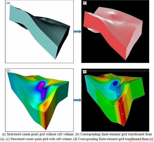
Figure 11 Examples of transformation from a structured corner-point grid to a finite-element grid without and with cell volume:
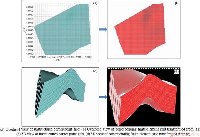
Figure 12 Examples of transformation from an unstructured corner-point grid to a finite-element grid:
3.3 Transformation from a finite-element grid to a corner-point grid
The finite-element grid system is the basic grid system employed to save stress simulation results. All stress information is saved in finite-element grid cells. For a simplified finite-element grid cell system, as shown in Figure 10(b), there are two independent cells (Cell I and Cell II) and 12 nodes (Nodes 1-12). Nodes 1, 2, 4, 5, 7, 8, 10, 11 belong to Cell I and Nodes 2, 3, 5, 6, 8, 9, 11, 12 belong to Cell II. Considering the corner-point gird cells, the neighboring cells do not share the nodes to organize the cells. The sharing nodes need to be rebuilt and organized the new grid system. When the cells are transformed, the sharing nodes (Nodes 2, 5, 8, 11) are copied and nodes (Nodes 2′, 5′, 8′, 11′) are generated. As a result, Nodes 1-8 belong to Cell I and Nodes 2′, 3, 5′, 6, 8′, 9, 11′, 12 compose Cell II. What’s more, there are two independent cells (Cell I and Cell II) and 16 nodes (Nodes 1-12, 2′, 5′, 8′,11′) in the corner-point grid system, as show in
Figure 10(a), compared to finite-element grid system. For the deformed cells of corner-point grid and finite-element grid, as shown in Figures 10(c) and (d), there are 2 cells (Cell I and Cell II) and 16 nodes (Nodes 1-12, 2′, 5′, 8′, 11′). During the transformation process, the nodes remain unchanged because the neighboring cells do not share the same nodes. Considering the active and inactive cells of corner-point grid and finite-element gird, the transformation process is the same as that of the undeformed cells of corner-point grid and finite-element gird. Meanwhile, the cell attribute is assigned to the corresponding new cell in all situation of transformation process.
Sample data with a grid size of 168990 are imported for validation of transformation from finite-element grid to corner-point grid, as shown in Figure 13. For a transformed grid, stress characteristics are simulated by applying the correct load and displacement in ANSYS to obtain a 3D stress characteristics model that is based on a finite- element grid, as shown in Figure 13(a). The postprocessing module of Petrel2ANSYS is employed to reconvert the model from a finite- element grid into a corner-point grid (Figure 13(b)).
4 Test with real data
Real data from the XX oilfield, which is located in Yan’an County of Shanxi Province, north-central China, are used to assess the validity of the stress simulation procedure. The area is a typical tight oil reservoir including 37 wells. The porosity of this area ranges from 0.3% to 11.87%, with 3.78% in average. The area’s permeability varies from 0.1 to 27.54 mD and the average permeability is about 11.37 mD. 3D models of elastic modulus, the Poisson ratio and density based on constraints imposed by geological and facies models described in Refs. [41, 42] are imported into the Petrel2ANSYS software platform, which is used to transform the corner-point grid models into finite-element grid-based models. It consists of 1351920 grids and 2704920 nodes with 9 different attributes, including porosity, permeability, oil saturation, cell volume, elastic modulus, the Poisson ratio of nodes and density etc. Considering the finite-element grid, 1351920 cells with different rock mechanic attributes make up this model, while the number of nodes is 1430457.
Furthermore, load and displacement constraints are established based on these studies. A top load of 31.2 MPa and side surface loads of 2.4 MPa and 6 MPa are imposed, and displacement constraints are applied to all of the surfaces. Thus, a 3D stress model is constructed.
Compared with the actual measured values reported by the previous studies from 4 different wells [41, 42], the values produced by the simulation for the grid cells corresponding to individual wells agree well with the actual measurements for those wells within ±5% as listed in Table 1.
As shown in Figure 14, the first line is 3D attribute models based on corner-point grids of elastic modulus, Poisson ratio and density, which are the original input models. The second line of Figure 14 shows 3D stress models based on finite- element grid including the maximum and minimum horizontal stress which are the simulation results after grid transformation and finite-element analysis based on the input models. The third line in Figure 14 shows 3D stress models based on corner-point grid including the maximum and minimum horizontal stress and the fourth line shows 3D stress models based on corner-point grid of horizontal stress deviation, which shows the results after postprocessing module.
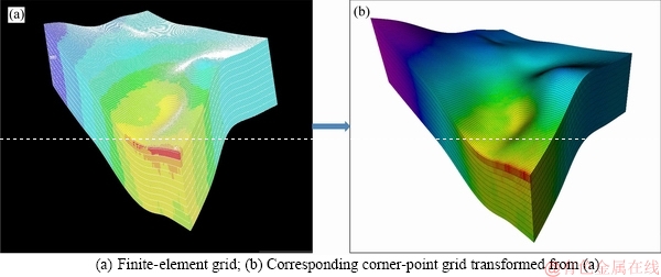
Figure 13 Transformation from a finite-element grid to a corner-point grid with maximum principle stress:
Table 1 Comparison of results between real estimation results and simulation results
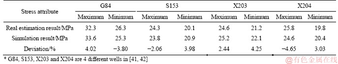
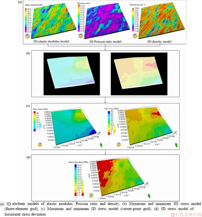
Figure 14 Procedure test using data from XX oilfield and corresponding stress simulation result models:
5 Discussion
Some basic data are needed to obtain high-precision geological and facies models. However, the accuracy and sources of data are often questionable. In addition, interpolation algorithms are required to construct attribute models, and the selected algorithm and parameter values directly affect the accuracy of the models and consequently influence the resulting stress simulations.
Load and displacement constraints are required in numerical simulation of stress attributes using finite-element analysis, and the setting of these constraints can directly affect the simulation results. Simultaneously, boundary constraints and loads are difficult to obtain directly. Thus, an alternative method is recommended, in which the target region is combined with a large-scale field for which the load and displacement constraints can easily be obtained. However, this approach also displays some shortcomings, such as the accuracy of the material properties outside the target region and the grid resolution of the combined region.
The development of the Petrel2ANSYS software platform effectively solves the problems associated with two-way conversion between corner-point grids and finite-element grids. Although the algorithms that make up the software platform were originally designed for using with Petrel and ANSYS, they can be extended for other software packages with slight modifications.
Although geological models that include faults are not discussed in this work, the software platform can solve problems with deformed grids, which assign faults to two-dimensional planes to deliver the tensional stresses. Moreover, some modifications are still needed to determine whether stresses can pass through faults, depending on their scales.
6 Conclusions
1) The Petrel2ANSYS software platform described in this paper represents a new approach in the simulation of stresses based on finite-element analysis. It enables the incorporation of the geological models produced by geological modeling software, and the linkages to finite- element grids produced by finite-element analysis software using different grid organization schemes. Some test samples and real oilfield models are examined using the software platform, which has been successfully operated.
2) A modification to the procedure used to perform numerical simulations of stresses is described here. In detail, this modification involves assigning densities and rock mechanical properties to single grid cells. Thus, Petrel2ANSYS enables complete descriptions of the isotropic properties within reservoir rocks or facies, and avoids the neglect of anisotropic properties within geological bodies, thus effectively linking rock mechanics models to finite-element-based material properties.
3) The 3D stress models based on finite- element grids produced by finite-element analysis software can be extended and reconverted into corner-point grids. Such grids are recognized by geological software and can be used in subsequent analyses and numerical simulations of reservoirs performed using other software packages, such as fracture simulations based on these stress fields.
Acknowledgment
We express our sincere gratitude to ZHU Dan-ni, LIANG Yao-huan, ZHANG Chi and CAO Kai, who provided substantial help in carrying out this work. We also thank HUANG Sheng-xuan, YU Stella and Springer Nature Author Services, who provided linguistic assistance.
References
[1] HAYASHI M, KANAGAWA T, HIBINO S, MOTOZIMA M, KITAHARA Y. Detection of anisotropic geo-stresses trying by acoustic emission, and non-linear rock mechanics on large excavating caverns [C]// Proceedings of the 4th ISRM Congress. Montreux, Switzerland: International Society for Rock Mechanics and Rock Engineering. 1979: 211-218.
[2] TEUFEL L. In situ stress and natural fracture distribution at depth in the Piceance Basin, Colorado: implications to stimulation and production of low permeability gas reservoirs [C]// Proceedings of the 27th U.S. Symposium on Rock Mechanics (USRMS). Tuscaloosa, Alabama, USA: American Rock Mechanics Association, 1986: 377-392.
[3] WANG Hong-cai, WANG Wei, WANG Lian-jie, SUN Bao-shan, XIA Bo-ru. Three dimensional tectonic stress field and migration of oil and gas in Tanhai [J]. Acta Geosicientia Sinica, 2002, 23(2): 175-178.
[4] MA Shu-zhi, JIA Hong-biao, YI Shun-min, GONG Shu-yun. Analysis of geostress field simulation in Luohu fault zone with 3D finite element method [J]. Chinese Journal of Rock Mechanics and Engineering, 2006, 25(z2): 3898-3903. DOI: 10.3321/j.issn:1000-6915.2006.z2.088. (in Chinese)
[5] ZANG A, STEPHANSSON O. Stress field of the earth’s crust [M]. Dordrecht: Springer Netherlands, 2010. DOI: 10.1007/978-1-4020-8444-7.
[6] SHI Xian, CHENG Yuan-fang, CAI Jun, SUN Yuan-wei, YUAN Zheng. Parametric analysis in the horizontal stress calculation based on numerical inversion method [J]. Electronic Journal of Geotechnical Engineering, 2013, 18(1): 5673-5684. http://www.ejge.com/2013/Abs2013.486.htm.
[7] ZHAO Tong-bin, ZHANG Ming-lu, LI Zhan-hai, ZHANG Ze. Numerical simulation of stress relieving and analysis of influencing factors on geostress measurement [C]// Proceedings of the Taishan Academic Forum―Project on Mine Disaster Prevention and Control. Qingdao, China: Atlantis Press, 2014: 1-9. DOI: 10.2991/mining-14.2014.37.
[8] YOSHIDA M. Re-evaluation of the regional tectonic stress fields and faulting regimes in central Kyushu, Japan, behind the 2016 Mw 7.0 Kumamoto Earthquake [J]. Tectonophysics, 2017, 712-713(1): 95-100. DOI: 10.1016/j.tecto.2017. 05.011.
[9] ZANG A, STEPHANSSON O, ZIMMERMANN G. Keynote: fatigue hydraulic fracturing [J]. Procedia Engineering, 2017, 191(1): 1126-1134. DOI: 10.1016/j.proeng.2017. 05.287.
[10] YOON J S, ZIMMERMANN G, ZANG A. Discrete element modeling of cyclic rate fluid injection at multiple locations in naturally fractured reservoirs [J]. International Journal of Rock Mechanics and Mining Sciences, 2015, 74(1): 15-23. DOI: 10.1016/j.ijrmms.2014.12.003.
[11] MAGNIER A, SCHOLTES B, NIENDORF T. Analysis of residual stress profiles in plastic materials using the hole drilling method―Influence factors and practical aspects [J]. Polymer Testing, 2017, 59(1): 29-37. DOI: 10.1016/ j.polymertesting.2016.12.025.
[12] HUANG Sai-peng, LIU Da-meng, YAO Yan-bin, GAN Quan, CAI Yi-dong, XU Lu-lu. Natural fractures initiation and fracture type prediction in coal reservoir under different in-situ stresses during hydraulic fracturing [J]. Journal of Natural Gas Science and Engineering, 2017, 43(1): 69-80. DOI: 10.1016/j.jngse.2017.03.022/.
[13] PARVIZI H, REZAEI-GOMARI S, NABHANI F, TURNER A. Evaluation of heterogeneity impact on hydraulic fracturing performance [J]. Journal of Petroleum Science and Engineering, 2017, 154(1): 344-353. DOI: 10.1016/j.petrol. 2017.05.001.
[14] ADACHI J, SIEBRITS E, PEIRCE A, DESROCHES J. Computer simulation of hydraulic fractures [J]. International Journal of Rock Mechanics and Mining Sciences, 2007, 44(5): 739-757. DOI: 10.1016/j.ijrmms.2006.11.006.
[15] HILL R E, PETERSON R E, WARPINSKI N R, TEUFEL L W, ASLAKSON J K. Techniques for determining subsurface stress direction and assessing hydraulic fracture azimuth [C]// Proceedings of SPE Eastern Regional Meeting. Charleston, West Virginia, USA: Society of Petroleum Engineers. 1994: 305-320. DOI: 10.2118/29192-MS.
[16] MILLER II W K, PETERSON R E, STEVENS J E, LACKEY C B, HARRISON C W. In-situ stress profiling and prediction of hydraulic fracture azimuth for the West Texas Canyon sands formation [J]. SPE Production & Facilities, 1994, 9(3): 204-210. DOI: 10.2118/21848-PA.
[17] MCLELLAN P. In-situ stress prediction and measurement by hydraulic fracturing, Wapiti, Alberta [J]. Journal of Canadian Petroleum Technology, 1988, 27(2): 85-95. DOI: 10.2118/87-38-58.
[18] SCHLUMBERGER. Petrel 2016 Introduction [EB/OL]. [2018-04-08].https://www.software.slb.com/products/petrel/petrel-2016,2016-08-07/.
[19] WU Qiang, XU Hua. Three-dimensional geological modeling and its application in Digital Mine [J]. Science China: Earth Sciences, 2014, 57(3): 491-502. DOI: 10.1007/s11430-013-4671-9.
[20] NGUYEN B N, HOU Z, BACON D H, MURRAY C J, WHITE M D. Three-dimensional modeling of the reactive transport of CO2 and its impact on geomechanical properties of reservoir rocks and seals [J]. International Journal of Greenhouse Gas Control, 2016, 46(1): 100-115. DOI: 10.1016/j.ijggc.2016.01.004.
[21] DENNEY D. Seismically integrated geological modeling [J]. Journal of Petroleum Technology, 1998, 50(1): 46-47. DOI: 10.2118/0198-0046-JPT.
[22] HOFFMAN D R. Petrel workflow for adjusting geomodel properties for simulation [C]// Proceedings of the SPE Middle East Oil and Gas Show and Conference. Manama, Bahrain: Society of Petroleum Engineers. 2013: 1-16. DOI: 10.2118/164420-MS.
[23] PULITI A, ERBA M, FRANCESCONI A, EI-AGELI L. Geological modelling of a structurally complex reservoir [C]// Proceedings of the International Meeting on Petroleum Engineering. Beijing, China: Society of Petroleum Engineers. 1995: 129-140. DOI: 10.2118/29962-MS.
[24] SEN G. Sequence stratigraphic modeling using outcrop data in 3D space [C]// Proceedings of the SPE Middle East Oil and Gas Show and Conference. Manama, Bahrain: Society of Petroleum Engineers. 2013: 1-4. DOI: 10.2118/164396-MS.
[25] WU R, TURPIN A, MACDONALD D, KAVANAGH D. A procedure for the configuration of an inflow control device completion using reservoir modelling and simulation in the North Amethyst Pool [C]// Proceedings of the SPE Reservoir Characterisation and Simulation Conference and Exhibition. Abu Dhabi, UAE: Society of Petroleum Engineers, 2011: 1-13. DOI: 10.2118/147960-MS.
[26] ANSYS. ANSYS 18.0 [EB/OL]. [2017-12-08]. http://www.ansys.com/,2017-01-31/.
[27] LIN Tie-jun, YU Hao, LIAN Zhang-hua, YI Yong-gang, ZHANG Qiang. Numerical simulation of the influence of stimulated reservoir volume on in-situ stress field [J]. Journal of Natural Gas Science and Engineering, 2016, 36(1): 1228-1238. DOI: 10.1016/j.jngse.2016.03.040.
[28] YIN Shuai, DING Wen-long, ZHOU Wen, SHAN Yu-ming, XIE Run-cheng, GUO Chun-hua, CAO Xiang-yu, WANG Ru-yue, WANG Xing-hua. In situ stress field evaluation of deep marine tight sandstone oil reservoir: A case study of Silurian strata in northern Tazhong area, Tarim Basin, NW China [J]. Marine and Petroleum Geology, 2017, 80(1): 49-69. DOI: 10.1016/j.marpetgeo.2016.11.021.
[29] LI Feng. Numerical simulation of 3D in-situ stress in Hailaer oil field [J]. Procedia Environmental Sciences, 2012, 12(1): 273-279. DOI: 10.1016/j.proenv.2012.01.277.
[30] LAVROV A, LARSEN I, HOLT R M, HOLT R M, BAUER A, PRADHAN S. Hybrid FEM/DEM simulation of hydraulic fracturing in naturally-fractured reservoirs [C]// Proceedings of the 48th US Rock Mechanics/Geomechanics Symposium. Minneapolis, Minnesota, USA: American Rock Mechanics Association, 2014: 1-8. https://www.onepetro.org/conferen ce-paper/ARMA-2014-7107.
[31] SITHARAM T G, KUMARI S D A. Numerical simulations of tunnels using DEM and FEM [C]// Proceedings of the 13th ISRM International Congress of Rock Mechanics. Montreal, Canada: International Society for Rock Mechanics, 2015: 1-7. https://www.onepetro.org/conference-paper/ISR M-13CONGRESS-2015-388.
[32] YANG Y S, LEE J O, KIM B J. Structural reliability analysis using commercial FEM package [C]// Proceedings of the the 6th International Offshore and Polar Engineering Conference. Los Angeles, California, USA: International Society of Offshore and Polar Engineers, 1996: 387-394. https:// www.onepetro.org/conference-paper/ISOPE-I-96-307.
[33] ZHANG Kun-yong, SHI Jian-yong, YIN Zong-ze. Stability analysis of channel slope based on FEM strength reduction [C]// Proceedings of the 20th International Offshore and Polar Engineering Conference. Beijing, China: International Society of Offshore and Polar Engineers, 2010: 757-762. https://www.onepetro.org/conference-paper/ISOPE-I-10-600.
[34] TIAN Yi-ping, LIU Xiong, LI Xing. 3-D numerical finite element method of tectonic stress field simulation based on irregular corner-point grid [C]// Proceedings of the International Symposium on Intelligence Computation and Applications. Heidelberg, Berlin: Springer, 2010: 146-153. DOI: 10.1007/978-3-642-16388-3_16.
[35] ZIENKIEWICZ O C. Stress analysis of rock as a ‘No Tension’ material [J]. Géotechnique, 1968, 18(1): 56-66. DOI: 10.1680/geot.1968.18.1.56.
[36] LIU Jing-shou, DING Wen-long, YANG Hai-ming, WANG Ru-yue, YIN Shuai, LI Ang, FU Fu-quan. 3D geomechanical modeling and numerical simulation of in-situ stress fields in shale reservoirs: A case study of the lower Cambrian Niutitang formation in the Cen'gong block, South China [J]. Tectonophysics, 2017, 712-713(1): 663-683. DOI: 10.1016/ j.tecto.2017.06.030.
[37] JU Wei, SHEN Jian, QIN Yong, MENG Shang-zhi, WU Cai-fang, SHEN Yu-lin, YANG Zhao-biao, LI Guo-zhang, LI Chao. In-situ stress state in the Linxing region, eastern Ordos Basin, China: Implications for unconventional gas exploration and production [J]. Marine and Petroleum Geology, 2017, 86(1): 66-78. DOI: 10.1016/j.marpetgeo. 2017.05.026.
[38] SCHLUMBERGER. ECLIPSE 2014 [EB/OL]. [2018-04-08]. https://www.software.slb.com/products/eclipse/eclipse-2014, 2014-06-08.
[39] PONITING D K. Corner point grid geometry in reservoir simulation [C]// Proceedings of the 1st European Conference on the Mathematics of Oil Recovery. Cambridge, UK: European Association of Geoscientists & Engineers, 1989: 1-4. DOI: 10.3997/2214-4609.201411305.
[40] PARK C H, SHINN Y J, PARK Y C, HUH D G, LEE S K. PET2OGS: Algorithms to link the static model of Petrel with the dynamic model of OpenGeoSys [J]. Computers & Geosciences, 2014, 62(1): 95-102. DOI: 10.1016/j.cageo. 2013.09.014.
[41] ZHANG Zhi-qiang, SHI Yong-min, BU Xiang-qian, LIANG Yao-huan, ZHANG En-yu. A study of in-situ stress direction change during waterflooding in the low permeability reservoirs [J]. Acta Scientiarum Naturalium Universitatis Pekinensis, 2016, 52(5): 861-870. DOI: 10.13209/j.0479- 8023.2015.140. (in Chinese)
[42] ZHU Dan-ni, PAN Mao, DANG Yong-chao, ZHU Zhi-ping, LIU Pei-gang, SHI Yong-min. Characterization and fracturing stimulation on single sand body of tight sandstone oil reservoir in Ansai Oilfield [J]. Acta Scientiarum Naturalium Universitatis Pekinensis, 2016, 52(3): 457-466. DOI: 10.13209/j.0479-8023.2015.117.(in Chinese)
(Edited by ZHENG Yu-tong)
中文导读
Petrel2ANSYS:基于不同网格模型的地应力场有限元数值模拟辅助软件系统
摘要:地应力是岩体在自然状态下存在的应力,地应力场的分布对于油气田的勘探开发具有十分重要的意义。由于不同软件平台间数据存储和兼容性等问题,数据的不连续性和不兼容性影响了地应力场分布状况模拟的准确性。通过Petrel2ANSYS数据平台相关算法的开发和集成,实现了基于Petrel建模软件的三维角点网格属性模型和基于ANSYS有限元模拟软件的三维有限元模型的双向对接,进一步提出并实现了基于复杂精细三维地质模型的地应力属性有限元模拟与分析。相比传统有限元地应力属性数值模拟方法,创新性地提出了针对单一网格的岩石力学参数与有限元材料参数结合赋值的方法,更精细地刻画出岩石内部和沉积相的非均质性,进而准确模拟地应力场的分布状态。通过不同的数据测试了基于Petrel2ANSYS数据平台的对不同网格模型处理的有效性和准确性,应用油田实例数据实现了精细三维地质模型的地应力场有限元模拟,准确度较高。此外,Petrel2ANSYS作为一种通用性的数据算法,进行稍微修改即可进一步兼容其他软件中角点网格与有限元网格的双向对接。
关键词:地应力场数值模拟;角点网格;有限元网格;Petrel;ANSYS
Foundation item: Project(2017ZX05013002-002) supported by Major National Science and Technology Projects of China; Project(RIPED-2016-JS-276) supported by Petro-China Research Institute of Petroleum Exploration and Development
Received date: 2018-04-12; Accepted date: 2018-12-10
Corresponding author: PAN Mao, PhD, Professor; Tel: +86-10-62751165; E-mail: panmao@pku.edu.cn;ORICD:0000-0001-8239-2359

