Upper bound analysis of ultimate pullout capacity of shallow 3-D circular plate anchors based on nonlinear Mohr-Coulomb failure criterion
��Դ�ڿ������ϴ�ѧѧ��(Ӣ�İ�)2018���9��
�������ߣ��˶�ƽ ������ ̷��� ������ ����ƽ
����ҳ�룺2272 - 2288
Key words��shallow circular plate anchors; ultimate pullout capacity; variation analysis; nonlinear Mohr-Coulomb failure criterion; upper bound limit analysis
Abstract: Based on the nonlinear Mohr-Coulomb failure criterion and the associated flow rules, the three-dimensional (3-D) axisymmetric failure mechanism of shallow horizontal circular plate anchors that are subjected to the ultimate pullout capacity (UPC) is determined. A derivative function of the projection function for projecting the 3-D axisymmetric failure surface on plane is deduced using the variation theory. By using difference principle, the primitive function of failure surface satisfying boundary condition and numerical solution to its corresponding ultimate pullout capacity function are obtained. The influences of nonlinear Mohr-Coulomb parameters on UPC and failure mechanism are studied. The result shows that UPC decreases with dimensionless parameter m and uniaxial tensile strength increases but increases when depth and radius of plate anchor, surface overload, initial cohesion, geomaterial density and friction angle increase. The failure surface is similar to a symmetrical spatial funnel, and its shape is mainly determined by dimensionless parameter m; the surface damage range expands with the increase of radius and depth of the plate anchor as well as initial cohesion but decreases with the increase of dimensionless parameter m and uniaxial tensile strength as well as geomaterial density. As the dimensionless parameter m=2.0, the numerical solution of UPC based on the difference principle is proved to be feasible and effective through the comparison with the exact solution. In addition, the comparison between solutions of UPC computed by variation method and those computed by upper bound method indicate that variation method outperforms upper bound method.
Cite this article as: ZHAO Lian-heng, TAN Yi-gao, HU Shi-hong, DENG Dong-ping, YANG Xin-ping. Upper bound analysis of ultimate pullout capacity of shallow 3-D circular plate anchors based on nonlinear Mohr-Coulomb failure criterion [J]. Journal of Central South University, 2018, 25(9): 2272�C2288. DOI: https://doi.org/10.1007/s11771-018- 3912-7.

J. Cent. South Univ. (2018) 25: 2272-2288
DOI: https://doi.org/10.1007/s11771-018-3912-7

ZHAO Lian-heng(������)1, 2, TAN Yi-gao(̷���)1, HU Shi-hong(������)1, DENG Dong-ping(�˶�ƽ)1, YANG Xin-ping(����ƽ)1
1. School of Civil Engineering, Central South University, Changsha 410075, China;
2. Key Laboratory of Heavy-haul Railway Engineering Structure of Ministry of Education,Central South University, Changsha 410075, China
 Central South University Press and Springer-Verlag GmbH Germany, part of Springer Nature 2018
Abstract: Based on the nonlinear Mohr-Coulomb failure criterion and the associated flow rules, the three-dimensional (3-D) axisymmetric failure mechanism of shallow horizontal circular plate anchors that are subjected to the ultimate pullout capacity (UPC) is determined. A derivative function of the projection function for projecting the 3-D axisymmetric failure surface on plane is deduced using the variation theory. By using difference principle, the primitive function of failure surface satisfying boundary condition and numerical solution to its corresponding ultimate pullout capacity function are obtained. The influences of nonlinear Mohr-Coulomb parameters on UPC and failure mechanism are studied. The result shows that UPC decreases with dimensionless parameter m and uniaxial tensile strength increases but increases when depth and radius of plate anchor, surface overload, initial cohesion, geomaterial density and friction angle increase. The failure surface is similar to a symmetrical spatial funnel, and its shape is mainly determined by dimensionless parameter m; the surface damage range expands with the increase of radius and depth of the plate anchor as well as initial cohesion but decreases with the increase of dimensionless parameter m and uniaxial tensile strength as well as geomaterial density. As the dimensionless parameter m=2.0, the numerical solution of UPC based on the difference principle is proved to be feasible and effective through the comparison with the exact solution. In addition, the comparison between solutions of UPC computed by variation method and those computed by upper bound method indicate that variation method outperforms upper bound method.
Key words: shallow circular plate anchors; ultimate pullout capacity; variation analysis; nonlinear Mohr-Coulomb failure criterion; upper bound limit analysis
Cite this article as: ZHAO Lian-heng, TAN Yi-gao, HU Shi-hong, DENG Dong-ping, YANG Xin-ping. Upper bound analysis of ultimate pullout capacity of shallow 3-D circular plate anchors based on nonlinear Mohr-Coulomb failure criterion [J]. Journal of Central South University, 2018, 25(9): 2272�C2288. DOI: https://doi.org/10.1007/s11771-018- 3912-7.
1 Introduction
The uplift plate anchor foundation is widely used in foundations of transmission towers, television communication towers, topping structures and various structures subjected to uplift load; the plate anchors can be subdivided into strip plate anchors, rectangular plate anchors and circular plate anchors according to the shape, and also can be subdivided into deep plate anchors and shallow plate anchors in terms of the embedment depth. As a form of foundation with pullout capacity, the plate anchors are widely used in practical engineering.The characteristic of the bearing capacity, especially the ultimate pullout capacity, has been the focus of research studies on an uplift foundation. At present, there exist a large number of studies on the ultimate bearing properties of plate anchors. The main methods are the model test method [1�C12], the limit equilibrium method [1, 5, 8, 13, 14], the limit analysis method [15�C23] and the numerical simulation method [10, 11, 19�C22, 24�C28].
The existing research studies have greatly enriched the theorems and methods of the bearing capacity of uplift foundation. However, the studies assume that the geomaterial above the plate anchor obeys the linear Mohr-Coulomb (M-C) failure criterion. Although a large body of research reported that almost all of the geomaterial failure criteria exhibit non-linear characteristics, the current widely used linear M-C failure criterion is only one special case [29�C35]. At present, there are still very few studies on the effect of the nonlinear failure criterion in geomaterials on the ultimate pullout capacity of the shallow plate anchor. ZHAO et al [36] considered the inclined-embedment characteristics of strip plate anchors and studied the effect of non-linear M-C failure criterion on the ultimate pullout capacity of inclined strip anchors subjected to a normal force. ZHAO et al [37, 38] adopted the upper bound method of limit analysis to analyze the ultimate pullout capacity of circular and rectangular anchors under the nonlinear M-C failure criterion by establishing a simple failure mechanism. The above results show that nonlinear parameters have an important effect on the ultimate pullout capacity of plate anchors, and the linear simplification of nonlinear geomaterial is adverse to evaluation of the bearing capacity of the uplift foundation. Consequently, it is necessary to consider the nonlinear characteristics of the failure criterion in geomaterial as the characteristics affect the bearing capacity of the plate anchor.
Previous studies in Refs. [36�C38] have been based on the assumption of a simple failure mechanism. However, because of the nonlinearity of shear strength characteristics of geomaterials, the assumption of the failure mechanism of simple linear rigid blocks is not in agreement with practical engineering. Considering this deficiency, WANG et al [39] studied the ultimate pullout capacity of a two-dimensional (2-D) strip plate anchor based on the variation method in the framework of the upper bound theory. The study obtained the failure mechanism of 2-D curves of the 2-D strip anchors through strict theoretical deduction rather than a presupposition of the failure mechanism; the results of the proposed method were obviously better than those of the upper bound method under the assumed failure mechanism.
Considering the above reasons, the main purposes of this work is not only to extend the upper bound method based on the assumed 3-D failure mechanism proposed by ZHAO et al [37, 38] to the variation method without the assumption of failure mechanism but also to extend the variation method for calculating the ultimate pullout capacity of 2-D strip plate anchors proposed by WANG et al [39] to a method for 3-D axisymmetric shallow circular plate anchors. According to the nonlinear M-C failure criterion, the kinematically admissible velocity field of the geomaterial is constructed when the geomaterial is damaged and the shallow circular plate anchor below is bearing the ultimate pullout force. According to the principle of virtual power, the power balance equation of the ultimate pullout capacity of the shallow circular plate anchor is obtained. Using the variation principle, the derivative function of the failure curve is attained and the numerical solution to the failure curve is calculated through the difference theory. By extension, the ultimate pullout capacity of the shallow circular plate anchor is obtained. To prove the effectiveness of our method, we compared multiple methods for specific cases.
2 Nonlinear failure criterion
According to the M-C criterion, when the geomaterial is damaged, the normal stress on the surface is linear with the shear stress. However, a large number of pervious experiments [29�C35] proved that Mohr��s envelope for geomaterials is a convex curve on the plane, as shown in Figure 1.
Obviously, the normal stress on the failure surface has a nonlinear relationship with the shear stress. According to Refs. [39�C48], the nonlinear Mohr-Coulomb strength envelope, i.e., the nonlinear strength criterion, can be expressed in the form of stress as:
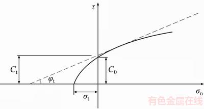
Figure 1 Nonlinear failure criterion in plane ��n�C��n
 (1)
(1)
where C0 denotes the initial cohesion (C0��0) and ��t represents the uniaxial tensile strength of the geomaterial (��t��0). Both the parameters could be determined by experiments via the intercepts of the intensity envelope on the vertical and horizontal axes. The dimensionless parameter m in Eq. (1) is related to the geomaterial properties, which describes the bending degree of the intensity envelope and satisfies m��1.0. When m=1.0, the curve reduces to a straight line, and the nonlinear strength criterion turns out to be a linear Mohr-Coulomb criterion, which is finally shown as
 (2)
(2)
where c=C0 and tan��=C0/��t.
3 Variation analysis of ultimate pullout capacity of a shallow horizontal circular plate anchor under nonlinear M-C failure criterion
3.1 Construction of 3-D failure mechanism of shallow circular plate anchors
Assuming that the geomaterial covering the plate anchor is an ideal homogenous rigid-plastic body, it obeys the nonlinear M-C failure criterion when damaged. The plate anchor is regarded as a rigid body, and there is no relative sliding between the geomaterial and the anchor. The corresponding failure mechanism of the 3-D curve under the limit state of the plate anchor is then determined, as shown in Figure 2. The construction process is as follows. Suppose that there are two velocity discontinuity lines f(x) symmetric about the z-axis and extending along the top edge of the circular plate anchor to the earth surface to form a flared failure surface. Next, make f(x) rotate 180�� around the z-axis, forming a pullout failure mechanism similar to a spatial ��funnel��, which is composed of two circles whose radii are d at the bottom and L at the top and a spatial rotational surface with f(x) as the bus. The volume and side area of the pullout failure mechanism can be solved by the analytic mathematical method. Subsequently, according to the energy consumption calculation method of the upper bound theorem of limit analysis, the work rate of external forces and internal energy dissipation can be calculated [39, 49�C52].

Figure 2 Failure mechanism of circular plate anchor:
3.2 Upper bound calculations of ultimate pullout capacity of shallow horizontal circular plate anchors
In Figure 2, the separation surface of geomaterial failure is regarded as a thin deformation layer with a certain thickness w, where the shear stress and the normal stress satisfy the nonlinear strength failure criterion. In the principle stress space, with the surface of the plastic potential function coinciding with the strength yield, according to the related flow rules, we can obtain
 (3)
(3)
According to the plastic potential theory, we have
 (4)
(4)
where ��ij is the plastic strain rate vector in the deformable body; ��ij is the stress vector; �� denotes the plastic potential function and �� is the plastic factor.
Based on the above equations, the plastic strain rates of the thin separated layer can be obtained by
 (5)
(5)
According to the geometric relationship shown in Figure 2, the plastic strain rates of the thin separated layer of the failure surface can also be represented as
 (6)
(6)
where  .
.
Thus, the expression of the normal stress and the shear stress can be obtained as
 (7)
(7)
Adding up the work rates of the dissipation generated by the shear stress and normal stress, the work rate of internal energy dissipation at any point on the 3-D failure surface could be obtained [50�C52].

 (8)
(8)
Considering the symmetry of the failure mechanism, the work rate of the internal energy dissipation generated on the whole 3-D thin separated layer could be calculated by integrating the above formula along the entire failure surface.

 (9)
(9)
In the velocity field corresponding to the failure mechanism shown in Figure 2, the geomaterial moves up as a rigid body, whose work rate of gravitation can be expressed by its volume as:
 (10)
(10)
where ��(kN/m3) is the bulk density of the geomaterial.
The work rate of the surface overload ��s is
 (11)
(11)
The work rate of the pullout capacity Pu is
 (12)
(12)
According to the principle of virtual work, the work rate of the internal energy dissipation is equal to the work rates of the external forces and thus the following equation is obtained.
 (13)
(13)
Pu can be expressed as

 (14)
(14)
and


Obviously, the formula of �� is a non- homogeneous second-order linear differential equation with constant coefficients. The expression of f(x) can be solved using the analytic method. Thus, the corresponding Euler equation of �� is
 (15)
(15)
The partial derivatives for f(x) and f ��(x) of the �� function can be obtained.
 (16)
(16)
Substituting Formula (16) into Formula (15), we obtain:
 (17)
(17)
Thus,
 (18)
(18)
where c1 and c are undetermined coefficients and c1=a��c.
3.3 Solution of ultimate pullout capacity of shallow horizontal plate anchors based on difference method
By integrating Formula (18), we can obtain the curve function of the failure surface and then obtain the expression of the ultimate pullout capacity Pu. However, the expression in Formula (18) can be integrated only if m is an integer because of its specificity. Otherwise, neither the primitive function nor the expression of the ultimate pullout capacity Pu could be obtained.
To obtain the solution of the ultimate pullout capacity of shallow circular plate anchors with any parameters, we use the theorem of the difference method in the numerical solution of the curve function f(x) of the failure surface. The basic schematic diagram is shown in Figure 3. The expression of curve function f(x) is divided into several micro-segments on the 2-D plane, and each micro-segment can be replaced with a straight line, whose slope is expressed by the derivative function of its end point. With different parameters, according to the boundary conditions, segments are integrated and summed up one by one from the bottom up to obtain the curve function f(x) of failure surface and the shape of 3-D surface after the rotation. In addition, the ultimate pullout capacity Pu of the corresponding plate anchor can be obtained by layered superposition of the integration.

Figure 3 Schematic diagram of difference method
According to the basic concepts of the difference method,
 (19)
(19)
Given the parameters ��, C0, ��t and m, we could obtain the derivative value of any point xi. Suppose each segment of the curve is denoted as  and the derivative value of each point can be regarded as the slope of the connection line from point (xi, f(xi)) to point (xi+1, f(xi+1)). Viewing the small straight line segment as the curve segment of the actual analytic function, we can obtain the following formula according to Formula (19).
 (20)
(20)
Using Formula (20) for the superposition calculation, the f(x) value of each point can be obtained as
 (21)
(21)
Since the exact analytical solution of the curve could not be obtained, the solution of ultimate pullout capacity Pu is deduced in the same manner. First, we must obtain the integral expression of the ultimate pullout capacity Pu(i) of the thin layer corresponding to each small straight line segment.

 (22)
(22)
After the superposition of the ultimate pullout capacity of whole thin layers, the expression of the ultimate pullout capacity of the entire failure mechanism could be obtained.
 (23)
(23)
Based on the above deduction progress, using the mathematical software Matlab for programming, we can obtain the ultimate pullout capacity of the shallow circular plate anchor and its corresponding 3-D failure mechanism with any combination of parameters under the nonlinear M-C criterion.
4 Analysis of parameters and failure mechanism
4.1 Influence of material parameters on ultimate pullout capacity Pu
There are many factors that affect the ultimate pullout capacity of the shallow plate anchor. In this section, we analyse the influence of both different geomaterial parameters and the embedment manner of plate anchors on the ultimate pullout capacity. Suppose that the surface overload is ��s=0�C50 kPa, the uniaxial tensile strength of the geomaterial is ��t=30�C70 kPa, the density of the geomaterial is ��=15�C25 kN/m3, the initial cohesion is C0=10�C30 kPa, the radius of the plate anchor is d=0.5�C1.5 m and the depth of the plate anchor embedded is H=2�C10 m. We plotted the influence curves of the ultimate pullout capacity of the plate anchor with the change of each parameter when the nonlinear coefficient m=1.0�C3.0, as shown in Figures 4�C12.
From Figures 4�C10, the dimensionless parameter m from the nonlinear M-C failure criterion is observed to have a significant effect on the ultimate pullout capacity. With the increase of dimensionless parameter m, the ultimate pullout capacity decreases in a nonlinear manner. Furthermore, the effect of dimensionless parameter m on the ultimate pullout capacity becomes more significant when the depth and radius of the plate anchor, the density and initial cohesion of the geomaterial, the ratio of the initial cohesion to the uniaxial tensile strength and the surface overload increase or when the uniaxial tensile strength decreases. Moreover, with the depth and radius of the plate anchor increasing, the density and initial cohesion of the geomaterial rising, and the surface overload growing, the ultimate pullout capacity of the circular plate anchor increases apparently. In practical engineering, the above measures that promote the stability of the anchor could be applied reasonably. The ultimate pullout capacity of the circular plate anchor can be improved effectively by increasing the initial cohesion and depth, as shown in Figure 11.

Figure 4 Variation curve of Pu with depth of plate anchor and nonlinear parameter m

Figure 5 Variation curve of Pu with radius of plate anchor and nonlinear parameter m

Figure 6 Variation curve of Pu with density of geomaterial and nonlinear parameter m

Figure 7 Variation curve of Pu with uniaxial tensile strength of geomaterial and nonlinear parameter m

Figure 8 Variation curve of Pu with initial cohesion of geomaterial and nonlinear parameter m

Figure 9 Variation curve of Pu with ratio of initial cohesion to uniaxial tensile strength C0/��t and nonlinear parameter m

Figure 10 Variation curve of Pu with surface overload and nonlinear parameter m

Figure 11 Influence curve of different depths on ultimate pullout capacity with initial cohesion changing

Figure 12 Influence curve of different surface overloads on ultimate pullout capacity with density of geomaterial changing
Figure 12 indicates that when the surface overload reaches a certain limit, the ultimate pullout capacity decreases with the increase of density of the geomaterial. Combined with Figures 6 and 17, it is shown that the influence of density of the geomaterial on the ultimate pullout capacity is relatively small, whereas the increase of density of the geomaterial decreases the surface failure range greatly. As the surface overload is large, it will lead to a significant decrease of the pullout capacity. Moreover, Formulas (14) and (23) indicate that the surface overload does not affect the failure mechanism and failure range, this is related to the variation analysis model used in this work. In practical engineering, the surface overload should affect the failure mechanism and range. Thereof, the effect of the surface overload on the failure mechanism and the failure range of the plate anchor have yet to be studied thoroughly.
4.2 Influence of geomaterial parameters on 3-D failure mechanism of shallow circular plate anchor
To analyze the corresponding failure mechanism of geomaterial on top of the plate anchor during the pullout process of the anchor, we considered the influence of the radius and depth of the plate anchor, the initial cohesion, the uniaxial tensile strength and density of the geomaterial as well as the dimensionless parameter m. We plotted the shape of the failure surface of the geomaterial under the change of each single parameter, as shown in Figures 13�C18. Thereof, the uniaxial tensile strength of the geomaterial ��t=30�C70 kPa, the density of the geomaterial ��=15�C25 kN/m3, the radius of the plate anchor d=0.5�C1.5 m, the initial cohesion C0=10�C30 kPa, the depth of the plate anchor H=2�C10 m and the dimensionless parameter m=1.0�C3.0.
From Figures 13�C18, the failure mechanism of the plate anchor subjected to the pullout force is affected greatly by the geometrical size and depth of the plate anchor as well as the geomaterial parameters. As the plate anchor is pulled out and damaged, the 3-D surface of the failure mechanism is formed in the 3-D coordinate system and projected as a symmetrical funnel on the x�Cz plane. Thereof, the dimensionless parameter m determines the shape of failure surface. With the parameter m decreasing, the bending degree of the failure surface also decreases whereas the range of surface damage expands. As m=1.0, the nonlinear M-C failure criterion is transformed into the linear M-C failure criterion with the largest surface damage range and the corresponding failure mechanism is similar to a circular truncated cone. In addition, with the radius or depth of the plate anchor, the initial cohesion, or uniaxial tensile strength increasing, the surface damage range expands. In contrast, with the density of the geomaterial increasing, the surface damage range is scaled down. From Formulas (14) and (23), under the assumption and analysis model in this work, when the plate anchor is pulled out, the surface overload does not affect the shape of failure surface, except for the ultimate pullout capacity.
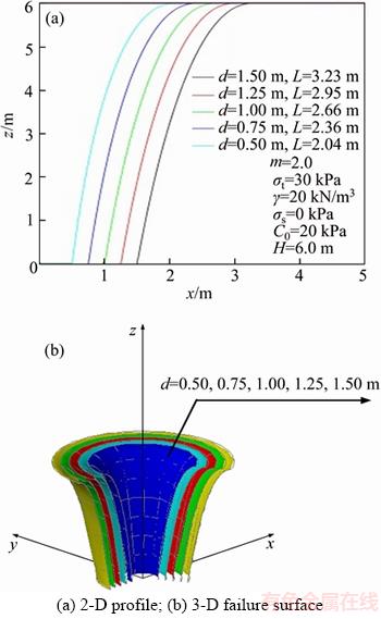
Figure 13 Different radius of plate anchor:
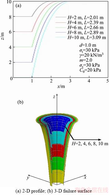
Figure 14 Different depths of plate anchor:
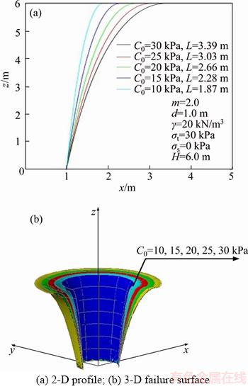
Figure 15 Different initial cohesions:

Figure 16 Different uniaxial tensile strengths of geomaterial:

Figure 17 Different densities of geomaterial:
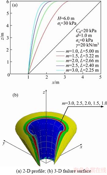
Figure 18 Different nonlinear parameters:
5 Comparison with ultimate pullout capacity and failure mechanism
5.1 Comparison between exact solution and numerical solution to ultimate pullout capacity in specific case of m=2.0
For m=2.0, through Formula (18), the derivative function f'(x) of the curve function of the failure surface f(x) degenerates to a non-exponential expression that is easily solved to obtain the primitive function. For the special case of m=2.0, we adopt two methods to calculate the ultimate pullout capacity of the circular plate anchor. One method is to integrate the derivative function directly and obtain the analytic solution of the curve function by using its boundary condition, followed by taking the analytic solution into the expression of ultimate pullout capacity to obtain the exact solution. The other method is to employ the difference method in Section 3.3 to obtain micro- segments of the failure curve and then obtain the approximate solution of ultimate pullout capacity by layered superposition. The comparison between the two methods would prove the feasibility and effectiveness of the solution method based on difference theory in this work.
For m=2.0, Formula (18) degenerates to a non-exponential expression.
 (24)
(24)
By integration, we could obtain
 (25)
(25)
where c1 and c2 are the constants of the integration that could be determined by the boundary conditions.
From Figure 2, the boundary conditions are shown as:
 (26)
(26)
Substitute Formula (25) into (26) to obtain
 (27)
(27)
Formula (27) contains three unknown variables c1, c2 and L and thus it is unavailable to obtain the solution by two equations. Thus, for analysis, we take a micro-element of the surface [39, 50, 53], whose stress boundary condition satisfies
 (28)
(28)
where
 (29)
(29)
 (30)
(30)
Substituting Formulas (29) and (30) into (28), we obtain the following:

 (31)
(31)
Because the shear stress at the surface is 0, we have the following expression:
 (32)
(32)
Combined with the conditions m��1 and ��t>C0, the following equation is obtained:
 (33)
(33)
Therefore,
 (34)
(34)
Using Formulas (34) into (24), we obtain
 (35)
(35)
Through association of the three nonlinear equations in Formulas (27) and (35), we could use the numerical analysis method to obtain the analytical solution of c1, c2 and L.
With c1, c2, substituting Formulas (24) and (25) into Formula (14), the expression of ultimate pullout capacity could be expressed as

 (36)
(36)
After integration, we obtain


 (37)
(37)
For the radius of the circular plate anchor d=1 m, ��s=0 kN/m2, C0=20 kPa, ��t=30 kPa and ��=20 kN/m3, we determined how the ultimate pullout capacity Pu of the plate anchor and the radius of the top surface of failure mechanism L change with the depth H by using the above two methods, as shown in Figures 19 and 20.

Figure 19 Comparison of ultimate pullout capacities with different depths

Figure 20 Comparison of ranges of failure surface with different depths
As seen in Figures 19 and 20, the approximate solution proved by our method is basically the same as the exact solution. The largest difference between them is smaller than 1%, which could prove the feasibility and effectiveness of the numerical solution based on the difference principle in this work. Moreover, in general cases where the actual parameters of the geomaterial strength criterion do not satisfy m=2.0, our method meets the practical need.
5.2 Comparison between solutions of ultimate pullout capacity Pu by variation method and upper bound method
5.2.1 Upper bound analysis of ultimate pullout capacity of shallow circular plate anchor
Referring to the 2-D failure mechanism of the shallow strip plate anchor proposed by MURRAY et al [3], assuming that the circular plate anchor has axisymmetric properties, the failure mechanism of the ultimate pullout capacity and the corresponding velocity field are shown in Figure 21. According to the geometric relationship shown in Figure 21, we could obtain the geometric elements of the internal and external rigid blocks in the failure mechanism [54].
Regarding the nonlinear M-C failure criterion adopted in this work, when using the upper bound method of limit analysis, we usually introduce the nonlinear shear strength index ct and ��t as the variables obtained by ��the outer tangential line technique��. The tangent equation of Formula (1) is
 (38)
(38)
where the two indices, ct and tan��t denote the slope and the intercept of the tangential line, respectively, as shown in Figure 1. Their expressions are as follows:
 (39)
(39)
 (40)
(40)
Combined with the failure mechanism of the shallow circular plate anchor shown in Figure 21, the energy consumption calculation includes the work rate of the external forces and the internal energy dissipation. Thereof, the work rate of external forces contains the work rate from the ultimate pullout capacity Pu, the surface overload and the geomaterial gravity in the failure mechanism, which are denoted as WPu, Wq and Wsoil, respectively. The internal energy dissipation occurs in the velocity discontinuity surface Sbc_ef and Sad_ef, and the relevant formulas are Gbc_ef and Gad_ef. The detailed deduction of the power of external forces and the internal energy dissipation is presented in Appendix 1.
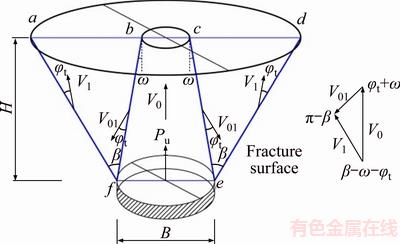
Figure 21 Failure mechanism of shallow circle plate anchor
Using the principle of virtual work, according to the theorem that the work rate of the external forces is equal to the internal energy dissipation rate, the expression of ultimate pullout force Pu could be built.

 (41)
(41)
In the objective function of the ultimate pullout capacity of circular plate anchors shown in Formula (41), except for four known variables, B, H, �� and q, along with ct, which denotes the shear strength corresponding to a tangent of a certain point under the nonlinear failure criterion, the ultimate pullout capacity is also related to the variables ��t, �� and ��. We adopted the sequential quadratic programming (SQP) method to optimize the objective function in Formula (41) to obtain the minimum value of the ultimate pullout capacity.
5.2.2 Comparison between variation method and upper bound method regarding ultimate pullout capacity of shallow circular plate anchors
A plot of the change of the ultimate pullout capacity with the dimensionless parameter m at different depths in the variation method and the upper bound method is shown in Figure 22.
Figure 22 shows that when the dimensionless parameter m=1.0, the 3-D failure mechanism assumed by the variation method degenerates to the circular truncated cone by the upper bound method, and the results from the two methods are basically the same as those shown in Figure 23. However, with the increase of the depth, the difference between the circular truncated cone assumed by the upper bound method for the failure mechanism and the practical failure mechanism is increasingly significant. Figure 24 shows that the calculation result of the variation method is significantly smaller than that of the upper bound method. In the framework of the upper bound method of limit analysis, it is apparent that the variation method outperforms the upper bound method, which is a method similar to the method used in engineering practice.

Figure 22 Comparison between results of variation method and upper bound method at different depths

Figure 23 Comparison of failure mechanism at H=2 m

Figure 24 Comparison of failure mechanism at H=6 m
5.3 Comparison between existing research results and present work based on linear M-C failure criterion
At present, there exist a large number of studies on the pullout capacity of circular anchor plate embedded in sand based on the linear M-C failure criterion. The main methods are the experimental method, numerical simulation method and theoretical analysis method. To prove the effectiveness of this work, the comparison between the existing research results and the present work via calculating the pullout capacity of circular anchor plate when the dimensionless parameter m=1.0 (i.e., the nonlinear M-C failure criterion is degenerated to the linear M-C failure criterion) is presented, as shown in Figure 25. MERIFIELD et al (2006) [55] obtained the numerical solution by adopting the displacement finite element formulation; MERIFIELD et al (2006) [15] and BHATTACHARYA et al (2016) [19] obtained the lower bound solution using the lower bound of the limit analysis; MURRAY (1987) [3] obtained the upper bound solution using the upper limit analysis of rigid body; GHALY et al (1994) [14] obtained the equilibrium solution based on mechanical equilibrium and ILLAMPARUTHI et al (2002) [6] obtained the experimental solution via laboratory experiment when the parameter ��=43��.
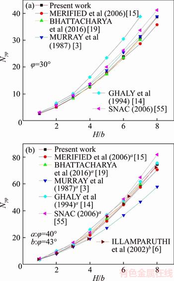
Figure 25 Comparison of N�æ� between existing research results and present work
Based on the linear M-C failure criterion, the pullout capacity of circular anchor plate is expressed by dimensionless coefficient N�æ�:
 (42)
(42)
where Pu (kN) represents the pullout capacity; ��(kN/m3) is the bulk density of the geomaterial; ��(��) is the internal friction angle; d(m) is the diameter of the circular anchor plate and H(m) is the buried depth.
As seen in Figure 25, based on the linear M-C failure criterion, the upper bound solution of this paper adopting the variational method is approximate and consistent with the existing research results, including the numerical solution, the upper bound solution, the lower bound solution, the equilibrium solution and the experimental solution. Moreover, the upper bound solution of this paper is slightly larger than the lower solution of the existing research results, but the maximum error is less than 5%, which can prove the correctness of the results of the variational method.
6 Conclusions
1) The ultimate pullout capacity of the circular plate anchors decreases with the increase of the dimensionless parameter m and the uniaxial tensile strength of the geomaterial, but increases with the increase of the depth and the radius of the plate anchor, the surface overload, the initial cohesion, the geomaterial density and the geomaterial friction angle. When the surface overload exceeds a certain value, the ultimate pullout capacity is affected greatly by it and less by the geomaterial density.
2) The failure mechanism of the geomaterial covering the plate anchor is similar to a symmetric spatial funnel, and its shape mainly depends on the dimensionless parameter m. The surface damage range expands with the increase of the depth and radius of the plate anchor and the initial cohesion, but decreases with the increase of the uniaxial tensile strength and density of the geomaterial.
3) The comparisons show that, in the specific case of m=2.0, the approximate solution based on the variation principle is basically the same as the analytic solution. As m=1.0, the failure mechanism of the variation method degenerates to the circular truncated cone based on the upper bound method, and the results of the two methods are the same completely, thereby proving the effectiveness of the numerical solution of our method which is based on the variation principle.
Appendix 1: Upper bound analysis of ultimate pullout capacity of shallow circular plate anchors
Combined with the failure mechanism of the shallow circular plate anchor in Figure 21, the velocity field of the geomaterial is constructed. Equating V0=1 and according to the velocity triangle relationship (shown in Figure 21), the absolute velocity(V1) and the relative velocity (V01) can be obtained.
 (F1-1)
 (F1-2)
where �� and �� denote the variables introduced from the failure mechanism.
The energy consumption contains the work rate of the external forces and the internal energy dissipation rate.
The work rate of external forces. From Figure 21, we know that, in the assumed failure mechanism, the work rate of external forces contains the work rates from the ultimate pullout capacity Pu, the surface overload, and the geomaterial gravity in the failure mechanism. They are denoted as WPu, Wq and Wsoil.
The work rate of the ultimate pullout capacity Pu, WPu, is shown as follows:
 (F1-3)
where B(m) represents the diameter of the circular anchor.
The work rate of the surface overload contains two parts.

 (F1-4)
where ad and bc denote the diameters of the internal and external circular of the surface damage range, respectively.
The work rate of geomaterial gravity also includes two parts. Considering that the gravity direction of the geomaterial is always vertical and down and the angle between the gravity direction and the movement direction inside the mechanism is �� and outside is ��+��t+�بC��, we have

(F1-5)
where �� (kN/m3) denotes the density of the geomaterial; Vbc_ef is the volume of the inner circular truncated cone and Vadef_bcef is the volume of the outer circular truncated cone that removes the volume of the inner one.
The internal energy dissipation rate. According to the assumption, the circular foundation is a rigid body, and the sliding geomaterial mass under the foundation subgrade is the ideal rigid body. There is no plastic deformation and the internal energy dissipation only occurs on the surface of the velocity discontinuity Sbc_ef and Sad_ef. Therefore, the equations for Gbc_ef and Gad_ef are given below:
 (F1-6)
 (F1-7)
where Sbc_ef is the lateral area of the inner circular truncated cone and Sad_ef is the lateral area of the outer circular truncated cone.
The expression of the ultimate pullout capacity. Using the principle of virtual work, according to the theorem that the work rate of external forces is equal to the internal energy dissipation rate in the failure mechanism, considering the external forces on the boundary, the expression of the ultimate pullout capacity Pu is built as follows:

(F1-8)
References
[1] MEYERHOF G G, ADAMS J I. Ultimate uplift capacity of foundation [J]. Canadian Geotechnical Journal, 1968, 5(4): 225�C244.
[2] DAS B M. Model tests for uplift capacity of foundations in clay [J]. Geomaterials and Foundations, 1978, 18(2): 17�C24.
[3] MURRAY E J, GEDDES J D. Uplift of plate anchors in sand [J]. Journal of Geotechnical Engineering, ASCE, 1987, 113(3): 202�C215.
[4] QIAN P Y, LIU Z D. Distortion and failure character of shallow buried inclined anchors [J]. Chinese Journal of Geotechnical Engineering, 1992, 14(1): 62�C66. (in Chinese)
[5] HE S M. Study on bearing capacity of uplift anchor foundation [J]. Underground Space, 2002, 22(2): 145�C148.
[6] ILAMPARUTHI K, DICKIN E A, MUTHUKRISHNAIAH K. Experimental investigation of the uplift capacity of circular plate anchors in sand [J]. Canadian Geotechnical Journal, 2002, 39(3): 648�C664.
[7] CHU X F, LI Z G, WANG R, ZHU C Q. The test research of anchor��s uplift behavior in calcareous sand [J]. Rock and Soil mechanics, 2002, 23(3): 368�C371. (in Chinese)
[8] ZHU C Q, CHU X F. Calcareous sand in the limits of plate anchor uplift force calculation [J]. Rock and Soil Mechanics, 2003, 24: 153�C158. (in Chinese)
[9] DING P M, XIAO Z B, ZHANG Q L, QIU T. Uplift capacity of plate anchors in sand [J]. Journal of Building Structures. 2003, 24(5): 82�C91.
[10] DICKIN E A, LAMAN M. Uplift response of strip anchors in cohesionless geomaterial [J]. Advances in Engineering Software, 2007, 38(9): 618�C625.
[11] LIU W B. The bearing behavior and calculation of the anti-uplift foundation [M]. Shanghai: Shanghai Jiao Tong University Press, 2007.
[12] BOUAZZA A AND FINLAY T W. Uplift capacity of plate anchors buried in a two-layered sand [J]. G��otechnique, 1990, 40(2): 293�C297.
[13] LIU H Q, HUANG J Z. Vertical uplift capacity of horizontal plate anchors [J]. Geotechnical Engineering Technique, 2007, 21(1): 25�C27.
[14] GHALY A, HANNA A. Ultimate pullout resistance of single vertical anchors [J]. Canadian Geotechnical Journal, 1994, 31(5): 661�C672.
[15] MERIFIELD R S, LYAMIN A V, SLOAN S W. Three-dimensional lower bound solutions for the stability of plate anchors in sand [J]. G��otechnique, 2006, 56(2): 123�C132.
[16] KOUZER K M, KUMAR J. Vertical uplift capacity of equally spaced horizontal strip anchors in sand [J]. International Journal of Geomechanics, ASCE, 2009, 9(5): 230�C236.
[17] KOUZER K M, KUMAR J. Vertical uplift capacity of two interfering horizontal anchors in sand using an upper bound limit analysis [J]. Computers and Geotechnics, 2009, 36(6): 1084�C1089.
[18] KHATRI V N, KUMAR J. Vertical uplift resistance of circular plate anchors in clays under undrained condition [J]. Computers and Geotechnics, 2009, 36(8): 1352�C1359.
[19] BHATTACHARYA P, KUMAR J. Uplift capacity of anchors in layered sand using finite-element limit analysis: Formulation and results [J]. International Journal of Geomechanics, 2016, 16(3): 04015078.
[20] BHATTACHARYA P, KUMAR J. Uplift capacity of strip and circular anchors in soft clay with an overlay of sand layer [J]. Geotechnical and Geological Engineering, 2015, 33(6): 1475�C1488.
[21] KUMAR J, KOUZER K M. Vertical uplift capacity of horizontal anchors using upper bound limit analysis and finite elements [J]. Canadian Geotechnical Journal, 2008, 45(5): 698�C704.
[22] KHATRI V N, KUMAR J. Vertical uplift resistance of circular plate anchors in clays under undrained condition [J]. Computers and Geotechnics, 2009, 36(8): 1352�C1359.
[23] SMITH C C. Limit loads for a shallow anchor/ trapdoor embedded in a non-associative Coulomb soil [J]. G��otechnique, 2012, 62(7): 563�C571.
[24] ROWE R K, DAVIS E H. The behaviour of plate anchors in sand [J]. G��otechnique, 1982, 32(1): 9�C23.
[25] LIU W B, ZHOU J. Partical flow code numerical simulation of extended foundation under the action of uplift loading [J]. Journal of Hydraulic Engineering, 2004, 35(12): 69�C76.
[26] WAND D, HU Y X, RANDOLPH M F. Three-dimensional large deformation finite-element analysis of plate anchors in uniform clay [J]. Journal of Geotechnical and Geoenvironmental Engineering, ASCE, 2010, 136(2): 355�C365.
[27] YU L, LIU J, KONG X J, HU Y X. Three-dimensional numerical analysis of the keying of vertically installed plate anchors in clay [J]. Computers and Geotechnics, 2009, 36(4): 558�C567.
[28] GIAMPA J R, BRADSHAW A S, SCHNEIDER J A. Influence of dilatation angle on drained shallow circular anchor uplift capacity [J]. International Journal of Geomechanics (ASCE), 2017, 17(2): 04016056. DOI: 10.1061/(ASCE) GM.1943-5622.0000725.
[29] HOEK E. Strength of joined rock masses [J]. G��otechnique, 1983, 33(3): 187�C223.
[30] AGAR J G, MORGENSTERN N R, SCOTT J. Shear strength and stress-strain behavior of Athabasca oil sand at elevated temperatures and pressures [J]. Canadian Geotechnical Journal, 1987, 24(1): 1�C10.
[31] SANTARELLI F J. Theoretical and experimental investigation of the stability of the axisymmetric borehole [D]. London: University of London, 1987.
[32] CHEN W F, LIU X L. Limit analysis in geomaterial mechanics [M]. Amsterdam: Elsevier Science, 1990.
[33] MAKSIMOVIC M. Nonlinear failure envelope for geomaterials [J]. Journal of Geotechnical Engineering, ASCE, 1989, 115(4): 581�C586.
[34] BAKER R. Nonlinear Mohr envelopes based on triaxial data [J]. Journal of Geotechnical and Geoenvironmental Engineering, ASCE, 2004, 130(5): 498�C506.
[35] HOEK E, BRAY J W. Rock slope engineering [M]. London: The Institution of Mining and Metallurgy, 1981.
[36] ZHAO L H, LI L, YANG X L, DAN H C, ZOU J F. Calculating method of upper bound for ultimate pullout capacity of vertically loaded strip plate anchors based on nonlinear Mohr-Coulomb failure criterion [J]. Journal of Central South University (Science and Technology), 2009, 40(5): 1444�C1450. (in Chinese)
[37] ZHAO L H, LUO Q, LI L, DAN H C. Ultimate pullout capacity of horizontal rectangular plate anchors [J]. Chinese Journal of Geotechnical Engineering, 2009, 31(9): 1414�C1420.
[38] ZHAO L H, LI L, YANG F, LIU X. Joined influences of nonlinearity and dilation on the ultimate pullout capacity of horizontal shallow plate anchors by energy dissipation method [J]. International Journal of Geomechanics, ASCE, 2011, 11(3): 195�C201.
[39] WANG H T, LI S C, WANG Q, MIAO S J, JIANG B. Limit analysis of ultimate pullout capacity of shallow horizontal strip plate anchor based on nonlinear failure criterion [J]. Engineering Mechanics, 2014, 31(2): 131�C138.
[40] ZHANG X J, CHEN W F. Stability analysis of slopes with general nonlinear failure criterion [J]. International Journal for Numerical and Analytical Methods in Geomechanics, 1987, 11(1): 33�C50.
[41] DRESCHER A, CHRISTOPOULOS C. Limit analysis slope stability with nonlinear yield condition [J]. International Journal for Numerical and Analytical Methods in Geomechanics, 1988, 12(3): 341�C345.
[42] ZHAO L H, CHENG X, DAN H C, TANG Z P, ZHANG Y B. Effect of vertical earthquake component on the permanent seismic displacement of soil slopes based on the nonlinear Mohr-Coulomb failure criterion [J]. Soil and Foundations, 2017, 57(2): 237�C251.
[43] DENG D P, LI L, ZHAO L H. Limit equilibrium analysis for rock slope stability using basic Hoek�CBrown strength criterion [J]. International Journal for Numerical and Analytical Methods in Geomechanics, 2017, 24(9): 2154�C2163.
[44] COLLINS I F, GUNN C I, PENDER M J, WANG Y. Slope stability analyses for materials with nonlinear failure envelope [J]. International Journal for Numerical and Analytical Methods in Geomechanics, 1988, 12(6): 533�C550.
[45] TANG G P, ZHAO L H, LI L, CHEN J Y. Combined influence of nonlinearity and dilation on slope stability evaluated by upper-bound limit analysis [J]. Journal of Central South University, 2017, 24(7): 1602-1611.
[46] ZHAO L H, LI L, YANG F, LUO Q, LIU X. Upper bound analysis of slope stability with nonlinear failure criterion based on strength reduction technique [J]. Journal of Central South University of Technology, 2010, 17(4): 836�C844.
[47] ZHAO L H, YANG F, ZHANG Y B, DAN H C, LIU W Z. Effects of shear strength reduction strategies on safety factor of homogeneous slope based on a general nonlinear failure criterion [J]. Computers and Geotechnics, 2015, 63: 215�C228.
[48] ZHAO L H, CHENG X, LI L, CHEN J Q, ZHANG Y B. Seismic displacement along a log-spiral failure surface with crack using rock Hoek-Brown failure criterion [J]. Soil Dynamics and Earthquake Engineering, 2017, 99(12): 74�C85.
[49] HUANG F, YANG X L, LING T H. Prediction of collapsing region above deep spherical cavity roof under axis-symmetrical conditions [J]. Rock Mechanics and Rock Engineering, 2014, 47: 1511�C1516.
[50] FRALDI M, GUARRACINO F. Limit analysis of collapse mechanisms in cavities and tunnels according to the Hoek-Brown failure criterion [J]. International Journal of Rock Mechanics and Mining Sciences, 2009, 46(4): 665�C673.
[51] FRALDI M, GUARRACINO F. Analytical solutions for collapse mechanisms in tunnels with arbitrary cross sections [J]. International Journal of Solids and Structures, 2010, 47(2): 216�C223.
[52] FRALDI M, GUARRACINO F. Limit analysis of progressive tunnel failure of tunnels in Hoek�CBrown rock masses [J]. International Journal of Rock Mechanics and Mining Sciences, 2012, 50(2): 170�C173.
[53] HUANG F, YANG X L, ZHAO L H, HUANG K. Upper bound solution of ultimate pullout capacity of strip plate anchor based on Hoek-Brown failure criterion [J]. Rock and Soil Mechanics, 2012, 33(1): 183�C188, 194. (in Chinese)
[54] TAN Y G, ZUO S, HU S H, YANG X P. Study on the ultimate pullout capacity of 3-D shallow circle plate anchors [J]. Journal of Railway Science and Engineering, 2017, 14(6): 1166�C1173. (in Chinese)
[55] MERIFIELD R S, SLOAN S W. The ultimate pullout capacity of anchors in frictional soils [J]. Canadian Geotechnical Journal, 2006, 43(8): 852�C868.
(Edited by FANG Jing-hua)
���ĵ���
������Mohr-Coulomb�ƻ�����dz����άԲ��ê�弫������������
ժҪ�����ڷ�����Mohr-Coulombǿ�������������������dz��ˮƽԲ��ê����ܼ�������ʱ�Ϸ��������ά��Գ��ƻ����ƣ����ñ��ԭ�����Ƶ�����ά��Գ��ƻ�������ƽ����ͶӰ�����ĵ����������ò��ԭ���������������߽��������ƻ���ԭ����������֮��Ӧ�ļ�������������ֵ��𣻽�һ�������˷�����MC�����仯��Բ��dz��ê�弫���������ƻ�ģʽ��Ӱ����ɡ����������Բ��ê�弫�������������ٲ���m���������С��ê�����ê��뾶���ر����ء���ʼճ�����������ض��Լ�����Ħ���ǵ���������������嵥�Ό��ǿ�ȵ��������С��Բ��ê���Ϸ������ƻ���ʶԳƵĿռ�©����̬��������״��Ҫȡ���������ٲ���m���ر��ƻ���Χ��ê��뾶��ê�������ʼճ��������������������嵥�Ό��ǿ�ȡ������ضȵ��������С���������ٲ���m=2.0ʱ�����������£�����������ȷ������ֵ��Աȷ���֤���˱��Ļ��ڲ�ַ�ԭ����ֵ���Ŀ����Ժ���Ч�ԡ�ͬʱ���Աȷ����˱�ַ��������ļ��������������������ڼ������������ۿ���ڣ���ַ�����������������������
�ؼ��ʣ�dz��Բ��ê�壻������������ַ�����������MC�ƻ�����������
Foundation item: Project(51478477) supported by the National Natural Science Foundation of China; Project(2016CX012) supported by the Innovation-driven Project of Central South University, China; Project(2014122006) supported by the Guizhou Provincial Department of Transportation Foundation, China
Received date: 2017-06-29; Accepted date: 2018-02-07
Corresponding author: DENG Dong-ping, PhD, Lecturer; Tel: +86�C13975150476; E-mail: dengdp851112@126.com; ORCID: 0000- 0002-0145- 8756; ZHAO Lian-heng, PhD, Professor; Tel: +86�C13755139425; E-mail: zlh8076@163.com; ORCID: 0000-0002-8406-5973

