����Գ���Сƽ��֦���������ೡ��ģ��
��Դ�ڿ����й���ɫ����ѧ��(Ӣ�İ�)2018���2��
�������ߣ���־ ���� ���غ� ������ ����÷ �����
����ҳ�룺290 - 297
�ؼ��ʣ��ೡ������ǿ�������ԣ�Сƽ��֦����Wulff ���ۣ�����ٶȣ��Գ���
Key words��phase field method; strong anisotropy; faceted dendrite; Wulff theory; tip velocity; symmetry
ժ Ҫ������һ����Ч�����ೡģ����ģ��Сƽ��֦��������ò��ͨ����ģ�ͷֱ��о������С����������ֵ�������Ͷȼ���ͬ�ضԳ��Զ�Сƽ��֦��������ò��Ӱ�졣�������������ʱ������ƣ���������Ϊ���ضԳ��Ե�Сƽ����ò��������ߴ����640��640ʱ��Сƽ����ò����ģ�������С��Ӱ�졣���Ÿ�������ֵ�����ӣ�Сƽ��֦���ļ���ٶ�����һ������ֵ������С�����Ź����Ͷȵ����ӣ����˴�һ��Բ���ݻ�Ϊ�����Сƽ��֦����ò������Wulff���ۺͶ�Ӧ��Сƽ��Գ���ģ����òͼ��֤���������ģ������Ч�ģ����ܹ���չ�������ضԳ��Եľ���������ģ�⡣
Abstract: A numerical simulation based on a regularized phase field model is developed to describe faceted dendrite growth morphology. The effects of mesh grid, anisotropy, supersaturation and fold symmetry on dendrite growth morphology were investigated, respectively. These results indicate that the nucleus grows into a hexagonal symmetry faceted dendrite. When the mesh grid is above 640��640, the size has no much effect on the shape. With the increase in the anisotropy value, the tip velocities of faceted dendrite increase and reach a balance value, and then decrease gradually. With the increase in the supersaturation value, crystal evolves from circle to the developed faceted dendrite morphology. Based on the Wulff theory and faceted symmetry morphology diagram, the proposed model was proved to be effective, and it can be generalized to arbitrary crystal symmetries.
Trans. Nonferrous Met. Soc. China 28(2018) 290-297
Zhi CHEN1, Pei CHEN1, He-he GONG2, Pei-pei DUAN1, Li-mei HAO3, Ke-xin JIN1
1. Department of Applied Physics, School of Science, Northwestern Polytechnical University, Xi��an 710129, China;
2. School of Software and Microelectronics, Northwestern Polytechnical University, Xi��an 710129, China;
3. Department of Applied Physics, School of Science, Xi��an University of Science and Technology, Xi��an 710054, China
Received 30 November 2016; accepted 17 May 2017
Abstract: A numerical simulation based on a regularized phase field model is developed to describe faceted dendrite growth morphology. The effects of mesh grid, anisotropy, supersaturation and fold symmetry on dendrite growth morphology were investigated, respectively. These results indicate that the nucleus grows into a hexagonal symmetry faceted dendrite. When the mesh grid is above 640��640, the size has no much effect on the shape. With the increase in the anisotropy value, the tip velocities of faceted dendrite increase and reach a balance value, and then decrease gradually. With the increase in the supersaturation value, crystal evolves from circle to the developed faceted dendrite morphology. Based on the Wulff theory and faceted symmetry morphology diagram, the proposed model was proved to be effective, and it can be generalized to arbitrary crystal symmetries.
Key words: phase field method; strong anisotropy; faceted dendrite; Wulff theory; tip velocity; symmetry
1 Introduction
Interfacial energy anisotropy and mobility reflect the crystal structure of interfaces in materials. The crystallographic anisotropy has an important effect on the evolution dynamics and the final morphology structures in materials processing [1,2]. In particular, the anisotropy allows for the simulation of dendrite growth branches in solidification problems [3,4]. When anisotropy is weak for solid/liquid interfaces in most metallic materials, strong anisotropy often leads to facet interface structures such as in silicon, snowflakes or smooth surfaces. Faceted patterns appear in advanced and technological materials [5]. Faceted dendrites have attracted much attention due to their unique crystal structures particularly [6-9]. For example, on account of their aesthetics, snowflakes have attracted considerable interest for decades [10]. While robust theoretical interpretations of facet equilibrium shapes exist, the dynamical aspects of faceted pattern formation are still less understood. Thus, it is important to understand and investigate the mechanism by numerical simulation.
The most significant computational advantages of phase field method are that the explicit tracking of the interface is unnecessary, the interface curvature, anisotropy and kinetics parameters are implicitly incorporated in the phase field equation, and the phase field method has been proved to be a powerful tool for microstructure evolution simulation [11-16]. The method was developed by KARMA and RAPPEL [17] in 1996 for solidification of pure substances and later generalized by KARMA [18] for alloy solidification. However, in the early time, phase field method was mainly used to study the dendrite growth with weak anisotropy value [4,18]. When the anisotropy is so sufficiently strong missing orientations occur and sharp corners form in the Wulff shape [19-21]. This becomes ill-posed and reduces to un-regularized phase field equations. In order to recover accurately equilibrium shapes with corners due to missing orientations, in 2001, EGGLESTON et al [22] dealt with the ill-posedness through regularizing convexifying anisotropic surface energy, and simulated facet equilibrium shape with strong anisotropic interfacial energy. In an alternative phase-field approach, SUZUKI et al [23] simulated faceted crystal growth of silicon from the undercooled melt of silicon�Cnickel alloys. Recently, there also have been a number of attempts to regularize the phase-field equation [24-28]. For example, LIN et al [27] proposed a simplified anisotropic function, and then extended it to a 3D model.
In this work, based on Eggleston model [22], an effective regularized phase field model was presented to model faceted structure with six-fold symmetry, and the effects of mesh grid, anisotropy parameters, and supersaturation on faceted dendrite growth morphology were examined in detail. Furthermore, the fundamental idea of regularizing phase field model can be extended to generalize faceted dendrite morphology with arbitrary symmetries.
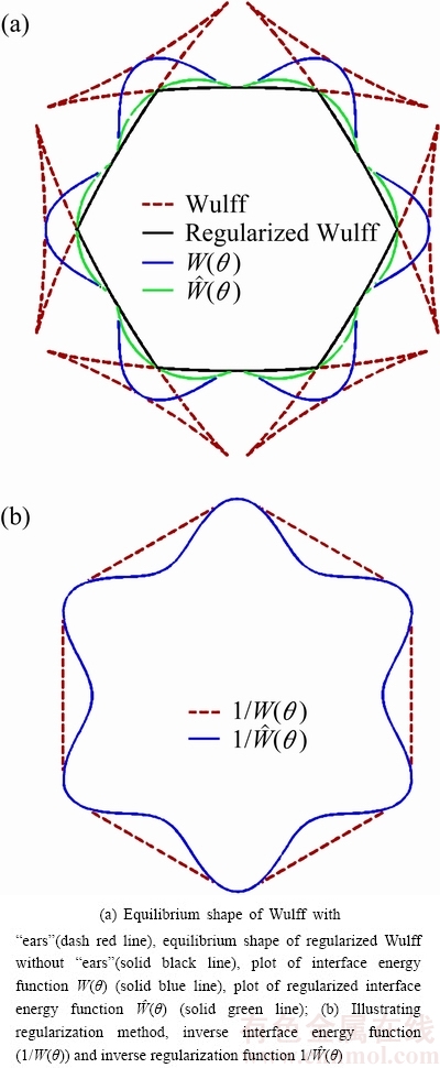
Fig. 1 Parametric plots
2 Phase field model
The equilibrium condition at solid/liquid interface is obtained by the Gibbs-Thomson equation [22]:
 (1)
(1)
where R(��) is the curvature radius of the solid/liquid interface, W(��)(=W0a(��)) is the interface thickness to be anisotropic, a(��)(=1+��cos(6��)) is an anisotropic interface energy function, �� is the dimensionless anisotropy parameter, 6 is the folds of symmetry, f L and f S are the free energy densities of liquid and solid phases, respectively. When �á�1/35, two sides of Eq. (1) are positive, and crystal morphology is smooth and continuity. When ��>1/35, the left side of Eq. (1) is negative as a result of the missing orientations, and discontinuous interface, which occurs concave similar to ��ears��. Besides, Eq. (1) can calculate the equilibrium shape [2,3] for two dimensions in parametric form as
x=W(��)cos ��-W��(��)sin �� (2)
y=W(��)sin ��-W��(��)cos �� (3)
Figure 1 shows the parametric plots for Wulff shape under different conditions. The unregularized Wulff shape is presented in dash red in Fig. 1(a). As shown for one typical strong anisotropy value, the equilibrium shape develops into sharp corners, and the high energy orientation for ��ears�� parts is missing. In order to simulate dendrite growth with strong anisotropy value, these ��ears�� must be removed, and the equation needs to be regularized. As seen in Fig. 1(b), missing orientations in the equilibrium shape occur when the reciprocal W(��) plot becomes concave. Therefore, in order to regularize the phase field equations, the interface energy within these missing orientations were regularized referring to method of EGGLESTON et al [22], as follows:

 (4)
(4)
As illustrated in Ref. [2], it replaces the anisotropy function in these regimes by choosing appropriately circular sections, which is shown in Fig. 1(b) for the case of six-fold symmetry. Where ��m is the first missing orientation angle of the equilibrium shape, and it is calculated through Eq. (5) by standard Newton iteration method:
W(��m)sin ��m+W��(��m)cos ��m=0 (5)
Based on Eq. (4) and regularization model by EGGLESTON et al [22], effective regularized phase field equations are presented to model faceted dendrite shape:
For  , and i=0, 3,

 (6)
(6)
For , and i=1, 4,


 (7)
(7)
For , and i=2, 5,


 (8)
(8)
For  , and i=0-5,


 (9)
(9)
where  represents the phase field parameter, =1 represents the bulk solid phase, =-1 represents the bulk liquid phase, the phase field parameter varies smoothly between two bulk values within the diffuse interface region, ��(��)(=��0a(��)) is a relaxation time of phase field, ��(=arctan
 ) is the angle of the horizontal axis and the direction normal to the interface, and t is time.
The anisotropic and dimensionless forms of solute isothermal equations with ATC are given by [9]

 (10)
(10)
where  is anti-trapping current expression [29,30], k is the molar partition coefficient, U represents the solute field, and D is the solute diffusivity in the liquid phase. All parameters in Eqs. (6)-(10) are dimensionless.
Using a suitable asymptotic expansion, the capillary length d0 and the kinetic coefficient expressions �� are related to the phase field equation in Ref. [18].
3 Numerical simulation
3.1 Initial and boundary conditions
An initial crystal radius is assumed to be r, and crystal exists at the center of square simulation domain. The left, right, top and bottom domain surfaces are treated as symmetrical closed boundaries. The initial phase field and supersaturation are taken as =1, U=0 in the solid and =-1, U=�� elsewhere in the domain.
3.2 Simulation method
Equations (6)-(10) are solved by standard finite difference method, time stepping ��t is by standard explicit Euler scheme, and  using a nine-point formula with nearest and next nearest neighbors, which reduces the grid anisotropy [30,31]. For convenience, the following parameters are chosen: time step ��t=0.008, space step ��x=��y=0.4, ��0=1, W0=1, ��=6.383, ��=-0.45, D=2, d0=0.277. Unless otherwise state, these parameters are not varied.
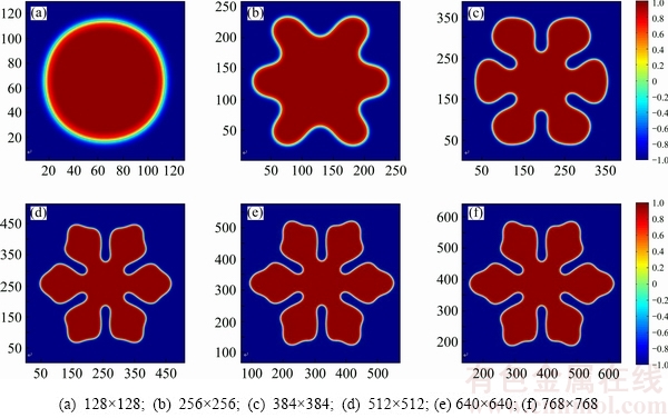
Fig. 2 Crystal growth shape of six different mesh grids at t=60000��t
Various mesh grids are presented to show whether the simulation results are convergent. Figure 2 shows the dendrite growth shape of different mesh grids at t=60000��t. As shown in Fig. 2(a), when mesh grid is 128��128, the initial crystal nucleus cannot grow freely in the grid space, the boundary effect restricts its growth strongly, and the crystal keeps growing on one circle shape. When the mesh grid is increased up to 256��256, the anisotropy dendrite growth shape can be found in Fig. 2(b), but the shape is still affected by the boundary size. If the mesh grid continues to increase to 384��384 (Fig. 2(c)), it can be seen that crystal obviously grows into hexagonal facet shape. When the mesh grid moves to 512��512 (Fig. 2(d)), the grid boundary effects on the dendrite shape become small, six-fold dendrite arms have the same tip shape. If the mesh grid is further increased, Figs. 2(e) and (f) show the evolution of the morphologies, the hexagonal shape is shown in the same mesh grid space 512��512, where no visible discrepancy exists in the shape. To quantify the discrepancy between the two shapes, a relative difference is defined as follows. The tip growth velocities of six different mesh grids are shown in Fig. 3. As presented, with time moving on, the velocity decreases to each corresponding steady value from one same original value. When increasing the mesh grid, the steady velocity gradually convergences to one value. In order to check the value and get a proper calculation mesh grid, an inserted figure is presented in Fig. 3. From the high magnification figure, it can be seen that when the mesh grid increases to 512��512, the steady velocity is near to the convergence value, but the difference between Fig. 2(d) and Figs. 2(e) and (f) can not be seen. However, the tip velocity under mesh grid of 640��640 is equal to that of 768��768, which indicates that mesh grid has no influence on dendrite growth shape when mesh grid is above 640��640. Thus, the mesh grid of 640��640 is adopted in the following section.
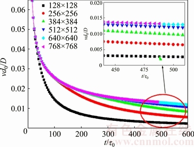
Fig. 3 Dendrite arm tip growth velocity versus time for various mesh grids
4 Results and discussion
4.1 Faceted dendrite shape with six-fold symmetry
Figure 4 shows numerical simulation results at t=70000��t. Figure 4(a) shows the shape evolution of hexagonal facet interface at t=70000��t, where every contour is at an interval of 10000��t. With time going on, crystal gradually grows into facet dendrite, and the cusp curvature between two dendrite arms becomes deeper. Notice that in Fig. 4(b) crystal grows into a hexagonal facet shape, and secondary dendrite arms cannot be found, which is not similar to the non-faceted dendrite shape [4]. Figure 4(c) shows the solute field shape, which is similar to the shape of Fig. 4(b).
The tip velocity versus time curve in above conditions is plotted in Fig. 5(a). As shown in Fig. 5(a), a normal trend is that the initial high tip velocity falls to a nearly steady state value. The inserting phase field figures show the progress of shape evolution. Furthermore, the solidus concentration profiles in solid and liquid along one central dendrite axis grid can show the change of solute field (Cs/C�� means the ratio of solidus concentration and initial given concentration C��, where C�� is the value of the concentration C far from the interface). This means that the solidus concentration has one low concentration along the dendritic arm, arrives to the interface, and the concentration that increases to one maximum value for the solute is released, corresponding to the growth of dendrite, then to one general concentration in the supersaturation liquid. Compared with non-faceted dendrite growth [29,31], the change of concentration is not sharp, because no secondary dendrite arms make solute release less.
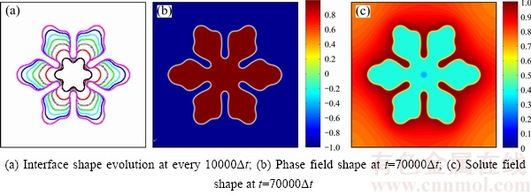
Fig. 4 Hexagonal facet shape
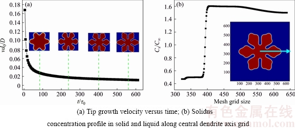
Fig. 5 Tip growth velocity and solidus concentration profiles of six-fold facet shape
4.2 Effect of anisotropy parameter
Figure 6 illustrates dendrite tip steady velocities at various strong anisotropy values. As seen from the Fig. 6, with increasing anisotropy value, steady state tip velocities have an increasing trend, touch to one balance value, and then decrease. The fact that the tip velocity decreasing with increasing anisotropy value results from the increase in the range of missing orientations. Notice that faceted dendrite shape has no significant change, which is shown in Fig. 7. For the difference of shape, it can also be presented by the Wulff theory equilibrium shape in Fig. 8, as shown in Fig. 8(a), the main hexagonal shape has the near same area shape with ��ear��, only has different sizes of the missing orientations ears parts. In order to clear the difference, one part of the Wulff shape is magnified in Fig. 8(b), which shows that the main area decreases with increasing the strong anisotropy. Compared with Fig. 8(b), the further magnified figure is illustrated in Fig. 8(c), it can be found that the tip location becomes larger with increasing the strong anisotropies from 0.0287 to 0.04, then, increasing the anisotropies more, the tip location changes to be smaller. Combining Fig. 6 with Fig. 8, the reason for the decrease in tip velocity change is that the range of missing orientations is increased and more solutes are released at the anisotropy values of 0.0287-0.04, which directly induces the increase of growth velocity. However, when the anisotropy value is more than 0.04, the missing orientations increase quickly, while solute releasing increases slowly, then the final result is that the tip location becomes smaller, and a decreasing trend forms with further increasing the anisotropy value.
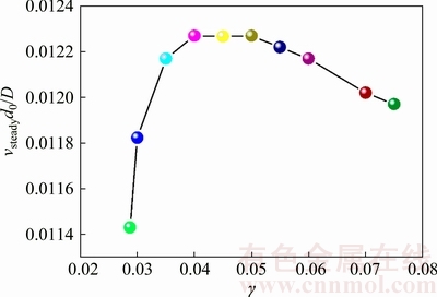
Fig. 6 Steady tip velocities at different strong anisotropies
4.3 Effect of supersaturation
Figure 9 shows the tip growth velocity and steady tip velocity of six-fold facet shape. The steady velocity value comes from the inserting figure. When the undercooling (��) is fixed by the given model, thus the supersaturation is more important for the faceted dendrite growth, which can reflect the influence degree between them.
As shown, one circular seed only grows to a round crystal when ��2 is 0.0225. With increasing super- saturation value, the influence of solute field boosts, interface stability becomes worse, and fractal begins to appear and grow more, finally grows to one hexagonal facet shape when ��2 is 0.1225. Furthermore, the hexagonal shape evolves to one developed facet shape. This is because the larger the supersaturation value is, the more greatly the phase field varies, which enhances the degree of anisotropy growth, renders much more disturbance at the interface, leading to a non-circular crystal.
4.4 Dendrite shape with different symmetries
In order to illustrate the fact that the formulation is general and can be applied to arbitrary crystal symmetries, through changing the anisotropy function a(��), different models corresponding to different crystalline symmetries can be obtained. Using the regularized idea it is proved that the model can be extended to other symmetries facet dendrite growth conditions. Figure 10 shows the facet dendrite evolution diagram. As shown in Fig. 10, there are three concentric circles, the calculation results are placed on these circles. For illustrating the fact that this method is effective, we choose three-, six-, nine-, twelve-, and fifteen-fold symmetries models. It can be seen that the simulation facet shapes with different symmetries shape are in excellent agreement with their analytic Wulff shape. Exactly, these circles have one nucleus with radius of 15. The first circle is the regularized Wulff equilibrium shape, the initial phase field shape for different symmetries is compared with the Wulff shapes on the second circle, and this figure shows that there is actually no observable discrepancy between initial phase field shape and Wulff theory equilibrium shape. The third circle is the typical faceted dendrite shape when simulation time of moving on is enough, which furthermore demonstrates that this method can be used to simulate arbitrary symmetries crystal shape.
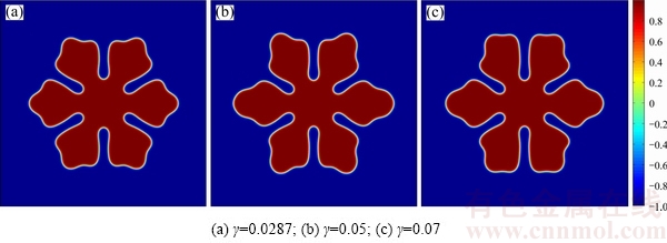
Fig. 7 Faceted dendrite shape at different strong anisotropies
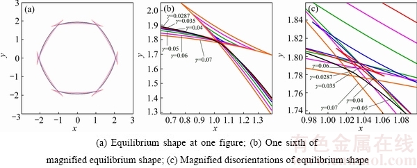
Fig. 8 Wulff theory equilibrium shape versus different strong anisotropies
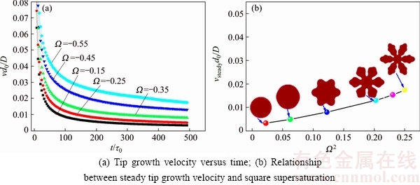
Fig. 9 Tip growth velocity and steady tip velocity of six-fold facet shape
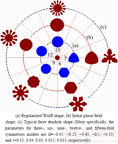
Fig. 10 Diagram of faceted dendrite shape with different symmetries
5 Conclusions
1) For the six-fold symmetry structure, when mesh grid is greater than 640��640, the mesh grid has no influence on faceted dendrite growth shape.
2) With increasing strong anisotropy value, the tip steady velocities are enhanced. When the anisotropy value varies between 0.04 and 0.06, the tip velocities arrive to one balance value, and then the tip velocities have a decreasing trend with further increasing the anisotropy value. With increasing the square supersaturation, tip velocities have a nonlinear increasing phenomenon, and hexagonal facet shape evolves into developed dendrite structure.
3) Importantly, based on the regularized idea, the revised phase field equation is proposed, one evolution diagram is plotted by three-, six-, nine-, twelve- and fifteen-fold symmetries shapes. Both the regularized Wulff equilibrium shape and modeling facet shape all demonstrate that this method has sufficient ability to simulate arbitrary crystal symmetries structures.
References
[1] ZHANG L, SHEN Y, ZHANG L, WANG Y M, XIONG X C, ZHANG L T. Competing effects of interface anisotropy and isotropic driving force on the growth of steady-state shape in phase-field modeling [J]. Computational Materials Science, 2016, 111: 313-321.
[2] FLECK M, MUSHONGERA L, PILIPENKO D, ANKIT K, EMMERICH H. On phase-field modeling with a highly anisotropic interfacial energy [J]. The European Physical Journal Plus, 2011, 126(10): 1-11.
[3] AMOOREZAEI M, GUREVICH S, PROVATAS N. Orientation selection in solidification patterning[J]. Acta Materialia, 2012, 60(2): 657-663.
[4] HAXHIMALI T, KARMA A, GONZALES F, RAPPAZ M. Orientation selection in dendritic evolution [J]. Nature Materials, 2006, 5(8): 660-664.
[5] FUJIWARA K, MAEDA K, USAMI N, NAKAJIMA K. Growth mechanism of Si-faceted dendrites [J]. Physical Review Letters, 2008, 101(5): 055503.
[6] CHEN G Y, LIN H K, LAN C W. Phase-field modeling of twin-related faceted dendrite growth of silicon [J]. Acta Materialia, 2016, 115: 324-332.
[7] SUZUKI T, KIM S G, KIM W T. Two-dimensional facet crystal growth of silicon from undercooled melt of Si-Ni alloy [J]. Materials Science and Engineering A, 2007, 449: 99-104.
[8] YUAN Xun-feng, LIU Bao-ying, LI Chun, ZHOU Chun-sheng, DING Yu-tian. Simulation of facet dendrite growth with strong interfacial energy anisotropy by phase field method [J]. Journal of Central South University, 2015, 22: 855-861.
[9] LIN H K, CHEN C C, LAN C W. Adaptive three-dimensional phase-field modeling of dendritic crystal growth with high anisotropy [J]. Journal of Crystal Growth, 2011, 318(1): 51-54.
[10] KELLY J G, BOYER E C. Physical improvements to a mesoscopic cellular automaton model for three-dimensional snow crystal growth [J]. Crystal Growth & Design, 2014, 14(3): 1392-1405.
[11] KOBAYASHI R. Modeling and numerical simulations of dendritic crystal growth [J]. Physica D: Nonlinear Phenomena, 1993, 63(3-4): 410-423.
[12] LIAO Hai-hong, LIANG Min-jie, BAI Pei-kang. Quantitative calculation on atomic site occupation during precipitation of Ni3(Al1�CxFex) by microscopic phase-field study [J]. Transactions of Nonferrous Metals Society of China, 2016, 26(4): 1073-1078.
[13] CHEN L Q. Phase-field models for microstructure evolution [J]. Annual Review of Materials Research, 2002, 32(1): 113-140.
[14] STEINBACH I. Phase-field models in materials science [J]. Modelling and Simulation in Materials Science and Engineering, 2009, 17(7): 073001.
[15] ASTA M, BECKERMANN C, KARMA A, KURZ W, NAPOLITANO R, PLAPP M, PURDY G, RAPPAZ M, TRIVEDI R. Solidification microstructures and solid-state parallels: Recent developments, future directions [J]. Acta Materialia, 2009, 57(4): 941-971.
[16] KARMA A, TOURRET D. Atomistic to continuum modeling of solidification microstructures [J]. Current Opinion in Solid State and Materials Science, 2016, 20(1): 25-36.
[17] KARMA A, RAPPEL W J. Phase-field method for computationally efficient modeling of solidification with arbitrary interface kinetics [J]. Physical Review E, 1996, 53(4): R3017.
[18] KARMA A. Phase-field formulation for quantitative modeling of alloy solidification [J]. Physical Review Letters, 2001, 87(11): 115701.
[19] SALVALAGLIO M, BACKOFEN R, BERGAMASCHINI R, MONTALENTI F, VOIGT A. Faceting of equilibrium and metastable nanostructures: A phase-field model of surface diffusion tackling realistic shapes [J]. Crystal Growth & Design, 2015, 15(6): 2787-2794.
[20] WISE S, KIM J, LOWENGRUB J. Solving the regularized, strongly anisotropic Cahn�CHilliard equation by an adaptive nonlinear multigrid method [J]. Journal of Computational Physics, 2007, 226(1): 414-446.
[21] SEKERKA R F. Analytical criteria for missing orientations on three-dimensional equilibrium shapes[J]. Journal of Crystal Growth, 2005, 275(1): 77-82.
[22] EGGLESTON J J, MCFADDEN G B, VOORHEES P W. A phase-field model for highly anisotropic interfacial energy [J]. Physica D: Nonlinear Phenomena, 2001, 150(1): 91-103.
[23] SUZUKI T, KIM S G, KIM W T. Two-dimensional facet crystal growth of silicon from undercooled melt of Si-Ni alloy [J]. Materials Science and Engineering A, 2007, 449: 99-104.
[24] DEBIERRE J M, KARMA A, CELESTINI F, GUE��RIN R. Phase-field approach for faceted solidification [J]. Physical Review E, 2003, 68(4): 041604.
[25] LEVITAS V I, WARREN J A. Phase field approach with anisotropic interface energy and interface stresses: Large strain formulation [J]. Journal of the Mechanics and Physics of Solids, 2016, 91: 94-125.
[26] QIN R S, BHADESHIA H. Phase-field model study of the effect of interface anisotropy on the crystal morphological evolution of cubic metals [J]. Acta Materialia, 2009, 57(7): 2210-2216.
[27] LIN H K, CHEN C C, LAN C W. Adaptive three-dimensional phase-field modeling of dendritic crystal growth with high anisotropy [J]. Journal of Crystal Growth, 2011, 318(1): 51-54.
[28] BURMAN E, RAPPAZ J. Existence of solutions to an anisotropic phase-field model [J]. Mathematical Methods in the Applied Sciences, 2003, 26(13): 1137-1160.
[29] RAMIREZ J C, BECKERMANN C, KARMA A, DIEPERS H J. Phase-field modeling of binary alloy solidification with coupled heat and solute diffusion [J]. Physical Review E, 2004, 69(5): 051607.
[30] MULLIS A M, ROSAM J, JIMACK P K. Solute trapping and the effects of anti-trapping currents on phase-field models of coupled thermo-solutal solidification [J]. Journal of Crystal Growth, 2010, 312(11): 1891-1897.
[31] CHEN Zhi, CHEN Chang-le, HAO Li-mei. Numerical simulation for isothermal dendritic growth of succinonitrile-acetone alloy [J]. Transactions of Nonferrous Metals Society of China, 2008, 18(3): 654-659.
�� ־1���� ��1�����غ�2��������1������÷3�������1
1. ������ҵ��ѧ ��ѧԺ Ӧ������ϵ������ 710129��
2. ������ҵ��ѧ ����������ѧԺ������ 710129��
3. �����Ƽ���ѧ ��ѧԺ Ӧ������ϵ������ 710054
ժ Ҫ������һ����Ч�����ೡģ����ģ��Сƽ��֦��������ò��ͨ����ģ�ͷֱ��о������С����������ֵ�������Ͷȼ���ͬ�ضԳ��Զ�Сƽ��֦��������ò��Ӱ�졣�������������ʱ������ƣ���������Ϊ���ضԳ��Ե�Сƽ����ò��������ߴ����640��640ʱ��Сƽ����ò����ģ�������С��Ӱ�졣���Ÿ�������ֵ�����ӣ�Сƽ��֦���ļ���ٶ�����һ������ֵ������С�����Ź����Ͷȵ����ӣ����˴�һ��Բ���ݻ�Ϊ�����Сƽ��֦����ò������Wulff���ۺͶ�Ӧ��Сƽ��Գ���ģ����òͼ��֤���������ģ������Ч�ģ����ܹ���չ�������ضԳ��Եľ���������ģ�⡣
�ؼ��ʣ��ೡ������ǿ�������ԣ�Сƽ��֦����Wulff ���ۣ�����ٶȣ��Գ���
(Edited by Wei-ping CHEN)
Foundation item: Projects (11102164, 11304243) supported by the National Natural Science Foundation of China; Project (2014JQ1039) supported by the Natural Science Foundation of Shannxi Province, China; Project (3102016ZY027) supported by the Fundamental Research Funds for the Central Universities of China; Project (13GH014602) supported by the Program of New Staff and Research Area Project of NWPU, China
Corresponding author: Zhi CHEN; Tel: +86-29-88431664; E-mail: c2002z@nwpu.edu.cn
DOI: 10.1016/S1003-6326(18)64662-X

