
Deposition of chromium aluminum nitride coatings by arc ion plating
ZHANG Shu-juan(张淑娟)1, LI Ming-sheng (李明升)1, FENG Chang-jie(冯长杰)2,
LIU Ting-zhi(刘庭芝) 1, DUO Shu-wang(多树旺) 1
1. Jiangxi Key Laboratory of Surface Engineering, Jiangxi Science and Technology Normal University, Nanchang 330013, China;
2. Department of Materials Science and Engineering, Nanchang Institute of Aeronautical Technology, Nanchang 330063, China
Received 15 July 2007; accepted 10 September 2007
Abstract: Cr-Al-N ternary coatings were deposited by arc ion plating method using isolated Cr target and Al target. The influence of AlN content on the phase change was studied by synthesizing Cr1-xAlxN coatings with different x values. The effects of substrate negative bias on the surface morphology, deposition rate and phase structure were investigated. As the aluminum content increases, the structure of (Cr1-xAlx)N changes from B1(NaCl) phase to B4(wurtzite) phase. The critical content of AlN solubilized in B1(NaCl) lattice is close to 0.7. With the increasing pulse negative bias, the deposition rate decreases constantly, the droplet contamination is more serious, the ion-etching effect on coating surface is more obvious, and the change of preferred orientation and the shift of XRD peak take place.
Key words: chromium aluminum nitride; arc ion plating; phase change; pulse bias
1 Introduction
Binary transition metal nitride of B1(NaCl) phase such as TiN[1-3], ZrN[4], HfN[5-6], VN[7], NbN[8], CrN[9] have been widely applied as protective hard coatings for cutting and forming tools due to their excellent mechanical properties and anti-wear performance. In the last decade, in order to improve the mechanical properties and the oxidation-resistance of the above-mentioned binary metal nitride coatings, people have attempted to incorporate AlN into these nitride to form metastable ternary T-Al-N (T means transition metal) system[10-13]. With the increase of AlN introduced into TN, the phase change of T-Al-N from B1(NaCl) to B4(wurtzite) will take place[14]. But the B4(NaCl) phase is not the desirable one because of its poor mechanical properties in comparison with B1(NaCl) phase. Among these ternary compounds, Ti-Al-N coatings have been extensively studied including the investigation of its deposition technique, phase transition, hardness, tribological property and oxidation-resistance. Ti-Al-N coatings of B1 phase have been widely used in wear-resistance and oxidation-resistance applications[11]. Recently, Cr-Al-N coatings have received more and more attention of researchers owing to their standing-out mechanical performances and superior oxidation- resistance compared with Ti-Al-N coatings. It has been predicted by the band parameters method that the critical content of AlN of Cr-Al-N from B1 to B4 is 77.2% (mole fraction)[14].
In this present work, Cr-Al-N ternary coatings were deposited by an arc ion plating method. The influence of AlN content on the phase change were studied by synthesizing Cr1-xAlxN coatings with different x value. And the effects of substrate negative bias on the surface morphology, deposition rate and phase structure were investigated.
2 Experimental
Different Cr-Al-N compound coatings were respectively deposited on 1Cr11Ni2W2MoV stainless steel sheets (15 mm×10 mm×2 mm) by AIP-1000-10Coating System. Two arc sources with 99.9% metallic Cr and Al targets (diameter of 100 mm) were used to prepare the compound coatings. The steel sheets were prepared by mirror-polishing, followed by ultrasonic cleaning in acetone solution and then blown to dry. During the process of deposition, the steel sheets rotated at the constant speed of 60 r/min. Cr1-xAlxN coatings with different metallic compositions were acquired by adjusting the position of the axis on which the steel sheet rotated. In order to investigate the effects of substrate negative bias, the axis was fixed the same position. Before depositing, the vacuum chamber was pumped down to 2×10⁻³ Pa or lower. The deposition temperature was approximately 400 ℃. The total pressure of N2 and Ar was 2.0 Pa and the partial pressure of N2 was 1.8 Pa. Arc currents of Cr and Al were kept at 80 A. Deposition time was 1 h. When preparing the Cr1-xAlxN coatings with the different Al content, the pulse bias voltage of -600 V and duty cycle 30% with frequency of 20 kHz was applied. When depositing Cr-Al-N under different bias, the negative bias voltages were respectively 0, 150, 300, 450, 600, 750, 900 and 1 050 V with a duty cycle of 30% and frequency of 20 kHz. While other parameters were kept unchanged.
The phase structure and crystallographic orientation of the coatings were measured with a Bruker D8 ADVANCE X-ray diffractometer (XRD) using a Cu Kα radiation. The surface morphology of the coatings was examined using a field emission SEM. The compositions were analyzed by energy diffraction spectroscopy(EDS). The thickness of the coatings was calculated by formula of d=W/(ρ?S-1), where d is the thickness of the coatings, W is the mass of coatings, S is the coated area of the steel sheets, ρ is the density of the coating and it was calculated by using chemical formula and crystalline parameters.
3 Results and discussion
3.1 Structure of (Cr1-xAlx)N coatings
The chemical compositions of (Cr1-xAlx)N coatings were analyzed by EDS. The x values in chemical formula of (Cr1-xAlx)N were respectively 0.05, 0.12, 0.27, 0.35, 0.50, 0.62, 0.74 and 0.85. The range of x (Al content) covered from 0.05 to 0.85. Fig.1 shows the EDS patterns of two kinds of coatings.
The surface morphologies of (Cr1-xAlx)N coatings with different Al contents are shown in Fig.2. The droplets exist in all the coatings and they are from the molten metal ejected from the cathode surface. It can be identified that the number and size of the droplets increases with increasing Al content. As mentioned above, Cr1-xAlxN coatings with different Al contents were acquired by adjusting the position of substrates.

Fig.1 EDS patterns of (Cr1-xAlx)N coatings: (a) (Cr0.26Al0.74)N; (b) (Cr0.38Al0.62)N
The value of x increases with the increase of distance between the substrate and Al target. The melting point Al is much lower than that of Ti, implying that more droplets will be produced for Al target than for Ti target. Thus more serious problem of drop contamination will arise for the coatings with high Al content. The pulsed negative bias of 600 V was applied to the substrate when (Cr1-xAlx)N coatings were deposited. The substrate negative bias plays an important role in eliminating the droplets. Cr has a higher momentum and higher degree of ionization than Al, so it has a more obvious bombardment effect on the coatings. When (Cr1-xAlx)N coating of high Al is deposited, the position of substrate is nearer to Al target and farther from Cr target. As a result, the higher the Al content, the more serious the droplet contamination for the (Cr1-xAlx)N coating. Due to the higher bombardment effect of Cr target, the surface of the coating with higher Cr content is obviously ion-etched.
Fig.3 shows the XRD patterns of (Cr1-xAlx)N coating with different Al contents. When x≤0.62, (Cr1-xAlx)N is a B1(NaCl) phase. When x reaches 0.74, (Cr1-xAlx)N has a blend structure of B1(NaCl) phase and B4(wurtzite) phase. When x=0.85, the coating is the completely B4(wurtzite) phase. So the critical value of x in (Cr1-xAlx)N from B1(NaCl) to B4(wurtzite) is close to 0.7. This value is consistent with the critical content of AlN of (Cr1-xAlx)N predicted by the band parameters[14]. The preferred orientation of B1(NaCl) phase is (220). The position of the peaks of B1(NaCl) phase shifts to higher angles with increasing Al content, signifying that the lattice parameter decreases with the addition of Al. IKEDA et al[15] have attributed the change of the lattice parameter to the substitution of Al atoms with the transition metal.
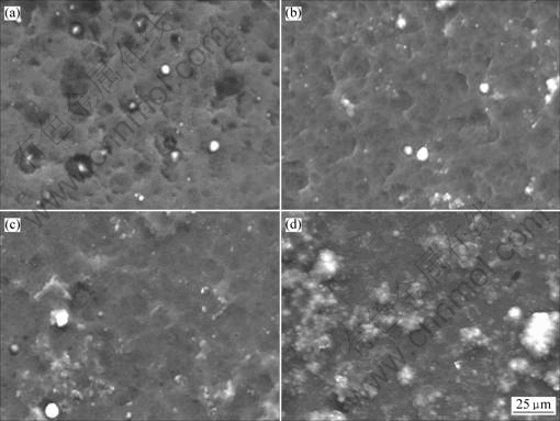
Fig.2 Surface morphologies of (Cr1-xAlx)N coatings with different Al contents: (a) x=0.12; (b) x=0.35; (c) x=0.50; (d) x=0.74

Fig.3 XRD patterns of (Cr1-xAlx)N coatings
3.2 Effects of substrate negative bias
Fig.4 illustrates the deposition rates as a function of negative pulse bias. The deposition rate constantly decreases with increasing negative pulse bias voltage. The growth rate of (Cr,Al)N coating changes from 107 to

Fig.4 Deposition rate versus substrate negative bias
72 nm/min as the negative bias increases from 0 V to 1 050 V. The change of deposition rate with increasing substrate bias of (Cr,Al)N in this work is different from that of (Ti,Al)N in our previous study[16]. In that work, TiAl alloy target was applied and the deposition rate of (Ti,Al)N initially increased and then decreased with increasing pulse bias voltage. The change of growth rate of (Ti,Al)N is ascribed to the synergistic influence of the “direction effect” and the “bombardment effect”. The difference of changing trend of deposition rate for (Cr,Al)N is related to the use of isolated Al target. The (Cr,Al)N coatings deposited at negative bias of 0 V contain plenty of droplets and the presence of the droplets contributes to the increase of deposition rate. With increasing negative bias, the enhanced bombardment effect removes more droplets.

Fig.5 Surface morphologies of (Cr,Al)N coatings deposited at different substrate negative bias voltages: (a) 0 V; (b) 150 V; (c) 450 V; (d) 750 V
The surface morphologies of the coatings deposited under different pulse negative bias voltages are shown in Fig.5. It can be seen that the increasing negative bias improves the bombardment effect. The number and size of the droplets decrease with increasing pulse bias voltage. The coatings synthesized under negative bias above 450 V exhibit obvious ion-etched morphologies.
Fig.6 shows the XRD patterns of the deposited coatings at various pulse bias voltages. All the coatings prepared herein have B1NaCl structure. But the preferred orientation changes remarkably with increasing pulse bias voltage. The coating deposited under pulse bias voltages of 0, 150 and 300 V has a preferred orientation of (111). Under the negative bias higher than 300 V, the preferred orientation changes to (200). The XRD peaks shift to lower diffraction angles (indicating an increased lattice parameter) for the coatings deposited at negative bias above 150 V. It is reported that high negative bias produces compressive stress in the coatings[17]. The change of orientation and peak position is related to the existence of compressive stress.

Fig. 6 XRD patterns of (Cr,Al)N deposited at various substrate negative bias
4 Conclusions
1) (Cr1-xAlx)N coatings with different Al content were deposited by an arc ion plating method using isolated Cr target and Al target and the change of B1(NaCl) phase to B4(wurtzite) phase takes place when the x reaches 0.7. With increasing Al content, the density of droplets on the surface of the coatings increases and the coatings is less ion-etched.
2) Due to the bombard effect of the plasma enhanced by negative bias, the increase of pulsed negative bias gives rise to less droplet contamination, the more obvious the ion-etching effect, the lower the deposition rate, the change of preferred orientation and the shift of XRD peaks.
References
[1] Schulz A, Stock H R, Mayr P, Staeves J, Schmoeckel D. Deposition and investigation of TiN PVD coatings on cast steel forming tools[J]. Surface and Coatings Technology, 1997, 94/95: 446-450.
[2] Kohlscheen J, Stock H R, Mayr P. Substoichiometric titanium nitride coatings as machinable surfaces in ultraprecision cutting [J]. Surface and Coatings Technology, 1999, 120/121: 740-745.
[3] Peng Zhi-jian, Miao He-zhuo, Qi Long-hao, Yang Si-ze, Liu Chi-zi. Hard and wear-resistant titanium nitride coatings for cemented carbide cutting tools by pulsed high energy density plasma[J]. Acta Materialia, 2003, 51: 3085-3094.
[4] IM?NEZ H, RESTREPO E, DEVIA A. Effect of the substrate temperature in ZrN coatings grown by the pulsed arc technique studied by XRD[J]. Surface and Coatings Technology, 2006, 201(3/4): 1594-1601.
[5] PERRY A J, GR?SSL M, HAMMER B. Some characteristics of HfN coatings on cemented carbide substrates[J]. Thin Solid Films,1985, 129(3/4): 263-279.
[6] SARIOGLU C. The effect of anisotropy on residual stress values and modification of Serruys approach to residual stress calculations for coatings such as TiN, ZrN and HfN[J]. Surface and Coatings Technology,2006, 20(3/4): 707-717.
[7] FATEH N, FONTALVO G A, GASSNER G, MITTERER C. Influence of high-temperature oxide formation on the tribological behaviour of TiN and VN coatings[J]. Wear,2007, 262(9/11): 1152-1158.
[8] ZHITOMIRSKY V N. Structure and properties of cathodic vacuum arc deposited NbN and NbN-based multi-component and multi-layer coatings[J]. Surface and Coatings Technology,2007, 201(13): 6122-6130.
[9] HOY R, KAMMINGA J D, JANSSEN G C A M. Scratch resistance of CrN coatings on nitrided steel[J]. Surface and Coatings Technology,2006, 200(12/13): 3856-3860.
[10] K?NIG U. Deposition and properties of multicomponent hard coatings[J]. Surface and Coatings Technology,1987, 33: 91-103.
[11] UCHIDA Hitoshi, YAMASHITA Masato, HANAKI Satoshi. UETA Takeaki. Characterization of (Ti, Al)N films prepared by ion mixing and vapor deposition[J]. Materials Science and Engineering A, 2004, 387-389: 758-762.
[12] ROMERO J, G?MEZ M A, ESTEVE J, MONTAL? F, CARRERAS L, GRIFOL M, LOUSA A. CrAlN coatings deposited by cathodic arc evaporation at different substrate bias[J]. Thin Solid Films,2006: 515(1): 113-117.
[13] KHRAIS S K, LIN Y J. Wear mechanisms and tool performance of TiAlN PVD coated inserts during machining of AISI 4140 steel[J]. Wear,2007, 262(1/2): 64-69.
[14] MAKINO Y. Prediction of phase change in pseudobinary transition metal aluminum nitrides by band parameters method[J]. Surface and Coatings Technology,2005, 193(1/3): 185-191.
[15] IKEDA T, SATOH H. Phase formation and characterization of hard coatings in the Ti-Al-N system prepared by the cathodic arc ion plating method[J]. Thin Solid Films, 1991, 195: 99-110.
[16] OLBRICH W, KAMPSCHULTE G. Additional ion bombardment in PVD processes generated by a superimposed pulse bias voltage[J]. Surface and Coatings Technology,1993, 61: 262-267.
[17] LI Ming-sheng, WANG Fu-hui. Effects of nitrogen partial pressure and pulse bias voltage on (Ti,Al)N coatings by arc ion plating[J]. Surface and Coatings Technology,2003, 167: 197-202.
(Edited by LONG Huai-zhong)
Foundation item: Project(50401022) supported by the National Natural Science Foundation of China; Project(0650034) supported by the Natural Science Foundation of Jiangxi Province, China
Corresponding author: LI Ming-sheng; Tel: +86-791-3831266; E-mail: mshli@163.com

