J. Cent. South Univ. (2012) 19: 200-205
DOI: 10.1007/s11771-012-0992-7
Combustion and energy balance of aluminum holding furnace with bottom porous brick purging system
ZHANG Jia-qi(张家奇)1, 2, ZHOU Nai-jun(周乃君)1, ZHOU Shan-hong(周善红)3
1. School of Energy Science and Engineering, Central South University, Changsha 410083, China;
2. College of Aerospace and Material Engineering, National University of Defense Technology,Changsha 410073, China;
3. Shenyang Aluminum and Magnesium Engineering and Research Institute, Shenyang 110001, China
? Central South University Press and Springer-Verlag Berlin Heidelberg 2012
Abstract: For acquiring the details in aluminum holding furnace with bottom porous brick purging system, efforts were performed to try to find out the potential optimal operation schemes. By adopting transient analysis scheme and constant boundary temperature, combustion in the furnace was investigated numerically using computational fluid dynamics (CFD). The predicted gas temperature shows good agreement with the measured results, and the predicted energy distribution of the furnace is consistent with that obtained from energy balance experiment, which confirms the reliability of the numerical solution. The results show that as the fuel-air mixture temperature rises up from 300 K to 500 K, the energy utilization of the furnace could increase from 34.55% to 37.14%. However, as the excess air coefficient increases from 1.0 to 1.4, energy utilization drops from 34.55% to 29.56%. Increasing the combustion temperature is the most effective way to improve the energy efficiency of the furnace. High reactant temperature and medium excess air coefficient are recommended for high operation performance, and keeping the furnace jamb sealed well for avoiding leakage has to be emphasized.
Key words: aluminum holding furnace; combustion; flow; numerical study; computational fluid dynamics
1 Introduction
Aluminum holding furnace, a key equipment in casting house, is used to store molten aluminum for purification and alloying processing. Well recognized criteria for evaluating the performances of holding furnace involve high product quality, minimized metal loss and energy loss [1-2]. Porous brick gas purging system, which produces finer bubbles and helps to reduce energy loss [3-4], is being applied more and more widely in aluminum holding furnace.
Linear mathematical models were used to simulate the performances of the furnace [5-6] and control the system [7-8]. In addition, there were a large amount of numerical investigations on the combustion of aluminum casting furnace [9-10]. However, they only focused on the melting furnace which has different heat transfer mechanism from that of holding furnace [2]. With the rapid increase of aluminum alloy demand, aluminum alloy technology, especially the alloying equipment holding furnace, is confronting a big challenge or opportunity, involving product quality and productive cost. This requires detailed knowledge about the operation parameters, combustion performance and energy distribution. However, it is significant for the designer or operator to know the details in furnace. As far as our best knowledge, there were no much comprehensive investigations interpreting the fluid flow and thermal field in holding furnace with porous brick purging system. Thus, the motive of the present work is to investigate the characteristics of the flow field, heat transfer, as well as the energy distribution in aluminum holding furnace, trying to find out the potential optimal operation scheme for the equipment.
In holding furnace, heat transfer is radiation dominated [2], thus reliable radiation calculation has to be included into the numerical study [11-12]. The complexity of radiation determines that the control model [5-9] approach cannot give enough accurate solution as expectation.
A number of investigations using computational fluid dynamics (CFD) method were put forward to simulate the combustion in industrial furnace [9-14], where various radiation models were used and approved, such as ZONE [9], discrete transfer radiation model (DTRM) [10] and P1 [13].
In the present work, CFD method was used to investigate the flow and thermal fields for a 50 t holding furnace. Afterwards, the effects of operating parameters on the furnace performances were discussed to find the optimal operation approach.
2 Experimental
Heat balance of a 50 t aluminum holding furnace operating on reference operation condition (ROC) was investigated experimentally. Here, a brief introduction of the experimental study was given.
The furnace body was treated as the objective during heat balance test. Throughout the whole operation period, i.e., from aluminum feeding to product pouring, parameters including temperature of combustion chamber, melt temperature, temperatures of the furnace outer walls, exhaust temperature and gas flow rate in the duct were measured and recorded continuously. In addition, fuel-air mixture flow rate and duration of heating processing were recorded as well. Based on these data, heat balance calculation can be performed according to the relevant national standard [15].
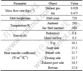
In the present work, two sets of calculation methods were adopted, where furnace body and combustion chamber were considered as “energy equipments”. Accordingly, details of the energy flow of the furnace body were estimated, by which primary operation parameters for the furnace can be obtained as Table 1 gives.
Table 1 Primary parameters in holding furnace (ROC)
3 Computational models
3.1 Geometrical model
Geometrical model of the furnace is schematically illustrated in Fig. 1. It is necessary to note that the original point of the coordinate system is exactly the intersection of furnace bottom and the expansion of line AB as Fig. 1 shows. Considering the motive of the present work, physical model (3D) that only involves the combustion chamber was built up as Fig. 2 shows. The present model is composed of 436 648 cells and 642 005 nodes.
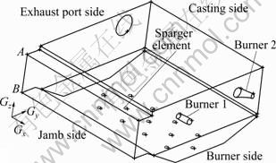
Fig. 1 Schematic overview of geometrical model of furnace
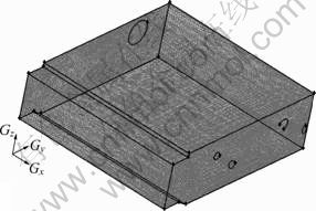
Fig. 2 Cell model of combustion chamber
3.2 Mathematical model
The conservation equations are given as
 (1)
(1)
 (2)
(2)

 (3)
(3)
 (4)
(4)
 (5)
(5)

 (6)
(6)
where ρ is the density, kg/m3; u is the velocity vector, m/s; t is the time, s; P is the pressure, Pa; g is the gravity
acceleration, 9.8 kg/s2;
 is the effective stress tensor; μ is the viscosity, kg/(m・s); μt is the turbulent viscosity, μt=cμ・ρ・κ2・ε-1 in the present turbulent model; cμ is the empirical constant, 0.09; I is the unit tensor; h is the enthalpy, J/m3; keff is the effective thermal conductivity, keff=k+kt, W/(m・K); k is the laminar heat conductivity; kt is the turbulent heat conductivity, kt=cp・μt・Prt-1; cp is the specific heat of flow, J/(kg・K); Prt is the empirical turbulent Prandtl number, 0.5; T is the temperature, K; hi is the enthalpy of species i, J/m3; Ji is the diffusion rate of species i, kg/(m・s);
  is the energy source term; mi is the mass fraction of species i; Di is the diffusion coefficient of species i in the mixture, m2/s; Sct is the turbulent Schmidt number, 0.5; Ri is the volumetric rate of creation of species i; κ is the turbulent kinetic energy, m2/s2; ε is the turbulent kinetic energy dissipation rate, m2/s3;
  is the turbulent kinetic energy generation; other turbulent model constants are listed below: σκ=1.0; σε=1.3; Cε1=1.44; Cε2=1.92. Equations (1)-(4) are the conservation equations describing continuity, momentum, energy, and species, respectively, and standard κ-ε model was adopted to simulate the turbulence viscosity as shown in Eqs. (5)-(6).
In Eq. (3), h is the sum of the enthalpies for each species hi weighted by its mass fraction mi as

 (7)
(7)
where Tref,i is the reference temperature of species i, K. is composed of chemical reactions enthalpy Sreac and radiation heat transfer Srad. The first term:
 (8)
(8)
and the second term will be calculated by P1 radiation model as Eq. (9) shows:
 (9)
(9)
where a is the fluid absorption coefficient, 0.1; Gr is the incident radiation energy, J; σ is the Stefan-Boltzmann constant, 5.67×10⁻⁸ kg/(m2・K4).
In addition, methane-air one step reaction model was applied and eddy-dissipation model was adopted to simulate chemistry-turbulent interaction.
3.3 Boundary conditions
Superficial velocities for Burner 1 and 2 were set to be 5.90 and 5.28 m/s, respectively. These values were obtained according to relevant mass flow rates of air- fuel mixture. Boundary turbulent parameters are given by κ=0.5・χuin2 and ε=2.5・cμ0.75・κ1.5・lin-1, where χ is the inlet turbulence intensity and lin is the inlet diameter, m.
Exhaust port was set to be pressure outlet with a gauge pressure of -11 Pa, which was chosen according to the measurement. On the inner walls surrounding the combustion space, non-slip momentum condition was enforced. Actual walls here were represented by “shell model” supplied by FLUENT 6.3, and heat transfer between the outer sides of the “shells” and the ambient was designated to be convection, and the heat transfer coefficients are listed in Table 1.
In most of the previous studies, steady-state solutions were performed, where combustion/melt interface was used to be set to the constant temperature boundary (consistent to melt temperature, around 1 000 K) [10-13]. However, in this way, solution would not cease until the static heat balance has been obtained in the furnace, i.e., heat generation equals the heat loss. The problem is that, actually, in the holding furnace, the energy incomes and energy expenses cannot be balanced until the melt gets to a very high temperature (e.g. 1 300 K), which deviates from the melt temperature dramatically. Therefore, new calculation approach has to be carried out for performing more accurate prediction.
In the present work, constant temperature and non-slip boundary condition were specified on the combustion/melt interface. The most important innovation is that transient solution scheme is adopted here. Thus, the corresponding results can represent the instantaneous situation, which is consistent to actual condition.
3.4 Initial condition and calculation approach
Fluid in computational domain was initialized as homogeneous temperature of 960 K and 0-velocity to perform unsteady solution. Initial mass concentration of species may be listed as: O2, 23%, N2, 77%, i.e., initially, there is no other species in the combustion chamber. Other initial conditions include: pressure P=101 325 Pa, turbulent kinetic energy κ and its dissipation rate ε are both very small values.
By setting a short period (e.g. 10 s) as the time step, the solution would not cease until the combustion gets stable, i.e. the temperature field and boundary heat flux (including top, bottom and side) do not change with time anymore. In practice, solutions demonstrate that combustion in the chamber may not be well developed if a short calculation period is selected. On the contrary, if the total calculation period is too long, the calculation may deviate from the actual condition to reduce the accuracy. Empirically, the total calculation period would be preferred in a range from 20 to 30 min. For excluding the influences of initial temperature on the results, 1 100 and 1 200 K were both adopted as the initial temperature to perform independent solution, and the same conclusion was obtained.
4 Results on ROC
On the reference operating condition (ROC), velocity and thermal fields in combustion chamber are illustrated, as shown in Fig. 3 and Fig. 4, respectively. Apparently, two streams of gas from two burners separately flow downward and toward the middle line of the chamber, causing the exhaust port localizes much closer to Burner 2, gas from Burner 1 flows as circularity-shape orbit then leaves the chamber and most gas from Burner 2 just exits the chamber from the exhaust port without too much circulation. Flame from Burner 1 is longer, because the superficial velocity of gas here is higher. Moreover, the lowest temperature zone locates on the jamb side and the highest temperature zone locates on the flame center near Burner 2.
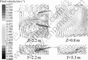
Fig. 3 Fluid velocity vector in combustion zone
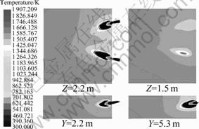
Fig. 4 Temperature distribution in combustion zone
Figure 5 shows the combustion/melt interfacial heat flux details. Obviously, the zone with the maximum heat flux locates under Burner 2, which probably attributes to the shorter flame and higher temperature here. Comparing Fig. 5(a) with Fig. 5(b), it shows that in accordance with the design principle of holding furnace [2], most of the heat flux across the interface is caused by radiation.
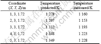
For evaluating the reliability of the numerical solution, the temperatures on the consistent points in accordance with the measurement were extracted and listed in the second column of Table 2. Comparison demonstrates that the predicted temperatures are about 10% higher than the measured values. This phenomenon is attributed to the air leakage, as the furnace jamb has to be kept open for a long period (>10 min) for measurement. This implies that the actual temperatures on these points in the sealed combustion chamber should be close to the predicted values.
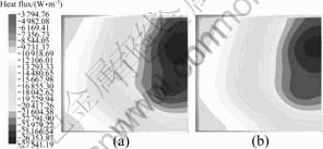
Fig. 5 Combustion-melt interfacial heat flux profile on ROC: (a) Total heat flux; (b) Radiation heat flux
Table 2 Comparison of predicted and measured temperature on representative points
In addition, the third column in Table 3 lists the predicted energy balance on ROC, which shows good agreement with the second column, heat balance from measurement and analysis. All above results demonstrate that the reliability of numerical solution is acceptable.
5 Influence factors and discussion
5.1 Fuel-air mixture temperature
As well known, preheating the reactants is a widely recognized method to improve the energy utilization for combustion. Table 3 gives the effects of reactants temperature on the combustion parameters and the energy distribution of the holding furnace. Apparently, with the increase of fuel-air mixture temperature from 300 to 500 K, combustion temperature increases and the enthalpy for preheating reactants decreases. As a result, more energy flows into the melt across surface and the effective energy ratio increases from 34.55% to 37.14% as Fig. 6 shows. Apparently, in a temperature range of 300-500 K, energy efficiency increases near linearly with the increase of reactants temperature.
5.2 Excess air coefficient
Excess air coefficient is defined as the air amount in the fuel-air mixture times the air amount theoretically required for complete oxidation. The effect of excess air on the combustion parameters can be shown in the 6th and 7th columns in Table 3. Obviously, with the increase of excess air coefficient from 1.0 to 1.2 and 1.4, combustion temperature decreases, less energy flows into the melt and effective energy ratio decreases from 34.55% to 33.21% and 29.56%.
Table 3 Heat distribution on different condition as well as from integrated thermal analysis
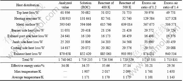
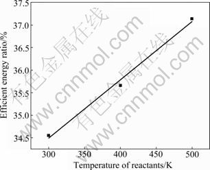
Fig. 6 Relationship between temperature of reactants and energy efficiency
5.3 Discussion
From Table 3, it is evident that as the variation of operating conditions, conduction heat loss and exhaust heat loss of the furnace do not vary much. However, the maximum temperature in the chamber, heat flow across metal surface and effective energy ratio are sensitive according to the variation of operating conditions. Obviously, the maximum combustion temperature decreases with the decrease of reactant temperature and the increase of excess air coefficient. Thus, correspondingly, heat transfers into the metal and effective energy ratio of the furnace decreases according to the principle of radiation heat transfer, which is the primary heat transfer mechanism in aluminum holding furnace.
Therefore, increasing combustion temperature probably is the most effective approach to enhance the energy utilization of the furnace. Actually, it is not practical to improve the furnace performances through restructuring furnace configuration. However, in the current stage, this objective can be probably achieved through the optimization of parameters, primarily reactant temperature and excess air coefficient.
Table 3 shows a 1.29% increase of effective energy ratio for every 100 K increase of reactant temperature and a 2.50% decrease of effective energy ratio for every 0.2 increase of excess air coefficient. This may imply that both of these two factors have to be emphasized. However, their positive effects could not be over- evaluated. The temperature of preheated reactants is restricted by economical and technological aspects, thus reactants heating has to be consistent to the existing conditions. Moreover, insufficient reaction may occur in low air-to-fuel ratio, thus an excess air coefficient of around 1.05 is recommended. Furthermore, in practice, keeping the jamb sealed well is effective and feasible to reduce unnecessary energy loss.
6 Conclusions
1) New solution more close to the actual situation is adopted and numerical results show good agreement with experimental results.
2) On ROC, the effective energy ratio is 34.55%. With the increase of fuel-air mixture temperature from 300 to 500 K, the effective energy ratio increases from 34.55% to 37.14%. With the increase of excess air coefficient from 1.0 to 1.4, effective energy ratio decreases from 34.55 % to 29.56%.
3) Preheating fuel-air mixture and reducing the excess air coefficient are the primary ways to enhance the combustion temperature, which may be the most effective methods to improve energy utilization. However, mixture preheating has to be consistent to the existing conditions and an excess air coefficient of around 1.05 is recommended.
References
[1] PRILLHOFER B, Antrekowitsch H, Bottcher H. Optimisation of the melt quality in casting/holding furnaces [C]// Deyound D H. Light Metals 2008. Warrendale: TMS, 2008: 627-632.
[2] Migchielsin I J, Hans-Walter-Grab D I, Schmidt T. Design considerations for holding and casting furnaces [C]// Deyound D H. Light Metals 2008. Warrendale: TMS, 2008: 593-596.
[3] Gamweger K, Bauer P. Energy savings and productivity increases at an aluminum slug plant due to bottom gas purging [C]// Neelameggham N R, Reddy R G., Belt C K, Vidal E E. Energy Technology Perspectives. Warrendale: TMS, 2009: 169-171.
[4] Larsen D A. Degassing aluminum using static fine-pore refractory diffusers [J]. JOM, 2007, 49(8): 27-28.
[5] Bui R T, Perron J. Performance analysis of the aluminum casting furnace [J]. Metall Trans B, 1987, 19(2): 171-180.
[6] Outllet R, Bui R T, Perron J. Numerical simulation of a casting furnace [J]. Simulation, 1990, 54(2): 92-100.
[7] Bui R T, Perron J. Optimal control of an aluminum casting furnace: Part I. The control model [J]. Metall Trans B, 1990, 21(3): 487-494.
[8] Bui R T, Perron J. Optimal control of an aluminum casting furnace: Part II. Fuel optimization [J]. Metall Trans B, 1990, 21(3): 495-500.
[9] Bourgeois T, BuI R T, Charette A, Kocaefe Y S. Mathematical modeling of an aluminum casting furnace combustion chamber [J]. Metall Trans B, 1989, 20(3): 421-429.
[10] Nieckele A O, Naccache M F, Gomes M S P. Numerical modeling of an industrial aluminum melting furnace [J]. J Energy Resour Technol, 2004, 126(1): 72-81.
[11] BOKE Y E, AYDIN O. Effect of the radiation surface on temperature and NOx emission in a gas fired furnace [J]. Fuel, 2009, 88(10): 1878-1884.
[12] Kontogeorgos D A, KERAMIDA E P, FOUNTI M A. Assessment of simplified thermal radiation models for engineering calculations in natural gas-fired furnace [J]. Int J Heat Mass Trans, 2007, 50(25/26): 5260-5268.
[13] ZHOU N J, ZHOU S H, ZHANG J Q, PAN Q L. Numerical simulation of aluminum holding furnace with fluid-solid coupled heat transfer [J]. Journal of Central South University of Technology, 2010, 17(6): 1389-1394.
[14] STEFANIDIS G D, MERCI B, HEYNDERICKX G J, MARIN G B. CFD simulations of steam cracking furnaces using detailed combustion mechanisms [J]. Comput Chem Eng, 2006, 30(4): 635- 649.
[15] GB/T 2587-2009, General principles for energy balance of equipment using energy [S]. (in Chinese)
(Edited by HE Yun-bin)
Foundation item: Project(2009GK2009) supported by the Science and Technology Program of Hunan Province, China
Received date: 2011-01-18; Accepted date: 2011-05-23
Corresponding author: ZHOU Nai-jun, Professor, PhD; Tel: +86-13973160806; E-mail: njzhou@mail.csu.edu.cn

