
Forming mechanism of integral serrated high fins by plowing-extruding based on variational feed
WAN Zhen-ping(����ƽ), YAN Hui(�� ��), TANG Yong(�� ��)
School of Mechanical and Automotive Engineering, South China University of Technology,Guangzhou 510640, China
Received 6 February 2009; accepted 26 May 2009
Abstract: Plowing-extruding tool was designed and plowing-extruding process was investigated. Then, a manufacturing method of integral serrated high-finned tube, plowing-extruding based on variational feed was proposed, in which plowing-extruding tool moved forward at two different feeds, f1 and f2, in turn. In this method, overlaps that are usually avoided in practical application were utilized to manufacture high fins and average height of fins was up to 1.58 mm. The critical feed (fc) of overlaps forming and terms of high fins forming were analyzed. The main technical parameters that affect the fins height were discussed. The experimental results show that the fins height increases with extruding inclination angle and plowing-extruding depth, and the fins height increases with f1 increasing when f1 is smaller than fc, and decreases with f1 increasing if f1 is larger than fc.
Key words: enhanced heat transfer tube; integral serrated high fins; plowing-extruding
1 Introduction
Shell-and-tube heat exchangers are widely used in various applications such as power generation, petroleum refining, and chemicals. The heat transfer tube is the key component of shell-and-tube heat exchanger. According to BERGLES�� viewpoint[1], bare tube, plain or two-dimensional fins and three-dimensional or serrated tubes are the first, second and third generation of heat transfer technology, respectively. BERGLES[1] also pointed out that the second generation of heat transfer technology had been well established, and what we wanted now was the third[2] and the fourth[3] generation heat transfer technology. Therefore, investigation and development on serrated tubes have been the subject of advanced enhancement of heat transfer. By and large, serrated tubes can be put into two categories: one is welding finned tube and the other is integral finned tube. Welding finned tubes include Sunrod pin-fin tube[4], pin fin tube[5-6]; integral finned tubes cover integral pin-tube[7], petal-shaped finned tube[8-9], three-dimensional rib-finned tube[10], etc. In consideration of thermal contact resistance and material saving, integral finned tube is more advantageous than welding finned tube. Petal-shaped finned tube has been applied widely due to its high efficiency of heat transfer and small pressure drop[11]. However, petal-shaped finned tube is a kind of low-finned tube. If viscosity of fluid is large, the low fins of the tube will not work. Therefore, investigations into integral serrated tube with high fins have attracted more and more interest.
Up to now, there are three main methods to manufacture integral finned tube. They are cutting-press[12], chopping-extrusion[13] and pre-roll ploughing[14-16]. Cutting-press and chopping-extrusion can only produce integral plain finned tube. Pre-roll ploughing can manufacture integral serrated finned tube, namely petal-shaped finned tube. But, the fins height of petal-shaped finned tube is very low.
In this work, a manufacturing method of integral serrated high-finned tube, plowing-extruding based on variational feed, is proposed. The plowing-extruding tool plows into and extrudes surface metal of workpiece at two different feeds in turn. By this new method, higher fins than those of petal-shaped finned tube can be machined out with high efficiency. The forming mechanism of integral serrated high fins by plowing-extruding based on variational feed is illustrated and the main technical parameters that affect the height of fins are discussed.
2 Process of plowing-extruding
2.1 Shape of plowing-extruding tool
Schematic map of plowing-extruding tool is shown in Fig.1.
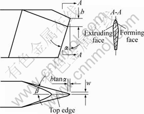
Fig.1 Schematic map of plowing-extruding tool
In Fig. 1, �� is extruding inclination angle, �� is clearance angle, w is a half of maximal land width of extruding flank and b is the pitch between tool tip and position of maximal land width of extruding flank. The plowing-extruding tool has no cutting edge and is composed of two curved faces named as extruding face and forming face with conterminous curve named as top edge. The cross section of the tool is like a wedge as shown in section A-A in Fig.1.
2.2 Process of plowing-extruding
Bevel ribs with triangular cross section are machined out on the outside surface of bare tube by rolling before plowing-extruding experiments are conducted.
The plowing-extruding tool can plow into workpiece but does not remove surface metal. The surface metal at the vicinity of workpiece and top edge is split into two parts, where plastic deformation occurs due to actions of extruding and forming face. Lumps form due to the action of extruding face when the special tool plows into workpiece. With tool feed movement (f), the top edge may be beyond, just on or on the right of the lumps in the next turn. If the top edge is just beyond the lumps, as illustrated in Fig.2(a), the top edge would separate the lumps from surface metal in the left vicinity of top edge, and at the same time, the forming face extrudes the lumps into serrated fins, as shown in Fig.3(a). If the top edge is just on the lumps, the top edge would split the lumps into two pieces and parts of lumps are removed. As a result, remaining lumps are extruded into fragmentary fins shown in Fig.3(b). If the top edge is on the right of the lumps, as illustrated in Fig.2(b), the lumps are extruded continually into overlaps (as shown in Fig.3(c)) by extruding face. From above analysis, feed is the crucial factor on fins forming by plowing- extruding.
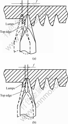
Fig.2 Process of plowing-extruding: (a) Top edge beyond lumps in next turn; (b) Top edge on right of lumps in next turn
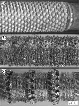
Fig.3 Photographs of finned tube machined by plowing-extruding with different feeds: (a) Integral serrated low fins; (b) Fragmentary fins; (c) Overlaps
3 Mechanism on integral serrated high fins forming
3.1 Proposing of plowing-extruding method based on variational feed
The fins height of the integral serrated finned tube shown in Fig.3(a) is only about 0.3-0.7 mm, where the height of fin is defined as a half of remaining amount after outside diameter of finned tube is subtracted from outside diameter of base tube. This kind of tube is regarded as low-finned tube. The finned tube shown in Figs.3(b) and (c) cannot meet the needs of practical application and should be usually avoided in the process of plowing-extruding. However, the overlaps shown in Fig.3(c) can be utilized to manufacture high fins. The method is that the overlaps are extruded into high fins by forming face when the top edge of tool is just beyond the overlaps in the next turn once overlaps form. The height of fins made of overlaps is higher than that of fins shown in Fig.3(a) since the height of overlaps is larger than that of lumps.
3.2 Term of overlap forming
From forementioned analysis, the premise of high fins forming by plowing-extruding based on variational feed is overlap forming. In the term of overlap forming, the top edge is on the right of the lumps in the next turn once lumps form. Fig.4 shows the zoom drawing of plowing-extruding zone.
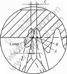
Fig.4 Terms of overlap forming
The critical feed (fc) of overlap forming is
fc = lAB+c (1)
where lAB is axial projection distance when intersectant curve between outside surface of workpiece and extruding face of tool is projected on tool reference plane; and c is an adjunctive constant, whose value is 0.1-0.15 mm decided by experiments.
From Fig.1, lAB can be inferred as
lAB=w+(ap-btan��)tan�� (2)
where ap is plowing-extruding depth.
Combining Eqs.(1) and (2), fc can be deduced as
fc=w+(ap-btan��)tan��+c (3)
So, the term of overlap forming is
f��w+(ap-btan��)tan��+c (4)
3.3 Process of high fins forming
The mechanism on integral serrated high fins forming by plowing-extruding based on variational feed is illustrated in Fig.5.
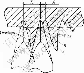
Fig.5 Mechanism of serrated high fins forming by plowing-extruding based on variational feed
In Fig.5, lumps are extruded into overlaps if feed f1 is smaller than fc. Once overlaps form, the feed f1 is shifted to feed f2 to ensure that the top edge is just beyond the overlaps in the next turn so that the overlaps are extruded into high fins by forming face. So, during high fins forming by plowing-extruding, the tool moves forward with feed f1 and feed f2 in turn. From Fig.5, f2 is calculated from the following formula:
f2=2lAB+hD=2[w+(ap-btan��)tan��]+hD
where hD is the thickness of overlaps.
4 Experimental results
4.1 Experimental setup
Straight ribs with triangular cross section were machined out on the outside surface of base tube by rolling before experiments.
Dry plowing-extruding experiments were conducted on the precise numerical control lathe NS-20. Red copper TP2 was used as workpiece with outside diameter of 12.6 mm and wall thickness of 1.25 mm. High speed steel tool with maximal land width of extruding flank of 0.5 mm was used to machine workpiece at plowing- extruding speed of 4 m/min and plowing-extruding depth of 1.1 mm. The tool parameters ��, b and �� were 22?, 1.5 mm and 8?, respectively.
4.2 Photograph of high fins
Fig.6 shows the photograph of integral serrated fins machined by plowing-extruding at feed of 0.6 mm/r and 1.7 mm/r in turn. The average height of fins is up to 1.26 mm that is far beyond the height of fins machined by pre-roll ploughing. So, this kind of integral serrated fin is regarded as high fin. The manufacturing method of integral serrated high fins is highly efficient and inexpensive, and can be transferred to mass production.
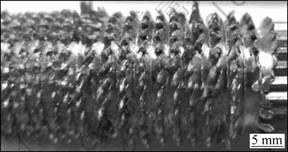
Fig.6 Photograph of high fins machined by plowing-extruding (f1=0.6 mm/r, f2=1.7 mm/r)
4.3 Influence of technical parameters on height of fins
In the process of integral serrated high fins forming by plowing-extruding based on variational feed, the technical parameters including extruding inclination angle ��, feed f1 and plowing-extruding depth ap have important influence on height of fins.
4.3.1 Influence of extruding inclination angle on height of fins
The influence of extruding inclination angle �� on fins height h is shown in Fig.7. From Fig.7, the fins height is up to 1.58 mm that is far beyond the fins height shown in Fig.3(a). It is suggested by experiments that �� should be within the range of 16?-28? since fragmental chips would be produced if �� is beyond 28?, and fins height would be low if �� is very small.
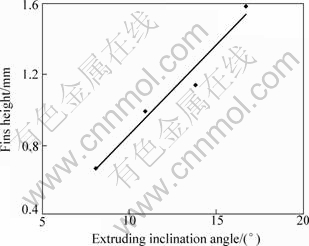
Fig.7 Influence of extruding inclination angle �� on fins height
4.3.2 Influence of feed f1 on height of fins
Fig.8 shows the influence of feed f1 on fins height. From Fig.8, the fins height is 0.84-1.25 mm and beyond the height of fins machined by pre-roll ploughing. In addition, the fins height increases with f1 increasing when f1 is smaller than 0.8 mm/r, and decreases with f1 increasing if f1 is larger than 0.8 mm/r. The reason is that fc is 0.77 mm/r from Eq.(3) and overlaps cannot form when f1 is larger than 0.8 mm/r.
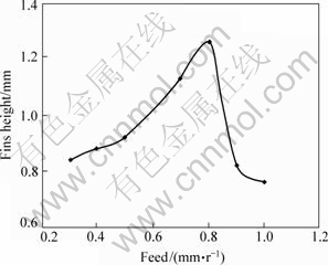
Fig.8 Influence of feed f1 on fins height
4.3.3 Influence of plowing-extruding depth on height of fins
Fig.9 presents the influence of plowing-extruding depth ap on fins height. As shown in Fig.9, the fins height increases with ap increasing. But, the value of ap cannot be too large because the wall thickness between fins root and inner surface of tube would be very small if ap is too large. Too small wall thickness is detrimental to performance of heat transfer tube because it bears a certain pressure in operation.
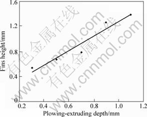
Fig.9 Influence of plowing-extruding depth ap on fins height
5 Conclusions
1) In the process of plowing-extruding, three kinds of fins, named as integral serrated low fins, fragmentary fins and overlaps, are produced at different feeds. Fragmentary fins and overlaps should be usually avoided since they cannot meet the needs of practical applications.
2) Plowing-extruding at two different feeds, f1 and f2, is an effective manufacturing method of enhanced heat transfer tube with integral serrated high fins. The forming mechanism of integral serrated high fins is that overlaps are utilized and extruded into high fins. The critical feed of overlaps forming and the terms of high fins forming are inferred.
3) The fins height increases with the increase of extruding inclination angle and plowing-extruding depth, and increases with f1 increasing when f1 is smaller than fc, and decreases with f1 increasing if f1 is larger than fc.
References
[1] BERGLES A E. Enhanced heat transfer: Endless frontier, or mature and routine [J]. Journal of Enhanced Heat Transfer, 1999, 6(2/4): 79-88.
[2] BERGLES A E. Advanced enhancement��Third generation heat transfer technology, or the ��Final Frontier�� [J]. Transaction of the Institute of Chemistry Engineering (Part A), 2001, 79: 437-444.
[3] BERGLES A E. ExHFT for fourth generation heat transfer technology [J]. Experimental Thermal and Fluid Science, 2002, 26(2/4): 335-344.
[4] FANG Jiang-min, MA Xiao-ming, LI Hua, QIAN Song-wen. Study on heat transfer enhancement performance and optimization of Sunrod pin-fin tube [J]. Petro-chemical Equipment, 2002, 31(4): 10-13. (in Chinese)
[5] SAHITI N, DURST F, DEWAN A. Heat transfer enhancement by pin elements [J]. International Journal of Heat and Mass Transfer, 2005, 48(23/24): 4738-4747.
[6] YAKUT K, ALEMDAROGLU N, SAHIN B, CELIK C. Optimum design-parameters of a heat exchanger having hexagonal fins [J]. Applied Energy, 2006, 83(2): 82-98.
[7] QIAN Song-wen , MA Xiao-ming, FANG Jiang-min, YANG Li-ming. Research and comparison of heat transfer and pressure drop of integral pin-fin tubes [J]. Journal of Chemical Industry and Engineering (China), 2002, 53(7): 700-704. (in Chinese)
[8] GAO Xue-nong, HUANG Yu-you, CHEN Shu. Heat transfer and fluid flow performance of air flowing through the helical channel outside a vertical petal-shaped fin tube [J]. Journal of Chemical Engineering of Chinese Universities, 2006, 20(4): 653-656. (in Chinese)
[9] ZHANG Z G, YU Z S, FANG X M. An experimental heat transfer study for helically flowing outside petal-shaped finned tubes with different geometrical parameters [J]. Applied Thermal Engineering, 2007, 27(1): 268-272.
[10] WANG Zhen-yong, ZHANG Zhen-guo, FANG Xiao-ming. Study on heat transfer enhancement of a helically baffled heat exchanger combined with three-dimensional rib-finned tubes [J]. Chemical Engineering & Equipment, 2008(5): 44-48. (in Chinese)
[11] ZHANG Z G, FANG X M. Comparison of heat transfer and pressure drop for the helically baffled heat exchanger combined with three-dimensional and two-dimensional finned tubes [J]. Heat Transfer Engineering, 2006, 27(7): 17-22.
[12] YUAN Qi-long, LI Yan, XIAO Ji-ming, ZHU Jiang-xin, LI Peng-yang. Cutting-press compound shaping technique [J]. The Chinese Journal of Nonferrous Metals, 2005, 15(6): 860-864. (in Chinese)
[13] XIA Wei, WU Bin, TANG Yong, YE Bang-yan. On chopping�Cextrusion of integral-fin copper tubes [J]. Journal of Materials Processing Technology, 2003, 138(1/3): 385-389.
[14] WU Bin, XIA Wei, TANG Yong, SHI Guo-chuan. Development of new type 3D integral-fin copper tubes [J]. China Mechanical Engineering, 2002, 13(13): 1134-1136. (in Chinese)
[15] TANG Yong, XIA Wei, LIU Shu-dao, ZENG Zhi-xin, YE Bang-yan. Fin formation model during pre-roll ploughing of copper 3D outside fin tube [J]. Trans Nonferrous Met Soc China, 2001, 11(5): 712-716.
[16] TANG Yong, LU Long-sheng, PAN Min-qiang, LIU Xiao-kang, LIU Xiao-qing. Formation mechanism of external finned tubes by extrusion-plough method [J]. Trans Nonferrous Met Soc China, 2006, 16(s2): S283-S288.
Foundation item: Project(50605023) supported by the National Natural Science Foundation of China
Corresponding author: WAN Zhen-ping; Tel: +86-20-85516947; E-mail: zhpwan@scut.edu.cn
DOI: 10.1016/S1003-6326(09)60153-9
(Edited by YANG Bing)

