ИИАӯЙмИдұдіЙРОTi-6Al-4V°еІДөД№ӨТХІОКэУЕ»Ҝ
АҙФҙЖЪҝҜЈәЦР№ъУРЙ«ҪрКфС§ұЁ(УўОД°ж)2015ДкөЪ2ЖЪ
ВЫОДЧчХЯЈәРӨҫьҪЬ АЙэ АоРЎЗҝ ¶Ў ЕО ХФ ҝӯ »Жҹ@ХС РшГчҪш
ОДХВТіВлЈә420 - 428
Key wordsЈәTi-6Al-4V alloy; hot stretch-creep forming; springback; orthogonal experiment; optimization
ХӘ ТӘЈәИИАӯЙмИдұдКЗТ»ЦЦјУ№ӨіЈОВДСіЙРОұЎұЪҪрКфЕчБПөДРВјјКхЎЈІЙУГЛДТтЛШЎўИэЛ®ЖҪХэҪ»ұнЈ¬УЕ»ҜБЛИИАӯЙмИдұдTi-6Al-4V°еІДөД4ёц№ӨТХІОКэЈәОВ¶ИЎўАӯЙмЛЩВКЎўІ№АӯЙмБҝәНұЈОВКұјдЎЈХэҪ»КФСйҪб№ыұнГчЈәОВ¶ИКЗУ°Пм»ШөҜҪЗөДЧоЦШТӘТтЛШЈ»СШАӯЙм·ҪПтіЙ0Ўг·ҪПтөДұдРОІДБПЗь·юУҰБҰФцјУЈ¬СШ45ЎгәН90Ўг·ҪПтөДЗь·юУҰБҰО§ИЖОҙұдРОІДБПөДЗь·юУҰБҰРЎ·¶О§ІЁ¶ҜЎЈҫӯ№эИИАӯЙмИдұдіЙРОЈ¬ұдРОІДБПОў№ЫЧйЦҜЦРaПаУЙ¶МПёҫ§БЈұдіЙіӨПёҫ§БЈЈ¬ұдРОІДБППФОўУІ¶ИФЪіЙРОЗ°әуұд»ҜәЬРЎЎЈЧЫәП»ШөҜҪЗЎўЗь·юЗҝ¶ИЦёұкХэҪ»·ЦОцҪб№ыәНІДБПОў№ЫЧйЦҜұд»ҜЗйҝцЈ¬өГіцБЛИИАӯЙмИдұдёҙәПіЙРОөДУЕ»Ҝ№ӨТХІОКэОӘЈәОВ¶И700 ЎгCЈ¬АӯЙмЛЩВК5 mm/minЈ¬І№АӯВК2%Ј¬ұЈОВКұјд8 minЎЈ
Abstract: Hot stretch-creep forming (SCF) is a novel technique to produce hard-to-form thin-walled metal components. Comprehensively considering the analysis results of the springback angle, yield strength and microstructure, four hot SCF process parameters including temperature, stretch velocity, post stretch percentage and dwelling time of a Ti-6Al-4V alloy sheet were optimized using an orthogonal experiment. The results reveal that temperature is the most important factor on springback angle. The yield strength of the deformed material in 0Ўг direction increases, while those in directions of 45Ўг and 90Ўг fluctuate around the original value. After hot SCF, the shape of some a phases changes from short thin grains to long slender ones, and the microhardness changes very little. The optimized parameters with temperature of 700 ЎгC, stretch velocity of 5 mm/min, post stretch percentage of 2% and dwelling time of 8 min are achieved finally.
Trans. Nonferrous Met. Soc. China 25(2015) 420-428
Jun-jie XIAO1,2, Dong-sheng LI2, Xiao-qiang LI2, Pan DING2, Kai ZHAO2, Xuan-zhao HUANG2, Ming-jin XU1
1. School of Mechanical and Electrical Engineering, Beijing Institute of Graphic Communication, Beijing 102600, China;
2. School of Mechanical Engineering and Automation, Beihang University, Beijing 100191, China
Received 1 April 2014; accepted 5 August 2014
Abstract: Hot stretch-creep forming (SCF) is a novel technique to produce hard-to-form thin-walled metal components. Comprehensively considering the analysis results of the springback angle, yield strength and microstructure, four hot SCF process parameters including temperature, stretch velocity, post stretch percentage and dwelling time of a Ti-6Al-4V alloy sheet were optimized using an orthogonal experiment. The results reveal that temperature is the most important factor on springback angle. The yield strength of the deformed material in 0Ўг direction increases, while those in directions of 45Ўг and 90Ўг fluctuate around the original value. After hot SCF, the shape of some a phases changes from short thin grains to long slender ones, and the microhardness changes very little. The optimized parameters with temperature of 700 ЎгC, stretch velocity of 5 mm/min, post stretch percentage of 2% and dwelling time of 8 min are achieved finally.
Key words: Ti-6Al-4V alloy; hot stretch-creep forming; springback; orthogonal experiment; optimization
1 Introduction
Providing a series of merits of high strength, corrosion resistance and low density, Ti-6Al-4V alloy is the most commonly used alpha/beta titanium alloy and has covered over 50% of the full shares of titanium applications [1]. Even, it has accounted for approximately 80% of the total titanium used in USA [2]. But the formability of titanium is so poor that titanium alloy components cannot be formed at room temperature normally. They are often manufactured in hot environment as their formabilities are enhanced greatly and their deformation resistances decrease significantly at elevated temperature [3,4].
From 1950s, scholars began examining electricity effect on materials to achieve thermal forming. In 1959, MACHLIN [5] concluded that electricity affected flow stress, ductility and yield strength of a NaCl salts significantly. GERMAIN [6], ULLRICH [7] and VALANCE [8] introduced the benefits and drawbacks of hot working via resistance heating from two aspects of economy and energy consumption. KARUNASENA [9] indicated that the current density, environmental temperature, wind velocity, cross-sectional area and length of the sheet were key factors for the heating velocity of the electrified sheet. MAKI et al [10-14] performed a series of stamping and punching experiments for ultra high tensile strength steel sheets via resistance heating. Their research results show that the shearing area quality of the components formed with resistance heating is better than those with other approaches, and the springback of components decreases greatly. JONES et al [15] carried out a simple stretch-forming process on 304 stainless steel specimens using an electrically-assisted forming technique. On one hand, they found that the flow stress decreased due to the resistance heating. On the other hand, the formability decreased on account of non-uniform distribution of temperature among the blank body. OZTURK et al [16] investigated the formability of a Ti-6Al-4V alloy in different processing conditions. These results show that the hardness and grain size of the material do not change during the resistance heating process while the springback of the components decreases effectively. FAN et al [17] investigated the electric hot incremental forming of AZ31 and TiAl2Mn1.5 sheets and found that their formabilities were improved greatly. Some international patents also introduced that thin-walled titanium alloy components were formed via resistance heating. Among them, POLEN et al [18,19] utilized the modern control algorism to realize the resistance heating on-line and real-time control of temperature, and manufactured profile titanium alloys components. MINAKAWA et al [20,21] formed the elongated metal bars with resistance heating and die heating.
Process parameters affect the microstructure and mechanical properties of the components during a manufacturing procedure, especially during hot working. So the determination of the parameters is very important. Some methods such as the morphological matrix and the orthogonal experiment are often utilized to optimize process parameters. GUO et al [22] optimized squeeze cast process parameters of AZ80 magnesium alloy by morphological matrix. BAI et al [23] used an orthogonal experiment to study the influence of plasma-MIG welding parameters on the aluminum weld porosity and achieved optimum conditions. The dissolution behaviors of Ta2O5, Nb2O5 and their mixture in KOH and H2O system were investigated by a L9(34) orthogonal experiment [24]. Taking the thin-walled 6061-T4 Al alloy tube as the objective, LI et al [25] conducted the single-factor experimental analysis and the 3D-FE based numerical orthogonal test to investigate the effects of forming parameters on the springback behaviors in tube bending of the 6061-T4 Al alloy. WU et al [26] optimized parameters of pretreatment by an orthogonal experiment.
In this work, the novel technique of hot stretch- creep forming (SCF) via resistance heating is developed and the process parameters of a Ti-6Al-4V alloy sheet during hot SCF are optimized by an orthogonal experiment.
2 Principle of hot SCF
Resistance heating is an effective and economical method to heat the metal material to the target temperature in a few minutes, which utilizes the heat generated by electrical current in the metal, i.e., Joule heat. Resistance heating does help to decrease the springback and improve the formability of the titanium alloy sheets. Hot SCF via electric resistance heating uses the above benefits, especially the high heating speed. It is an energy saving and high efficiency method to manufacture thin-walled titanium alloy components.
Hot SCF is a novel technique to manufacture thin- walled such as sheet or profile titanium alloy components. In the process, the metal blank is heated to the target temperature via resistance heating and stretched beyond its yield strength. Then, the blank is bended to the target position over the working surface of the die, and post-stretched to the target strain. In the position over the working surface, the workpiece is maintained for a few minutes. The material creeps and the stress in the material relaxes in the same time. Thus, the component can be formed precisely.
3 Experimental
3.1 Test material
A Ti-6Al-4V alloy sheet of 1.5 mm thickness was used as the material after a hot annealing and cold rolling treatment. The specimen was fabricated and stretched in rolling direction. Figure 1 shows the initial microstructure of the specimen.

Fig. 1 Microstructure of original Ti-6Al-4V alloy sheet
3.2 Process route of hot SCF
Before performing the basic experiments to investigate the process parameters, the process technology route diagram of hot stretch-creep forming is developed according to its principle as shown in Fig. 2.
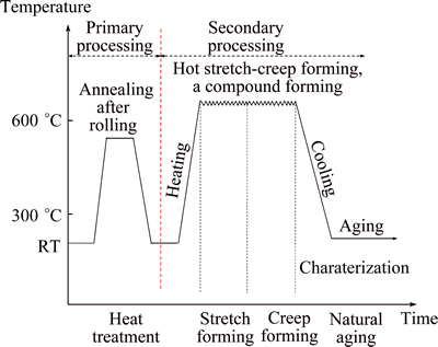
Fig. 2 Process technology route diagram of hot SCF
The component model for hot SCF process is a single curvature component with thickness of 1.5 mm and bending radius of 597 mm.
3.3 Orthogonal experiment
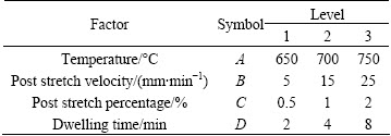
Orthogonal experiments were carried out to optimize the process parameters of the hot SCF. When choosing the orthogonal experiment, an appropriate type of orthogonal table should be decided firstly, and the factors and levels should be chosen. Here, the process parameters were optimized from the orthogonal analysis for the indicators of an orthogonal experiment type L9(34). The chosen factors and levels can be seen in Table 1.
Table 1 Experimental factors and levels
In order to produce thin-walled titanium alloy components precisely, the springback angle was chosen as an indicator to optimize process parameters. At the same time, the component must work in the security range of strength, so the yield strength was taken as another indicator for parameter optimization. In addition, from the microscopic points, the microstructure and microhardness were taken into consideration. Finally, the process parameters of hot SCF were optimized from the comprehensive analysis of the indicators.
3.4 Experimental procedure
Orthogonal experiments were carried out on the self-developed hot SCF equipment [27,28], which can be seen in Fig. 3. The radius of the compensated die surface of the tooling system is 597 mm. The die material is Ni7N (ZG35Cr24Ni7SiN), which can suffer the temperature as high as 1000 ЎгC.
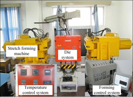
Fig. 3 Photograph of hot SCF equipment
The steps of the orthogonal experiment are as follows. Step 1, place die apparatus on the stretch forming machine, then place Kao-wool as an insulating layer within the jaws of machine and over the dieЎҜs surface to insulate the blank. Step 2, clamp the blank with copper electrodes, then transform 380 V to 3-36 V and energize the electrode and blank to produce current and heat the blank. Step 3, the heating rate of the blank maintains 5-25 K/s by adjusting the output voltage according to the measured temperature with the thermocouples in real time; the output voltage and output current are 3-36 V and 500-5000 A, respectively; generally, for safety, the electric current should be less than 1000 A and the heating time is controlled in 4 min. Step 4, when the blank temperature reaches the target one, keeping the temperature constantly, clamp and pre-stretch the blank to the target strain at a forming velocity. Step 5, when the blank reaches the straight state by pre-stretching, the workbench of stretch machine would drive the die tooling apparatus upward; over the die, the blank is shaped at target temperature until completely bending. Step 6, after the blank is fully bent, stretch the workpiece to the final strain percent against the die at the target temperature. Step 7, at the final strain position of the post stretching, hold the blank for some time at the target temperature, then, the material creeps; this would lead to the relaxation of the internal stress in the blank. Step 8, shut off the power supply to prevent electrifying the blank. Finally, remove the formed component from the machine after cooling. The whole process terminates. The components suffered from hot SCF can be seen in Fig. 4.
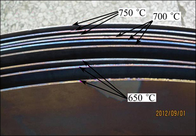
Fig. 4 Components suffered from hot SCF
4 Results and discussion
The mechanical properties of deformed materials suffered resistance heating should be as close as those at room temperature. In other words, the material properties cannot be changed obviously, and they must meet manufacturing specifications. Otherwise, this method is not appropriate to be applied. Therefore, the process parameters of the Ti-6Al-4V alloy sheet during hot SCF were optimized by analyzing experiment results from macro and micro perspectives. Herein, the macroscopic experiments include the measurement of the componentЎҜs curvature radius and the uniaxial tensile test. The microscopic experiments include the metallographic and microhardness tests. The regions A, B and C of the formed component were selected to analyze the macro experiment results, which are shown in Fig. 5.
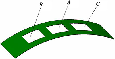
Fig. 5 Selected regions of hot SCF component
4.1 Curvature radius
The traditional measurement method of the plane skin is pressure-feeler detection, which has obvious disadvantages. Firstly, this method is based on the artificial experience to load on the component, so it is difficult to accurately control the load amount. Secondly, the measurement accuracy of the feeler gauge is also very limited. Lastly, the measured area has the uncertainty and weak rigidity, which are not conducive to measure the skin parts precisely. Therefore, the advanced non-contact digital measurement method should be used for the measurement of the aircraft skin component.
A handheld optical three-dimensional scanner typed 3D Camega PCP-1200, a non-contact digital measurement equipment, has been utilized to measure the curvature radius of the formed component. Its measurement accuracy is 0.01 mm. It caters to measure three-dimensional surfaces of complex body. The system has advantages of lightweight structure and flexible multi-directional scanning in hand. WhatЎҜs more, it has very high scanning speed. Its single scan time is less than 0.15 s. So it is the ideal choice for scanning the small or medium-sized objects. During the measurement, the MCF control system is used for the device control, the WINMOIRE is used to collect points, and the CLOUDFORM is used to deal with point clouds. By removing noise points and smoothing them, the three-dimensional surface of the formed component can be obtained and the curvature radius can be fitted.
According to the measured curvature radius and supposing the length of the neutral layer to be constant, the springback angle has been calculated. The fitting results of springback angle and analysis of the orthogonal experiment are given in Table 2.
It can be seen from Table 2 that R(A)=7.266, R(B)=0.592, R(C)=0.931 and R(D)=1.077. So the importance order of the factors is temperature, dwelling time, post stretch percentage and stretch velocity. With changes of various factors and levels, the change law of springback angle is shown in Fig. 6.
Some conclusions can be drawn from Fig. 6 as follows.
1) Temperature is the main factor affecting the springback angle. With the increase of temperature, the springback angle can be reduced significantly.
2) Dwelling time and post stretch percentage have little effect on the springback angle. The increase of dwelling time and post stretch percentage should reduce the springback, but the experimental results present that the springback angle fluctuates in a small amount. This may be caused by the instability and unevenness of the friction in experiments. Also, it may be caused by the experimental error. However, due to the fluctuations of the springback angles caused by these two factors are very little, these changes can be thought to be acceptable.
3) Stretch velocity has little effect on springback angle. It can be seen from Fig. 6 that the springback angle increases with the increase of the stretch velocity.
Table 2 Orthogonal results and analysis of springbanck angle
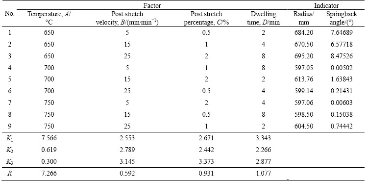
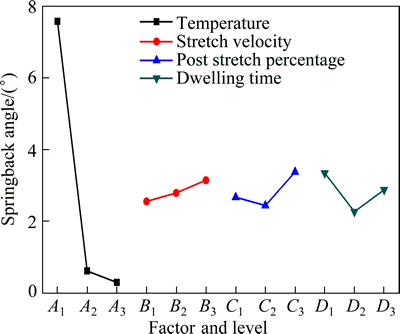
Fig. 6 Influence of factors and levels on springback angle
The differences of the indicator on the various factors in Table 2 are only caused by the levels of a certain factor, which are not affected by the changes of other levels of factors. So, the combination of the best level of each factor is the best production conditions. As can be seen from Fig. 6, the combination of A3B1C2D2 is the best condition, which can reduce the springback angle to the smallest amount. However, for titanium alloys suffered from hot SCF, forming process and mechanics state are exceptionally complex and time-depended. For example, although the stretch velocity leads to an increasing trend on the friction coefficient, the stretch velocity is not the smaller the better. The production efficiency must be considered and the stretch velocity should be chosen in a reasonable range. WhatЎҜs more, the higher temperature and longer dwelling time, the more serious the oxidation of the surface of the titanium alloy component [29]. Therefore, the process parameters of hot SCF should be neatly selected. It can be seen from Table 2 that the springback angle of formed components can be reduced significantly with dwelling time of 8 min at 700 ЎгC. So the process parameters of Ti-6Al-4V alloy sheet components suffered from hot SCF are chosen as A2B1C2D3. They are temperature of 700 ЎгC, tensile speed of 5 mm/min, post stretch percentage of 1%, and dwelling time of 8 min.
4.2 Yield strength
To investigate the effect of hot SCF process on the deformed material, the mechanical properties of the components have been checked. Along the stretching directions of 0Ўг, 45Ўг and 90Ўг, specimens for the uniaxial tensile test were taken from the formed components via laser cutting. The uniaxial tensile tests were conducted on Huayin Electronic Universal Experimental Machine according to GB/T 228ЎӘ2002.
The yield strength values of the hot SCFed components are given in Table 3.
Table 3 Yield strength of hot SCFed components (MPa)

It can be seen form Table 3 that the yield strength in 0Ўг direction of the Ti-6Al-4V alloy suffered hot SCF increases a little. The reason may be that the materialЎҜs structure has changed to some extent due to the creep in the hot environment. While in 45Ўг direction, the yield strength increases under most process conditions, and reduces a little under rest conditions. In 90Ўг direction, the yield strength reduces under most process conditions and increases a little under rest conditions.
The yield strength in 0Ўг direction along the rolling direction, which is the stretching direction, is chosen to be the indicator for orthogonal analysis herein. The results are shown in Table 4.
Table 4 shows that the range order is R(C)>R(D)> R(B)>R(A). The importance order of the factors affecting the yield strength in 0Ўг direction is post stretch percentage, dwelling time, stretch velocity and temperature. With the changes of various factors and levels, the change of yield strength in 0Ўг direction is plotted in Fig. 7.
Table 4 Orthogonal analysis of yield strength in 0Ўг direction
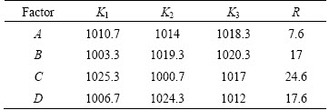
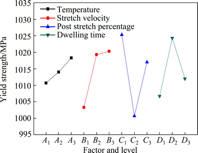
Fig. 7 Influence of factors and levels on yield strength in 0Ўг direction
It can be seen from Fig. 7 that the yield strength of the deformed material in 0Ўг direction increases with the increase of temperature and stretch velocity. This may be the result of strain hardening of the material at low and medium temperature. The yield strength of the deformed material in 0Ўг direction firstly decreases and then increases with the increase of post stretch percentage. The yield strength in 0Ўг direction firstly increases and then decreases with the increase of dwelling time. These may be related to dynamic recrystallization of the alloy at 750 ЎгC. For the deformed material, higher yield strength is the requirement of the engineering application. Based on the analysis of the indicator of yield strength in 0Ўг direction, the optimum conditions can be concluded to be A3B3C1D2.
Similarly, selecting the yield strength of the deformed material in 45Ўг direction along the rolling direction as the indicator for the orthogonal analysis, the optimum conditions are A1B3C3D2. Selecting the yield strength of the deformed material in 90Ўг direction along the stretch direction as the indicator for the orthogonal analysis, the optimum conditions are A2B2C3D2.
In fact, the optimization of process parameters should be determined by considering the yield strength in three directions above comprehensively. As the actual processing conditions influence the material properties, the sheet surface oxidation, processing efficiency, the clamp force, forming force, etc., the processing parameters are neatly chosen to be A2B2C3D2.
4.3 Microstructure
To characterize the a and b phase size and morphology quantitatively in the region A as in Fig. 5, the microstructure of the deformed Ti-6Al-4V alloy suffered from coupling fields of the electrical and load along the stretch direction were observed by optical microscope. Figure 8 shows that a small amount of b phases lie in the intergranular position of the a phase grains [30,31].
Figure 8 shows the change of a and b phases under the orthogonal experimental conditions. The shape of some a phases changes from short thin grains to long slender ones, and the grain length may be multiple times that of the original. It is obvious that some a phases and b phases begin to form lamina structure. It can be seen from Fig. 8 that under the temperature and tensile stress, the higher the temperature, the longer the a phase grains are elongated. Meanwhile, the higher the stretch velocity is, the more the equiaxed grains remains. In the hot forming at low and medium temperatures, grain plastic deformation occurs in the microscopic grains, which is called dynamic recovery.
The above microstructure analysis of components suffered from hot SCF shows that although the microstructure is relative stable in cold and warm forming, the improvement of the material formability is limited, and the deformation resistance is large. This may result in slip between the blank and the clamp jaws. When the deformation temperature is higher, the formability is improved, but the material structure is susceptible to change. In addition, the oxidation of the material surface is intensified. Therefore, from the analysis of microstructure, the forming temperature should be neither too low nor too high. For the Ti-6Al-4V alloy, the suitable hot SCF temperature is chosen to be 700 ЎгC. The stretch velocity is also important to the forming process. The deformation resistance will be larger if the stretch velocity is higher. But if the stretch velocity is small, the productivity will be low. So the stretch velocity should be appropriate. For the stretch amount is very little, the stretch velocity is chosen to be 5 mm/min.
4.4 Microhardness
The microhardness of the deformed material was measured at five points, which were chosen randomly in region A of the component. They were averaged to be the value of microhardness. Here, the plane parallel to the stretch direction was measured and analyzed. Figure 9 depicts the change of the microhardnesses.
The measured microhardness can be considered to be the hardness of a phase, which is the main microstructure of the annealed Ti-6Al-4V alloy. Figure 9 describes the comparison of the microhardness of the deformed alloy under orthogonal conditions. It can be found that the microhardness of the deformed material changes very little compared with the original material. The change rate of material microhardness is from -0.038 to 0.017. Therefore, the hot SCF process has a little significance on microhardness and microhardness can not be used as an indicator to optimize the process parameters.
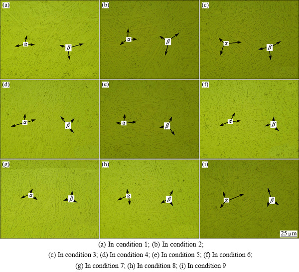
Fig. 8 Microstructures of deformed Ti-6Al-4V alloy in orthogonal experimental conditions
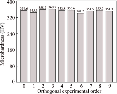
Fig. 9 Microhardnesses of deformed Ti-6Al-4V alloy under different orthogonal conditions
4.5 Optimization integration
For hot SCF process, the deformed materials need to ensure the shape and performance after forming, and ensure that the microstructures of the material do not change obviously. Considering the shape, the process parameters determined by the indicator of springback angle are A2B1C2D3. In terms of performance, the process parameters optimized by the indicators of yield strength in the three directions are A2B2C3D2. Considering the microstructure, by observing and measuring the microstructure of the deformed Ti-6Al-4V alloy, the suitable parameters of hot SCF is temperature of 700 ЎгC and the tensile speed of 5 mm/min.
For hot SCF, the shape of components should be ensured firstly. At the same time, the changes of the yield strength and microstructures must be taken into account. Therefore, based on the shape, performance and microstructure, the optimized process parameters of hot SCF are chosen comprehensively. They are temperature of 700 ЎгC, stretch velocity of 5 mm/min, post stretch percentage of 2% and dwelling time of 8 min.
5 Conclusions
1) The novel hot SCF technique has been proposed to produce the hard-to-form thin-walled titanium alloy components precisely due to the creep in the dwelling period.
2) Temperature is the main factor affecting the springback angle of components suffered from hot SCF. With the increase of temperature, the springback angle can be reduced significantly. Dwelling time, post stretch percentage and stretch velocity have a little effect on the springback angle.
3) For components suffered from hot SCF, the yield strength in 0Ўг direction increases, while those in directions of 45Ўг and 90Ўг fluctuate around the original value. The shape of some a phases changes from short thin grains to long slender ones, and the microhardness changes very little.
4) The optimized parameters with temperature of 700 ЎгC, stretch velocity of 5 mm/min, post stretch percentage of 2% and dwelling time of 8 min are achieved for the Ti-6Al-4V alloy sheet during hot SCF.
References
[1] LIU Y, QU Z D, WANG B X. Research development and application of Ti6Al4V alloy [J]. Ordnance Material Science and Engineering, 2005, 28 (1): 53-56. (in Chinese)
[2] EYLON D, SEAGLE S R. State of titanium in the USAЎӘThe first 50 years [M]// GORYNIN I V, USHKOV S S. Titanium 99: Science and Technology. St. Petersburg: CRISM Ў°PROMETEYЎұ, 2000: 37-41.
[3] VANDERHASTEN M, RABET L, VERLINDEN B. Ti-6Al-4V: Deformation map and modelisation of tensile behaviour [J]. Materials and Design, 2008, 29(6): 1090-1098.
[4] PARK M. Forming [M]//ASM Metal Handbook. 8th Edition. Ohio, ASM, 1970.
[5] MACHLIN E S. Applied voltage and the plastic properties of Ў°brillleЎұ rock salt [J]. Journal of Applied Physics, 1959, 30(7): 1109-1110.
[6] GERMAIN B M. Conduction heating of bars before hot forming [J]. Metallurgie, 1969, 101: 469.
[7] ULLRICH W. Direct resistance heating for economical hot forming [J]. Werkstatt und Betrieb, 1969, 99 (55): 339.
[8] VALANCE D. Productivity through resistance heating [J]. Metallurgia and Metal Forming, 1974: 369.
[9] KARUNASENA W G. Direct resistance heating in sheet metal forming [D]. Hong Kong: University of Hong Kong, 1977.
[10] MAKI S, HAMAMOTO A, SAITO S, MORI K. Hot stamping and press quenching of ultrahigh strength steel sheet using resistance heating [J]. Key Engineering Materials, 2007, 344: 309-316.
[11] MORI K, SAITO S, MAKI S. Warm and hot punching of ultra high strength steel sheet [J]. CIRP Annals-Manufacturing Technology, 2007, 57: 321-324.
[12] MAKI S, HARADA Y, MORI K, MAKINO H. Application of resistance heating technique to mushy state forming of aluminum alloy [J]. Journal of Material Processing Technology, 2002, 125-126: 477-482.
[13] MORI K, MAKI S, TANAKA Y. Warm and hot stamping of ultra high tensile strength steel sheets using resistance heating [J]. CIRP Annals-Manufacturing Technology, 2005, 54: 209-211.
[14] MORI K, MAKI S, ISHIGURO M. Improvement of product strength and formability in stamping of Al-Mg-Si alloy sheets having bake hardenability by resistance heat and artificial aging treatments [J]. International Journal of Machine Tools & Manufacture, 2006, 46: 1966-1971.
[15] JONES J J, MEARS L. A process comparison of simple stretch forming using both conventional and electrically-assisted forming techniques [C]//Proceedings of the 2010 International Manufacturing Science and Engineering Conference. Erie, PA, USA: MSEC2010: 623-631.
[16] OZTURK F, ECE R E, POLAT N, KOKSAL A. Assessment of electrical resistance heating for hot formability of Ti-6Al-4V alloy sheet [J]. Key Engineering Materials, 2011, 473: 130-136.
[17] FAN G Q, GAO L, HUSSAIN G, WU Z. Electric hot incremental forming: A novel technique [J]. International Journal of Machine Tool & Manufacture, 2008, 48(15): 1688-1692.
[18] POLEN L A, WEBER H J, HOUSTON T S. Titanium stretch forming apparatus and method: US 2007/0102493 A1 [P]. 2010-05-10.
[19] POLEN L A, HOUSTON T S, OWENS J E. Stretch forming apparatus with supplemental heating and method: US 2010/0071430 A1 [P]. 2010-03-25.
[20] MINAKAWA K, KESKAR A R, BARB A. Method and apparatus for hot forming elongated metallic bars: US 2007/0261461 A1 [P]. 2007-11-15.
[21] MINAKAWA K, KESKAR A R, BARB A. Method and apparatus for creep forming of and relieving stress in an elongated metal bars: US 2007/0261463 A1 [P]. 2007-11-15.
[22] GUO Zhi-hong, HOU Hua, ZHAO Yu-hong, QU Shu-wei. Optimization of AZ80 magnesium alloy squeeze cast process parameters using morphological matrix [J]. Transactions of Nonferrous Metals Society of China, 2012, 22(2): 411-418.
[23] BAI Yan, GAO Hong-ming, WU Lin, MA Zhao-hui, CAO Neng. Influence of plasma-MIG welding parameters on aluminum weld porosity by orthogonal test [J]. Transactions of Nonferrous Metals Society of China, 2010, 20(8): 1392-1396.
[24] WANG Xiao-hui, ZHENG Shi-li, XU Hong-bin, ZHANG Yi. Dissolution behaviors of Ta2O5, Nb2O5 and their mixture in KOH and H2O system [J]. Transactions of Nonferrous Metals Society of China, 2010, 20(10): 2006-2011.
[25] LI Heng, SHI Kai-peng, YANG He, TIAN Yu-li. Springback law of thin-walled 6061-T4 Al-alloy tube upon bending [J]. Transactions of Nonferrous Metals Society of China, 2012, 22(s2): s357-s363.
[26] WU Xin, HAN Fei, WANG Wei-wei. Effects of solution treatment and aging process on microstructure refining of semi-solid slurry of wrought aluminum alloy 7A09 [J]. Transactions of Nonferrous Metals Society of China, 2009, 19(s2): s331-s336.
[27] XIAO J. Key technologies of hot stretch-creep forming for titanium alloy sheet components [D]. Beijing: Beihang University, 2012. (in Chinese)
[28] LI X Q, XIAO J, LI D S, ZHANG C. A method for hot-stretch forming thin-walled titanium alloy components: ZL201110308987.X [P]. 2013.
[29] XIAO J J, LI D S, LI X Q, JIN C H, LI J L. Experimental research and numerical simulation of hot bulging tests of TC1 hemisphere part [J]. Forging and Stamping Technology, 2011, 36(6): 11-14.
[30] BRUSCHIA S, POGGIOB S, QUADRINIB F, TATAB M E. Workability of Ti-6Al-4V alloy at high temperatures and strain rates [J]. Materials Letters, 2004, 58(27-28): 3622-3629.
[31] XIAO J, LI D S, LI X Q, DENG T S. Constitutive modeling and microstructure change of Ti-6Al-4V during the hot tensile deformation [J]. Journal of Alloys and Compounds, 2012, 541: 346-352.
РӨҫьҪЬ1,2Ј¬АЙэ2Ј¬АоРЎЗҝ2Ј¬¶Ў ЕО2Ј¬ХФ ҝӯ2Ј¬»Жҹ@ХС2Ј¬РшГчҪш1
1. ұұҫ©УЎЛўС§Фә »ъөз№ӨіМС§ФәЈ¬ұұҫ© 102600Ј»
2. ұұҫ©әҪҝХәҪМмҙуС§ »ъРө№ӨіМј°ЧФ¶Ҝ»ҜС§ФәЈ¬ұұҫ© 100191
ХӘ ТӘЈәИИАӯЙмИдұдКЗТ»ЦЦјУ№ӨіЈОВДСіЙРОұЎұЪҪрКфЕчБПөДРВјјКхЎЈІЙУГЛДТтЛШЎўИэЛ®ЖҪХэҪ»ұнЈ¬УЕ»ҜБЛИИАӯЙмИдұдTi-6Al-4V°еІДөД4ёц№ӨТХІОКэЈәОВ¶ИЎўАӯЙмЛЩВКЎўІ№АӯЙмБҝәНұЈОВКұјдЎЈХэҪ»КФСйҪб№ыұнГчЈәОВ¶ИКЗУ°Пм»ШөҜҪЗөДЧоЦШТӘТтЛШЈ»СШАӯЙм·ҪПтіЙ0Ўг·ҪПтөДұдРОІДБПЗь·юУҰБҰФцјУЈ¬СШ45ЎгәН90Ўг·ҪПтөДЗь·юУҰБҰО§ИЖОҙұдРОІДБПөДЗь·юУҰБҰРЎ·¶О§ІЁ¶ҜЎЈҫӯ№эИИАӯЙмИдұдіЙРОЈ¬ұдРОІДБПОў№ЫЧйЦҜЦРaПаУЙ¶МПёҫ§БЈұдіЙіӨПёҫ§БЈЈ¬ұдРОІДБППФОўУІ¶ИФЪіЙРОЗ°әуұд»ҜәЬРЎЎЈЧЫәП»ШөҜҪЗЎўЗь·юЗҝ¶ИЦёұкХэҪ»·ЦОцҪб№ыәНІДБПОў№ЫЧйЦҜұд»ҜЗйҝцЈ¬өГіцБЛИИАӯЙмИдұдёҙәПіЙРОөДУЕ»Ҝ№ӨТХІОКэОӘЈәОВ¶И700 ЎгCЈ¬АӯЙмЛЩВК5 mm/minЈ¬І№АӯВК2%Ј¬ұЈОВКұјд8 minЎЈ
№ШјьҙКЈәTi-6Al-4VәПҪрЈ»ИИАӯЙмИдұдіЙРОЈ»»ШөҜЈ»ХэҪ»КФСйЈ»УЕ»Ҝ
(Edited by Yun-bin HE)
Foundation item: Project (51175022) supported by the National Natural Science Foundation of China; Project (51318040315) supported by the National Defense Pre-research of China; Project (09000114) supported by Initial Funding for the Doctoral Program of BIGC; Project (E-a-2014-13) supported by BIGC Key Project
Corresponding author: Dong-sheng LI; Tel/Fax: +86-10-82338283; E-mails: cnxiaojunjie@163.com; lidongs@buaa.edu.cn
DOI: 10.1016/S1003-6326(15)63619-6

