�绡���۶Թ�ҵ390A�Ͻ�����֯����ѧ���ܺ�Ħ��ѧ���ܵ�Ӱ��
��Դ�ڿ����й���ɫ����ѧ��(Ӣ�İ�)2021���8��
�������ߣ�Ali PaSa HEKIMOGLU Merve CALIS
����ҳ�룺2264 - 2276
�ؼ��ʣ�390A�Ͻ�����֯����ѧ���ܣ�Ħ��ѧ���ܣ��绡����
Key words��390A alloy; microstructure; mechanical properties; tribological properties; arc melting
ժ Ҫ��Ϊ�о��绡���۶�390A�Ͻ�����֯����ѧ���ܺ�Ħ��ѧ���ܵ�Ӱ�죬�Բ��ó����Ӧ�������Ʊ���390A�Ͻ��е绡���ۡ����ù�ѧ������ɨ��羵�۲�Ͻ������֯�����ò���Ӳ�ȷ�������������ԺϽ����ѧ���ܣ����������ʽĦ��ĥ���������Ħ��ѧ���ܽ����о��������������Ӧ�����͵绡���۵�390A�Ͻ��о����Ц�(Al)��Al-12Si�����ࡢ����Si��������-CuAl2����-Al5FeSi����-Al4FeSi2�� ��-Al15(FeMnCu)3Si2 �ࡣ�绡����ʹ��Щ��ľ���ϸ������(Al)��������������ɢ���Ӿ��ȣ��������������DZ�Բ�����Ӧ������Ʒ��ȣ��绡���ۺ�390A�Ͻ��Ӳ����102 HB��ߵ�118 HB������ǿ����130 MPa��ߵ�240 MPa���绡���۹���Ҳʹ390A�Ͻ����ĥ����ߣ�Ħ���������͡�
Abstract: To investigate the effect of the arc re-melting on the microstructure, mechanical and tribological properties of the 390A alloy, its ingot produced by the conventional induction melting method was subjected to the arc re-melting process. The microstructure of the 390A alloy was examined by OM and SEM. Mechanical properties of the 390A alloy were determined by the Brinell method and tensile tests. Tribological properties were investigated with a ball-on-disc type tester. It was observed that the microstructure of both conventional induction melted and arc re-melted 390A alloys consisted of ��(Al), eutectic Al-12Si, primary silicon particles, ��-CuAl2, ��-Al5FeSi, ��-Al4FeSi2, and ��-Al15(FeMnCu)3Si2 phases. Re-melting with the arc process caused grain refinement in these phases. In addition, after this process, the ��(Al) phase and primary silicon particles were dispersed more uniformly, and sharp edges of primary silicon particles became round. The arc re-melting process resulted in an increase in the hardness of the 390A alloy produced by the conventional method from 102 HB to 118 HB and the tensile strength from 130 to 240 MPa. It also caused an increase in the wear resistance of the 390A alloy and a decrease in the friction coefficient.
Trans. Nonferrous Met. Soc. China 31(2021) 2264-2276
Ali PaSa HEKIMOGLU, Merve CALIS
Department of Mechanical Engineering, Recep Tayyip Erdogan University, 53100, Rize, Turkey
Received 17 September 2020; accepted 2 March 2021
Abstract: To investigate the effect of the arc re-melting on the microstructure, mechanical and tribological properties of the 390A alloy, its ingot produced by the conventional induction melting method was subjected to the arc re-melting process. The microstructure of the 390A alloy was examined by OM and SEM. Mechanical properties of the 390A alloy were determined by the Brinell method and tensile tests. Tribological properties were investigated with a ball-on-disc type tester. It was observed that the microstructure of both conventional induction melted and arc re-melted 390A alloys consisted of ��(Al), eutectic Al-12Si, primary silicon particles, ��-CuAl2, ��-Al5FeSi, ��-Al4FeSi2, and ��-Al15(FeMnCu)3Si2 phases. Re-melting with the arc process caused grain refinement in these phases. In addition, after this process, the ��(Al) phase and primary silicon particles were dispersed more uniformly, and sharp edges of primary silicon particles became round. The arc re-melting process resulted in an increase in the hardness of the 390A alloy produced by the conventional method from 102 HB to 118 HB and the tensile strength from 130 to 240 MPa. It also caused an increase in the wear resistance of the 390A alloy and a decrease in the friction coefficient.
Key words: 390A alloy; microstructure; mechanical properties; tribological properties; arc melting
1 Introduction
Aluminum (Al)-silicon (Si) based alloys are widely used in industrial applications due to their many advantages. These advantages are easy and economical production, high corrosion resistance, low thermal expansion coefficients, adequate strength values for many applications, lower density, and higher specific strength (strength/ density) than many alloys [1-3]. Especially, their lower density, higher specific strength, and higher corrosion resistance make Al-Si alloys attractive for the production of parts or components produced in areas such as automotive, defense, and aviation industries where lightness and, therefore, fuel- saving are at the forefront [4,5]. Engine or cylinder blocks, pistons, intake manifolds, oil pans, carburetors, transmission boxes, engine coil windings, transistor coolants, data recording discs, accumulators, warheads, and rocket bodies are some of these parts and components [4,6,7].
Hardness, mechanical properties and tribological properties are the most important factors in determining the usage areas of Al-Si alloys. These properties of Al-Si alloys differ significantly according to their silicon contents [8,9]. Al-Si alloys containing lower amount of silicon than the eutectic composition (~12.6 wt.% Si) exhibit higher strength and ductility, while those containing higher amount of silicon than the eutectic composition exhibit higher hardness, wear-resistance, and lower thermal expansion coefficient [8-11]. Lower strength and ductility of the hypereutectic Al-Si alloys compared to hypoeutectic Al-Si alloys, are especially due to the formation of more coarser and sharp-edged primary silicon particles in their microstructure [8,10]. Apart from them, particle size and morphology of the other phases such as ��(Al) and eutectic silicon particles in the microstructure of Al-Si alloys are also influential factors on the mechanical properties of these alloys [8,10,12,13]. Therefore, many studies have been carried out to reduce the size of ��(Al) grains and silicon particles in the microstructure of the Al-Si alloys [8,12-16]. The addition of alloying element or grain refiner, rapid cooling, and heat treatment applications after casting have been the most common methods to reduce and/or change the size and/or the morphology of these phases [17-20]. In a recent study, it has been revealed that high pouring temperature causes rapid cooling or high cooling rate due to the increase in the temperature gradient, and as a result, a microstructure consisting of fine grains and more homogeneously distributed phases [17,21]. Very high pouring temperatures can easily occur in electric arc melter (furnaces) compared to other melting furnaces, and these furnaces are currently preferred in the casting of metals with a high melting temperature in practice. There is no study investigating the material characteristics of hypereutectic Al-Si alloys produced with electrical arc melting furnaces. In this study, the material properties of the commercial 390A alloy ingot produced by the conventional induction melting method have been investigated before and after it has been re-melted and solidified in the arc-melter furnace to reveal the effects of the arc re-melting process on the properties of hypereutectic Al-Si alloys. The results obtained from the microstructural examinations and mechanical properties tests of the Al-Si alloy samples produced by both conventional induction melting and electric arc melting methods have been compared with each other.
2 Experimental
2.1 Alloy preparation and microstructure observation
390A alloy (Al-17Si-4Cu-0.6Mg-1Zn) was produced by the induction melting process. Commercial 390A alloy ingot was used in the production of the alloy. The alloy was melted in a medium frequency induction melting furnace and poured at a temperature of approximately 760 ��C into a conical shaped SAE 8620 steel mould at room temperature. The obtained alloy ingot was re-melted in an arc melter furnace with a capacity of 5-20 g and at 3500 ��C. Re-melting and solidification processes were performed on a water- cooled copper crucible plate with a trough-shaped mould which was located on the base of the melting chamber of the arc furnace. To eliminate the inefficiency of mixing under an electric arc, homogeneously mixed material ingot produced by using the induction melting method above mentioned was used in the arc re-melting process. High purity argon was used as the protective gas in the melting chamber. After the re-melting, the alloy ingot was cooled to room temperature in the melting chamber. Chemical compositions of the alloy samples were determined by the inductively coupled plasma-optical emission spectrometry (ICP-OES) technique. The properties of the produced alloy after both induction melting and arc melting were examined. Test sample preparation process sequence from alloy ingot and technical drawing of the samples are given in Fig. 1.
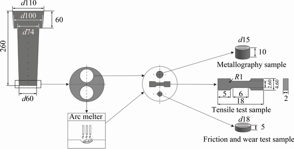
Fig. 1 Test sample preparation process sequence from alloy ingot and technical drawing of samples (unit: mm)
The microstructures of the alloy samples were investigated with both optical and scanning electron microscopy techniques. SEM investigations were performed using the backscatter electron imaging mode at an acceleration voltage of 15 kV. The phases in the microstructure of the alloy samples were identified by metallographic observations and X-ray diffraction (XRD) analyses. These analyses were performed in flat samples at a scanning range of 20��-90�� using a Cu K�� radiation source at a scanning rate of 3 (��)/min and a wavelength of 1.54059  . Grain sizes of the phases were calculated by a standard linear intercept method according to the ASTM E112��10 standard [22]. Shape factors in terms of aspect ratio (AR) were defined according to the following equation [23]:
AR=dmax/dmin (1)
where dmax is the largest diameter, and dmin is the smallest diameter orthogonal to dmax.
2.2 Hardness and tensile tests
Technical drawings of the hardness and tensile test samples are given in Fig. 1. These test samples were produced by machining the alloy ingots with a water jet. The hardness values of the alloy samples were determined by using a Brinell method with a ball diameter of 2.5 mm and a load of 612.5 N. At least six hardness measurements and tensile tests were made in each alloy sample and the average values obtained from these tests were taken as the hardness, tensile strength, and elongation to fracture values. Tensile tests were performed at a deformation rate of 1��10-3 s-1. By using the data obtained from tensile tests, the quality indexes of the alloys were calculated using the following equation [18]:
Q=��b+klg �� (2)
where Q is the quality index (MPa), ��b is the tensile strength (MPa), �� is the elongation to fracture value (%), and k is the material constant for aluminum alloys (150 MPa).
2.3 Wear tests
Wear tests were carried out by using a ball-on-disc type tribotester according to ASTM G99 standard. This tester consists of an electric motor, a disc on which the test specimen is placed, a sample holder, an abrasive ball, a ball holder, a load, a load arm, a load sensor and a computer-aided control unit. The dimensions of wear test samples are given in Fig. 1. Wear test samples were polished with 1200# grit abrasive paper before the tests. 100Cr6 steel abrasive ball having a hardness of ~658 HB and a diameter of 6 mm was used in the wear tests. These tests were carried out under a load of 5 N and at a sliding speed of 0.15 m/s for a sliding distance of 1000 m. These test parameters were determined by considering the studies [24-26] made on aluminum alloys with this tester. Each wear test was performed with a new sample and ball. The coefficients of friction of the alloys were calculated by dividing the frictional force by normal load. The amount of wear occurring in the test samples was calculated as volume loss. The volume loss values of the alloys were determined by dividing the measured mass loss values by the density values. A balance with an accuracy of ��0.01 mg was used to determine the mass loss values.
3 Results and discussion
3.1 Microstructure
The chemical composition of the 390A alloy is given in Table 1.
Table 1 Chemical composition of 390A alloy (wt.%)

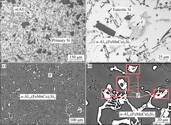
Fig. 2 OM (a, b) and SEM (c, d) micrographs showing microstructure of induction-melted 390A alloy

Fig. 3 OM (a, b) and SEM (c, d) micrographs showing microstructure of arc re-melted 390A alloy
Table 2 Chemical compositions of phases observed in microstructures of tested alloy (wt.%)
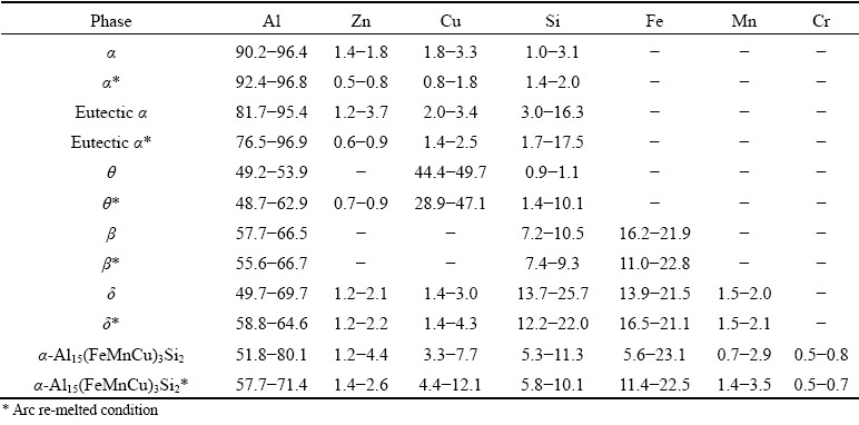
The microstructures of the induction- and arc-melted alloy samples are shown in Figs. 2 and 3, respectively. EDS analysis results of the phases are given in Table 2. It was observed that the microstructure of 390A alloy produced by induction melting method consisted of ��(Al), eutectic Al-Si phase and primary silicon particles, ��-CuAl2, ��-Al5FeSi, ��-Al4FeSi2, and ��-Al15(FeMnCu)3Si2 phases (Fig. 2). The eutectic Si particles have a thin and long shape, while the primary silicon particles have a relatively large or coarse irregular shape with sharp-edged corners. It is also observed that intermetallics ��, ��, ��, and ��-Al15(FeMnCu)3Si2 phases are adjacent to each other in the microstructure. The formation of the phases in the microstructure can be explained according to the solidification behavior of the alloy. The phases of ��-Al4FeSi2, ��-Al5FeSi, and ��-Al15(FeMnCu)3Si2 which are seen in the microstructure of 390A alloy are intermetallic compounds formed by the reaction of impurity elements with alloying elements. The ��-Al4FeSi2 phase starts to precipitate at approximately 1000 ��C while the �� phase is formed by the peritectic reaction of the Liquid + ��-Al4FeSi2����-Al5FeSi+Si at ~850 ��C [27]. The �� phase having relatively high silicon content is transformed into the �� phase by a lower silicon content with diffusion mechanism. The observation of the �� and �� phases together in the microstructure of the alloy may have resulted from incomplete diffusion due to non-equilibrium cooling conditions. The ��-Al15(FeMnCu)3Si phase having a skeletal structure is formed by the reaction of Liquid + ��-Al5FeSi��Al+Si+��-Al15(FeMnCu)3Si2 [28]. Based on Refs. [29,30], the formation tendency of the iron-based intermetallic phases in the micro- structure of the Al-Si alloys can be predicted depending on the sludge factor (SF, Eq. (3)) and Fe/Mn mole ratio:
SF=x1+2x2+3x3 (3)
where x1, x2, and x3 represent the mole fractions of Fe, Mn, and Cr, respectively.
For the 390A alloy sample tested, the sludge factor and Fe/Mn ratio were calculated as 1.29 and 8.25, respectively. It is suggested that if the sludge factor is higher than 1.25, iron-rich intermetallic phases are formed, and the ratio of these intermetallic phases increases with increasing Fe/Mn ratio [29,30]. It is also suggested that if this ratio is greater than 2, the �� phase will react with impurity elements Mn and Cr, and the ��-Al15(FeMnCu)3Si2 phase is formed. Our findings are compatible with Refs. [29,30] about sludge factor and Fe/Mn ratio related to the formation of intermetallic phases in Al-Si alloys.
According to the Al-Si phase diagram, the primary silicon phase solidifies before the ��(Al) phase since it has a higher melting point [31]. As the solidification continues, the silicon content of the liquid metal decreases, and the aluminum content increases. The copper-rich intermetallic ��-CuAl2 phase is formed by the reaction of aluminum with copper when the temperature of the liquid metal drops to ~590 ��C [10,32]. When the composition and temperature of the liquid metal decrease the eutectic point (approximately 87.4 wt.% Al, 12.6 wt.% Si and 577 ��C), a eutectic Al-Si phase is formed [33]. The eutectic Al-Si phase consists of the thin and long shape Si particles and aluminum matrix. The ��(Al) phase having grain or dendritic form in the Al-Si alloys is known to be formed due to the non-equilibrium cooling conditions.

Fig. 4 Bar chart showing average grain size and grain number of ��(Al) phase (a) and primary silicon particles (b) of micrographs in Figs. 2 and 3
The 390A alloy re-melted with arc exhibited a microstructure having the same phases with induction-melted 390A alloy, that is to say, no different phases are formed in the arc-melted 390A alloy, as seen in Figs. 2 and 3. But, it is observed in Fig. 4 that the average grain sizes of the ��(Al) grains and primary silicon particles decrease from 41.0 to 35.3 ��m and from 28.4 to 21.5 ��m, respectively. In addition, these phases display a more uniform and equiaxed distribution. The changes in the grain size of the ��(Al) phases due to the arc melting process can be explained in terms of cooling rate, nucleation, and subsequent growth mechanisms. Compared to the induction melting method, the pouring temperature in the arc melting process is higher due to high electrical arc energy. A higher pouring temperature resulted in an increase in the cooling rate (R) according to the following equation:
R=h(T-To)/(c��z) (4)
where h is the heat transfer coefficient, T is the pouring temperature, To is the mould temperature, c is the specific heat capacity, �� is the density, and z is the thickness of the sample [34]. As the cooling rate increases, the formation temperature of the phases changes, and the magnitude of this change increases. The liquidus temperature and heat extraction also increase as the cooling rate increases. Therefore, the liquid metal is cooled to a lower temperature than its melting point in equilibrium conditions [35]. This causes the formation of more nuclei due to supercooling and nucleation to be easier and faster. Nucleation increases in proportion to the cooling rate. However, an increase in the cooling rate and a decrease in the solidification time of the molten metal slow down diffusion. This causes an increase in the number, restriction of grain growth, refining and more homogeneous distribution of the ��(Al) grains [12,13]. The reduction of the grain size of the silicon particles after re-melting with arc can be explained based on diffusion mechanisms. The primary silicon phase is known to grow by bonding Si atoms to the surfaces of primary silicon particles [36]. For this reason, the diffusion of Si atoms is important for the growth of primary silicon particles. The diffusion of Si atoms becomes difficult with increasing cooling rate. This suppresses the growth of primary silicone particles. Therefore, the primary silicon size decreases with increasing cooling rate. It is observed that the shape factor of the primary silicon particles decreases from 1.79 to 1.38, and their sharp edges or corners are rounded to a certain extent. The decrease in aspect ratio is thought to be caused by the decrease in the difference between dmin and dmax values in Eq. (1) as a result of the rounding of the silicon particles after the arc-remelting process. It is also observed that ��, ��, ��, and ��-Al15(FeMnCu)3Si2 phases are refined to a small extent, and eutectic silicon particles take a short and thick form after re-melting with the arc process. These morphological changes in the phases are thought to be due to the higher cooling rate which restricts grain growth [32,37].
The XRD patterns of the tested alloy produced in both induction and arc melting methods are given in Fig. 5. The same XRD patterns were obtained from the induction- and arc-melted alloys. These patterns show that the 390A alloy exhibits a microstructure consisting of the same phases when produced by both induction and arc melting.
3.2 Mechanical properties
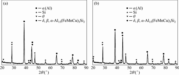
Fig. 5 XRD patterns of induction-melted (a) and arc re-melted (b) 390A alloys
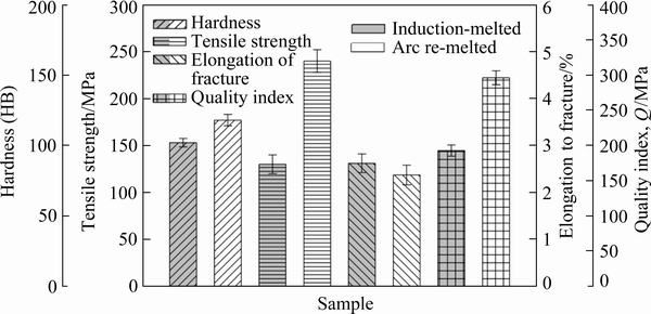
Fig. 6 Bar charts showing hardness, tensile strength, elongation to fracture, and quality index of tested alloys
The values of hardness, tensile strength, and elongation to fracture of both induction- and arc- melted 390A alloys are given in Fig. 6. Re-melting with arc caused the hardness of the alloy to increase from 102 HB to 118 HB, and tensile strength increased from 130 to 240 MPa. But elongation to fracture value decreased from 2.67% to 2.37%. The significant increase in tensile strength of the alloy after the arc re-melting process also led to a significant increase in the quality index value of the 390A alloy. Improvements in the hardness and tensile strength values of the tested alloy due to arc re-melting can be explained based on dispersion hardening and grain refining mechanisms. It is well known that second phase particles dispersed in the microstructure of multiphase alloys prevent the movement of dislocations and thus lead to an increase in strength [38]. It is clear that the primary silicon particles dispersed in the soft matrix of the 390A alloys are an obstacle to the movement of dislocations, and an increase in the number of silicon particles as a result of the arc re-melting process causes an increment in the number of these obstacles. The effect of obstacles faced by dislocations on the material strength has been explained in detail in Ref. [39]. It has been revealed that if dislocations pass between the obstacles, they leave small dislocation loops around them [39]. These dislocation cycles apply back stress that must be overcome in order for dislocations moving in the sliding plane to continue their movement. This means that higher shear stress is required for deformation to occur or/and continue. Thus, dispersed silicon particles lead to increased strain hardening during the period when loops are built up around the particles. In this case, the force required for the movement of dislocations between two particles (��) is expressed by the following equation:
��=Gb/d1 (5)
where G is the shear modulus, b is the magnitude of Burgers vector, and d1 is the distance between two particles [40]. According to Eq. (5), as the distance between the particles decreases due to the arc re-melting process, the force required for the movement of the dislocations increases, and as a result, the material strength increases after the arc re-melting process. Figure 4 shows that the number of the primary silicon phase particles of the arc re-melted alloys is more than that of the alloy produced by the induction melting method. It is thought that the increase in the number of silicon particles contributes to the increase in strength as it leads to an increase in the number of obstacles in front of the dislocations. Due to the arc re-melting process, the decrease of sharp edges and corners of primary silicon particles may have also contributed to the increase in strength. It has been revealed in detail that reducing the sharp edges and corners of primary silicon particles in the microstructure of Al-Si alloys, that is rounding, improves the mechanical properties of these alloys [8,36,41]. Although the increase observed in the strength of the 390A alloy with the arc re-melting process is thought to be mainly due to the change in the shape and distribution of the primary silicon particles, grain refining observed in the other phases, especially in the ��(Al) phase, may also have contributed to the increase in strength. Several studies [7,12,13,36,41-43] show that grain refining in the ��(Al) phase contributes to the increase of the strength of Al alloys. The relationship between grain size and strength in metals is generally expressed by the Hall-Petch equation [26]:
��=��0+kd-1/2 (6)
where �� is the strength of an alloy, d is the average grain size, ��0 is the strength of the single crystal, and k is a material constant. According to this equation, the strength of an alloy is inversely proportional to the square root of the grain size, and material strength increases with decreasing grain size.
3.3 Fracture surfaces
SEM micrographs of the tensile fracture surfaces of the tested alloy samples are given in Fig. 7. These micrographs show that the fracture surfaces of the alloy samples generally consist of cleavage planes, dimples, and tear ridges, and also arc melted alloy samples exhibit a finer-grained fracture surface. The fracture surface characteristics of the alloy test samples can be explained based on the properties and sizes of the phases. It has been revealed in previous studies [15,24,41,44] that the fracture mechanism of Al-Si based alloys depends on the size and distribution of the silicon crystals, the easy fracture behavior of the silicon crystals, the strength of the matrix to bind to the silicon crystals, ductile ��(Al) phase, and intermetallic phases. It is well known that silicon is a hard and brittle material and micro-cracks are very often found in the crystal lattice structure of such brittle materials [45]. These micro-cracks cause stress accumulation in silicon crystals, and this can result in progress or propagation of the crack even if the applied external load does not exceed the strength value of the material. When the crack passes through the silicon crystal, the fracture occurs, which is called transcrystalline fracture. In this case, the fracture takes place as cleavage, and the planes in which the cleavage occurs are called cleavage planes. There is no difference in the relative positions of the atoms on the separated surfaces from their previous positions in this type of fracture. Cleavage planes in silicon are generally characterized as the planes of {111} in which the atoms are most closely packed and have low surface energy. More cracks occur in larger crystals in Al-Si alloys [46]. This is due to the fact that the stress formed in the matrix is transferred to the coarse silicon crystals at a higher rate [47]. High-rate stress transfer causes the strength of the silicon crystals to be easily overcome and crack initiation and/or propagation. Tear ridges observed on the fracture surfaces of the tested alloy are thought to be formed by the plastic flow of the aluminum-rich ductile phases in the region of the local neck before the fracture as it has been stated in Ref. [45]. The dimples are nucleated in small discontinuous voids as a result of the activation of the slip systems in successive microregions due to the energy absorbed during plastic deformation [45]. Microvoids grow with the effect of triaxial stress before cracks initiate and take a dimple form. This process can be seen as a plastic flow on the surface and is accepted as a sign of ductile fracture. It is seen that the dimples on the surface of the tested alloy samples are formed in aluminum-rich ductile phase regions. It is observed that dimples have different morphologies. This is thought to be due to the differences in active local stress and strain. The fracture surfaces of the arc-melted alloys exhibit a topography consisting of finer dimples and smaller cleavage planes, together with more tightly aligned tear ridges. This is thought to be due to grain refining of the phases in the microstructure of the tested alloy with the effect of arc re-melting.

Fig. 7 SEM micrographs showing fracture surfaces of tensile test samples of induction-melted (a) and arc re-melted (b) alloys
The micrographs of the longitudinal sections below the fracture surfaces of tensile test samples are presented in Fig. 8. These micrographs show that the fracture (main crack) occurs in the interdendritic eutectic regions and has a zigzag profile. When the fracture line reaches the �� dendrites, it preferably propagates along the dendrite boundaries or through brittle phases such as Si, ��, ��, ��, and ��-Al15(FeMnCu)3Si2 located in the dendrite borders [48]. In the presence of intermetallic phases such as ��, ��, ��, and ��-Al15(FeMnCu)3Si2 at the dendrite borders, the progress of the fracture through these phases can be due to the fact that these phases are more brittle than the ��(Al) phase [9]. Figure 8 also shows that secondary cracks take place on the fracture surfaces, internal cracks on the longitudinal sections of the fracture surfaces, and micronecks on the fracture line. Secondary and internal cracks are formed in the primary silicon particles due to their brittleness while micronecks may be formed due to local plastic deformation of the parts of the ductile �� phase between the brittle phases.
3.4 Tribological properties

Fig. 8 SEM micrographs showing longitudinal sections below fracture surfaces of tensile test samples

Fig. 9 Bar charts showing wear volume and friction coefficient values of tested alloy samples
The bar charts showing the average friction coefficient and wear loss values of the induction- and arc-melted 390A alloys are given in Fig. 9. This figure shows that arc-melted 390A alloy exhibits lower friction coefficient and wear loss values. The lower friction coefficients of the alloys produced by the arc melting method may be due to the higher hardness and strength of these alloys. The decrease in friction coefficient with the increase in hardness and strength of Al-Si alloys can be explained based on the welding bond theory as previously suggested in Refs. [14,49]. According to this theory, the contacting surfaces are initially in contact at certain roughness points, and the load is carried by surfaces of these contact points. When the surfaces come in contact, bonds are formed primarily between the oxide layers on the surfaces. Accordingly, the load is expressed as
W=AP�� (7)
where W is the normal load, A is the real contact area, and Po is the strength of the material. After the load is applied, due to very high pressures at contact points, oxide layers break and metallic contact occurs [24,49]. At the points where metallic contact occurs with the effect of high pressure, microscopic source bonds are formed in the form of molecular bonds. These welding bonds are much stronger than the oxide layer and must be broken for the relative movement of the contacting surfaces. In addition, the plastic deformation that occurs when the hard roughs move in the soft surface and the resistance that occurs after the interaction of the particles formed as a result of this deformation also affect the friction force. In this case, the friction force (F) can be expressed by the following formula:
F=As+Pe (8)
where s is the shear force required for breaking welding bonds, and Pe is the force required for hard roughs to pass through the soft matrix. Pe can be neglected because it is much smaller than As. In this case, the friction force can be expressed as
F=As=Ws/P�� (9)
According to Eq. (9), an increase in the material strength causes the friction forces and the friction coefficient to decrease [24,49]. Lower elongation to the fracture may also have contributed to obtaining a lower friction coefficient from the alloy sample produced by the arc re-melting. As the elongation to fracture (ductility) decreases, less plastic flow occurs on the surface of the materials and this leads to a decrease in friction forces. The reduction in friction force results in a lower coefficient of friction.
The fact that the arc re-melted alloy has lower wear loss (higher wear resistance) may be due to higher hardness and strength of this alloy. It is well known that the wear resistance of materials increases with increasing strength and hardness values according to adhesive wear law and Archard equation [50]. Grain refining caused by the arc re-melting in hard and brittle intermetallic phases, and especially the primary silicon phase, may have contributed to the reduction in the abrasive effect of these phases and thus to the reduction in wear loss. More homogeneous dispersion of primary silicon particles in the microstructure of the alloy as a result of arc re-melting may have also contributed to the increase in the wear resistance of the alloy.
Smearing and delamination are observed to be the main features of the worn surface of the alloy samples in Figs. 10(a) and (b). Fine scratches are also observed on the worn surfaces. It is known that smeared layers on the worn surfaces of Al-Si alloys are formed by the adhesion of the plastically deformed surface layer on the sample surface with the effect of ball pressure and temperature [14]. The formation of smeared layers on the worn surface can be considered as a sign of an adhesive wear mechanism. It is thought that the delamination occurring on the wear surfaces is caused by fracture of the smeared brittle layers under the effect of load and heat. Fine scratches on the worn surface are caused by the scraping effect of hard silicon wear particles. The formation of scratches on worn surfaces also indicates the presence of an abrasive wear mechanism in the tested alloy.

Fig. 10 SEM micrographs showing wear surfaces of induction-melted (a) and arc re-melted (b) alloy samples
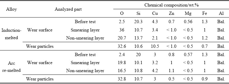
The SEM micrographs showing the wear debris collected from the disc surface are given in Fig. 11. EDS analysis results showing the chemical composition of the surface and wear particles of the alloy samples are given in Table 3. SEM micrographs show that wear debris of the tested alloy samples is a mixture of different size particles. It is thought that the size differences in wear particles are due to the grinding of these particles between disc and ball after leaving the surface. The chemical composition of the wear particles is found to be more or less the same as that of the smearing layer of the wear samples, as shown in Table 3. This observation can be an indication that the wear particles are formed as a result of breaking the smeared layers. It is also observed that the oxygen rate on the wear sample surface increases after the friction wear test. This can be due to the facilitation of oxide formation on the surface with the effect of pressure and temperature during the tests. The findings are consistent with the studies [51,52] regarding the formation and structure of wear particles in alloys containing aluminum.

Fig. 11 SEM micrographs showing wear particles of induction-melted (a) and arc re-melted (b) alloy samples
Table 3 EDS analysis results of wear surfaces and wear particles of alloy samples
4 Conclusions
(1) The microstructure of the 390A alloy consists of ��(Al), eutectic Al-Si phase, primary silicon particles, ��-CuAl2, ��-Al5FeSi, ��-Al4FeSi2 and ��-Al15(FeMnCu)3Si2 phases.
(2) Re-melting with the arc process of the 390A alloy causes grain refinement in the phases of the microstructure of the 390A alloy. This process also results in the number of primary silicon particles to increase, their sharp edges or corners to be rounded, and more uniform distribution in the microstructure of the alloy.
(3) Re-melting with arc process significantly increases the hardness and strength of the 390A alloy.
(4) Re-melting with arc increases the wear resistance of the 390A alloy, but decreases its friction coefficient.
References
[1] ARTHANARI S, JANG J C, SHIN K S. Corrosion studies of high pressure die-cast Al-Si-Ni and Al-Si-Ni-Cu alloys [J]. Journal of Alloys and Compounds, 2018, 749: 146-154.
[2] SHAHA S K, CZERWINSKI F, KASPRZAK W, FRIEDMAN J, CHEN D L. Effect of solidification rate and loading mode on deformation behavior of cast Al-Si-Cu- Mg alloy with additions of transition metals [J]. Materials Science and Engineering A, 2015, 636: 361-372.
[3] SHAHA S K, CZERWINSKI F, KASPRZAK W, FRIEDMAN J. CHEN D L. Microstructure and mechanical properties of Al-Si cast alloy with additions of Zr-V-Ti [J]. Materials & Design, 2015, 83: 801-812.
[4] JAVIDANI M, LAROUCHE D. Application of cast Al-Si alloys in internal combustion engine components [J]. International Materials Reviews, 2014, 59: 132-158.
[5] JIANG W M, FAN Z T, LIU D J, LIAO D F, ZHAO Z, DONG X P, WU H B. Influence of process parameters on filling ability of A356 aluminium alloy in expendable pattern shell casting with vacuum and low pressure [J]. International Journal of Cast Metals Research, 2012, 25(1): 47-52.
[6] LI Y G, YANG Y, WU Y Y, WANG L Y, LIU X F. Quantitative comparison of three Ni-containing phases to the elevated- temperature properties of Al-Si piston alloys [J]. Materials Science and Engineering A, 2010, 527: 7132-7137.
[7] YU W B, YUAN Z X, GUO Z P, XIONG S M. Characterization of A390 aluminum alloy produced at different slow shot speeds using vacuum assisted high pressure die casting [J]. Transactions of Nonferrous Metals Society of China, 2017, 27: 2529-2538.
[8] HEKIMOGLU A P, HACIOSMANOGLU M. Microstructure and mechanical properties of Al-(2-30)Si alloys [C]//Proceedings of the 3rd International Conference on Material Science and Technology in Cappadocia (IMSTEC��18). Nevsehir, Turkey, 2018: 169-174.
[9] HEKIMOGLU AP, CALIS M, AYATA G. Effect of strontium and magnesium additions on the microstructure and mechanical properties of Al-12Si alloys [J]. Metals and Materials International, 2019, 25: 1488-1499.
[10] HEKIMOGLU A P, HACIOSMANOGLU M. Effect of copper and magnesium additions on the structural, mechanical and tribological properties of the Al-17Si alloy [J]. International Journal of Engineering Research and Development, 2019, 11: 685-694.
[11] HU Z H, WU G H, XU J, MO W F, LI Y L, LIU W C, ZHUANG L, DING W J, QUAN J, CHANG Y W. Dry wear behavior of rheo-casting Al-16Si-4Cu-0.5Mg alloy [J]. Transactions of Nonferrous Metals Society of China, 2016,26: 2818-2829.
[12] JIANG W M, FAN Z T, DAI Y C, LI C. Effects of rare earth elements addition on microstructures, tensile properties and fractography of A357 alloy [J]. Materials Science and Engineering A, 2014, 597: 237-244.
[13] JIANG W M, FAN Z T, CHEN X, WANG B J, WU H B. Combined effects of mechanical vibration and wall thickness on microstructure and mechanical properties of A356 aluminum alloy produced by expendable pattern shell casting [J]. Materials Science and Engineering A, 2014, 619: 228-237.
[14] HEKIMOGLU A P, HACIOSMANOGLU M, BAKI M. Effect of zinc contents on the structural, mechanical and tribological properties of EN AC-48100 (Al-17Si-4Cu-Mg) alloy [J]. Journal of the Faculty of Engineering and Architecture of Gazi University, 2020, 35: 1799-1814.
[15] HEKIMOGLU A P, AYATA G. Effect of strontium and strontium-magnesium additions on the microstructure and mechanical properties of hypereutectic Al-17Si alloy [J]. Pamukkale University Journal of Engineering Sciences, 2019, 25: 49-55.
[16] ZUO K S, ZHANG H T, HAN X, JIA H L, QIN K, CUI J Z. Effects of Cr and cooling rate on segregation and refinement of primary Si in Al-20wt.%Si alloy [J]. International Journal of Metal Casting, 2014, 8: 55-62.
[17] XU C L, WANG H Y, QIU F, YANG Y F, JIANG Q C. Cooling rate and microstructure of rapidly solidified Al-20wt.%Si alloy [J]. Materials Science and Engineering: A, 2006, 417: 275-280.
[18] CACERES C H. Microstructural effects on the strength ductility relationship of Al-7Si-Mg casting alloys [J]. Materials Science Forum, 2000, 331-337: 223-228.
[19] HAZRA B, BARANWAL P, BERA S, SHOW B K. Improvement in dry sliding wear resistance of Al-17Si-5Cu alloy after an enhanced heat treatment process [J]. Transactions of Nonferrous Metals Society of China, 2018,28: 1705-1713.
[20] LI M, LI Y, BI G, HUANG X, CHEN T, MA Y. Effects of melt treatment temperature and isothermal holding parameter on water-quenched microstructures of A356 aluminum alloy semisolid slurry [J]. Transactions of Nonferrous Metals Society of China, 2018,28: 393-403.
[21] DAMAVANDI E, NOUROUZI S, RABIEE S M, JAMAATI R. Effect of ECAP on microstructure and tensile properties of A390 aluminum alloy [J]. Transactions of Nonferrous Metals Society of China, 2019, 29: 931-940.
[22] Standard test methods for determining average grain size [S]. West Conshohocken, PA: ASTM International, 2010.
[23] NIKANOROV S P, OSIPOV V N, REGEL L I. Structural and mechanical properties of directionally solidified Al-Si alloys [J]. Journal of Materials Engineering and Performance, 2019, 28: 7302-7323.
[24] ALEMDAG Y, BEDER M. Microstructural, mechanical and tribological properties of Al-7Si-(0-5)Zn alloys [J]. Materials & Design, 2014, 63: 159-167.
[25] ALEMDAG Y, BEDER M. Effects of zinc content on strength and wear performance of Al-12Si-3Cu based alloy [J]. Transactions of Nonferrous Metals Society of China, 2019, 29: 2463-2471.
[26] HEKIMOGLU A P, CALIS M. Effects of titanium addition on structural, mechanical, tribological, and corrosion properties of Al-25Zn-3Cu and Al-25Zn-3Cu-3Si alloys [J]. Transactions of Nonferrous Metals Society of China, 2020, 30: 303-317.
[27] HOU L, CAI Y, CUI H, ZHANG J. Microstructure evolution and phase transformation of traditional cast and spray- formed hypereutectic aluminium-silicon alloys induced by heat treatment [J]. International Journal of Minerals, Metallurgy, and Materials, 2010, 17: 297-306.
[28] WANG M. Control of morphology Al-Fe-Si phase in Al-Si-Cu hypoeutectic alloy [D]. West Lafayette: Purdue University, 2014.
[29] TIMELLI G, BONOLLO F. The influence of Cr content on the microstructure and mechanical properties of AlSi9Cu3(Fe) die-casting alloys [J]. Materials Science and Engineering A, 2010, 528: 273-282.
[30] NEMRI Y, GUEDDOUAR B, BENAMAR M E A, SAHRAOUI T, CHIKER N, HADJI M. Effect of Mg and Zn contents on the microstructures and mechanical properties of Al�CSi�CCu�CMg alloys [J]. International Journal of Metalcasting, 2018, 12: 20-27.
[31] ASM International Handbook Committee. ASM handbook: Alloy phase diagrams [M]. Volume 3. New York: ASM International, 2016.
[32] PRABHUDEV M S, AURADI V, VENKATESWARLU K, SIDDALINGSWAMY N H, KORI S A. Influence of Cu addition on dry sliding wear behaviour of A356 alloy [J]. Procedia Engineering, 2014, 97: 1361-1367.
[33] SHANKAR S, RIDDLE Y W, MAKHLOUF M M. Nucleation mechanism of the eutectic phases in aluminum�C silicon hypoeutectic alloys [J]. Acta Materialia, 2004, 52: 4447-4460.
[34] WATERLOO G, JONES H. Microstructure and thermal stability of melt-spun Al-Nd and Al-Ce alloy ribbons [J]. Journal of Materials Science, 1996, 31: 2301-2310.
[35] SHABESTARI S G, MALEKAN M. Thermal analysis study of the effect of the cooling rate on the microstructure and solidification parameters of 319 aluminum alloy [J]. Canadian Metallurgical Quarterly, 2005, 44: 305-312.
[36] XU C L, JIANG Q C. Morphologies of primary silicon in hypereutectic Al-Si alloys with melt overheating temperature and cooling rate [J]. Materials Science and Engineering A, 2006, 437: 451-455.
[37] GORNY A, MANICKARAJ J, CAI Z, SHANKAR S. Evolution of Fe based intermetallic phases in Al-Si hypoeutectic casting alloys: Influence of the Si and Fe concentrations, and solidification rate [J]. Journal of Alloys and Compounds, 2013, 577: 103-124.
[38] ROSLER J, HARDERS H, BAKER M. Mechanical behaviour of engineering materials [M]. Heideberg: Springer, 2007.
[39] DIETER G E. Mechanical metallurgy [M]. New York: McGraw-Hill Book Company, 1961.
[40] BACON D J, KOCKS U F, SCATTERGOOD R O. The effect of dislocation self-interaction on the Orowan stress [J]. The Philosophical Magazine: A Journal of Theoretical Experimental and Applied Physics, 1973, 28: 1241-1263.
[41] NARAYAN PRABHU V V K. Review of Microstructure evolution in hypereutectic Al-Si alloys and its effect on wear properties [J]. Transactions of the Indian Institute of Metals, 2014, 67: 1-18.
[42] HEKIMOGLU A P, CALIS M. Effect of grain refinement with titanium on the microstructure, mechanical and corrosion properties of Al-25Zn alloy [J]. Journal of the Faculty of Engineering and Architecture of Gazi University, 2009, 25: 311-322.
[43] HEKIMOGLU A P, TURAN Y E, ISMAILOGLU I I, AKYOL M E, SEN E. Effect of grain refinement with boron on the microstructure and mechanical properties of Al-30Zn alloy [J]. Journal of the Faculty of Engineering and Architecture of Gazi University, 2018, 34: 523-534.
[44] ZHOU J, DUSZCZYK J. Fracture features of a silicon- dispersed aluminium alloy extruded from rapidly solidified powder [J]. Journal of Materials Science, 1990, 25: 4541-4548.
[45] WARMUZEK M. Aluminum-silicon casting alloys: Atlas of microfractographs [M]. New York: ASM International, 2017.
[46] CACERES C H, GRIFFITHS J R. Damage by the cracking of silicon particles in an Al-7Si-0.4Mg casting alloy [J]. Acta Materialia, 1996, 44: 25-33.
[47] WANG Q, CACERES C. The fracture mode in Al�CSi�CMg casting alloys [J]. Materials Science and Engineering A, 1998, 241: 72-82.
[48] LADOS D A, APELIAN D, MAJOR J F. Fatigue crack growth mechanisms at the microstructure scale in Al-Si-Mg cast alloys: Mechanisms in regions II and III [J]. Metallurgical and Materials Transactions A, 2006, 37: 2405-2418.
[49] ALEMDAG Y, BEDER M. Dry sliding wear properties of Al-7Si-4Zn-(0-5)Cu alloys [J]. Journal of the Balkan Tribological Association, 2015, 21: 154-165.
[50] POPOV V. Generalized Archard law of wear based on rabinowicz criterion of wear particle formation [J]. Facta Universitatis, Series: Mechanical Engineering, 2019, 17: 39-45.
[51] HEKIMOGLU A P, SAVASKAN T. Effects of contact pressure and sliding speed on the unlubricated friction and wear properties of Zn-15Al-3Cu-1Si alloy [J]. Tribology Transactions, 2016, 59: 1114-1121.
[52] VENCL A, BOBIC I, STOJANOVIC B. Tribological properties of A356 Al-Si alloy composites under dry sliding conditions [J]. Industrial Lubrication and Tribology, 2014, 66: 66-74.
Ali PaSa HEKIMOGLU, Merve CALIS
Department of Mechanical Engineering, Recep Tayyip Erdogan University, 53100, Rize, Turkey
ժ Ҫ��Ϊ�о��绡���۶�390A�Ͻ�����֯����ѧ���ܺ�Ħ��ѧ���ܵ�Ӱ�죬�Բ��ó����Ӧ�������Ʊ���390A�Ͻ��е绡���ۡ����ù�ѧ������ɨ��羵�۲�Ͻ������֯�����ò���Ӳ�ȷ�������������ԺϽ����ѧ���ܣ����������ʽĦ��ĥ���������Ħ��ѧ���ܽ����о��������������Ӧ�����͵绡���۵�390A�Ͻ��о����Ц�(Al)��Al-12Si�����ࡢ����Si��������-CuAl2����-Al5FeSi����-Al4FeSi2�� ��-Al15(FeMnCu)3Si2 �ࡣ�绡����ʹ��Щ��ľ���ϸ������(Al)��������������ɢ���Ӿ��ȣ��������������DZ�Բ�����Ӧ������Ʒ��ȣ��绡���ۺ�390A�Ͻ��Ӳ����102 HB��ߵ�118 HB������ǿ����130 MPa��ߵ�240 MPa���绡���۹���Ҳʹ390A�Ͻ����ĥ����ߣ�Ħ���������͡�
�ؼ��ʣ�390A�Ͻ�����֯����ѧ���ܣ�Ħ��ѧ���ܣ��绡����
(Edited by Wei-ping CHEN)
Corresponding author: Ali PaSa HEKIMOGLU, E-mail: ali.hekimoglu@erdogan.edu.tr
DOI: 10.1016/S1003-6326(21)65653-4
1003-6326/ 2021 The Nonferrous Metals Society of China. Published by Elsevier Ltd & Science Press

