
DOI�� 10.11817/j.issn.1672-7207.2020.02.002
�Խ�¯�ĵ���Ҥ���ʹ�����ֵģ��
����,�ո���,����
�������Ƽ���ѧ ��Դ�뻷������ѧԺ��������100083��
ժҪ:������¯Ҥ��¯�����ʹ��̵ĵ�ų����¶ȳ���ѧģ�ͣ�����ANSYS����Ԫ���������Խ�¯�ڽ������̣����ǵ缫��������ȶ�ϵͳ�����ܶȡ��Ÿ�Ӧǿ�ȡ������ȡ��¶Ⱥ��۳���ȵ�Ӱ�죬��������ͬ�缫����������۳���״���о�������������ŵ缫������������ӣ������������������������ӣ�ϵͳ�ĵ�Ч�������ӣ�������С��ϵͳ�¶ȼ�ֵ��С��ʵ�������������ӣ������ڵ��ʹ��̵Ľ��У������۳��н����ȼ�С���Խ�¯�ĺ��������������Խ�¯�ĺ������С�Խ�¯�ĺ�Ȳ�ֵ�������۳���״ͬʱ�ܵ缫�������Ľ������Լ�ˮ����¶ȵ�Ӱ�죬���ڵ���缫��Զ���缫��Ӱ���С���¶��ݶȽϴ��۳���Ƚ�����ŵ缫������������ӣ������߶Ⱥ��������߶���С��
�ؼ���:����Ҥ�����ʹ��̣��Խ�¯�ڣ���ֵģ��
��ͼ�����:TF806 ���ױ�־��:A ���ſ�ѧ(��Դ����)��ʶ��(OSID)
���±��:1672-7207��2020��02-0287-07
Numerical simulation on qualification process of self-jointing wall electric furnace
SONG��Rui, SU��Fuyong, WEN��Zhi
(School of Energy and Environmental Engineering, University of Science and Technology Beijing,Beijing 100083, China)
Abstract: The mathematical model of electromagnetic field and temperature field of slag tempering process in electric furnace was established. Slagging process of the self-jointing furnace wall was analyzed by ANSYS finite element software. The effects of insertion depth of electrode column on current density, magnetic induction intensity, Joule heat, temperature and bath depth were considered, and the shape of molten pool at different insertion depths of electrode was also analyzed. The results show that with the increase of the insertion depth of the electrode column, the current flowing through the slag pool increases, and the equivalent resistance of the system increases. With the increase of slag layer thickness, the system extreme temperature decreases and the actual melting area increases, which is conducive to the quenching and tempering process. The thickness of the self-made furnace lining increases gradually due to the reduction of Joule heat in the molten pool, and the difference between the maximum and the minimum self-jointing furnace lining thicknesses increases gradually. The shape of the molten pool is affected by the Joule heat produced by the electrode column and the temperature of the water-cooled wall at the same time. Because the bottom is far away from the electrode, the influence of the electrode column is small, the temperature gradient is large, and the depth of the molten pool is deep. With the increase of electrode column insertion depth, the slagging height and the height of the solidification area decrease gradually.
Key words: electric furnace; qualification process; self-jointing furnace wall; numerical simulation
�����ҹ�������ҵ�ķ�չ������������ŷ�Խ��Խ�࣬��������Դ�����õ�����Ҳ�������С������ֲ����ĸ�¯����Ϊ������������ԭ���ϣ����ܳ���������ֲ��������ȣ�Ҳ��ʵ�ַ�����Դ�����ã����ٻ�����Ⱦ[1-3]������ͳ�ĵ���Ҥ���ʷ�ʽ����һ��ȱ�ݣ���ͳ����Ҥ�ڱڲ���Ϊ�ͻ�ש���ڸ����»�ı������ɷ֣�������������������ˣ����Ĵ����Ե�����������Խ�¯�ĵ���ʽ�����ͻ�ש������������¯�ǡ��ڵ���Ҥ�о����棬��Ϊ¯���ۻ����̵ĸ������ԣ��������ʵ���о��dz����ѣ����ԣ�������ѧ�ߴ�������ֵģ������о���KHARICHA��[4]����VOFģ����������/�ؽ��棬�ڵ�����ʱ��仯����¹�����¯���ͽ����ֲ��Ķ�̬ģ�͡�������[5]�Է���̬��ʽģ����˫�缫�������������缫�Լ��������缫�µ�ų��������ȳ����¶ȳ�����־���[6]ͨ������õ��˵������۹����в�ͬ�缫������ȡ������Լ�¯���絼������Ӧ�ĵ��裬�����˹�ҵ�������۹�����ѧģ�͡�WANG��[7]���ö�����ϵ�MHD�����о���¯���ڽ������������µ����ڼ��˶����̡�YU��[8]ͨ����̬�����������������������̣��о��˵������۹����������ֲ�������Ķ�̬�γɹ��̡�KELKAR��[9-11]���������ζ�˲̬�������۹�����ѧģ�ͣ�������¯���ڵ缫���������ڼ��ᾧ�ڸ������̹��̡�REN��[12-15]̽�������缫ϵͳ�ĵ������۹��̣������뵥�缫ϵͳ��ȣ����缫�������е���Դ���ӷ�ɢ��ǰ�˶��ڶ�缫ϵͳ���о������ڶ�����������¸������ֲ�[16-19]����δ��һ���о�����Ҥ���ղ����Ը�����Ӱ�졣Ϊ�ˣ����Ļ��ڵ�ų��ʹ���ѧ�Ļ������ۣ������Խ�¯�ĵ�¯Ҥ��¯���ۻ����̵ĵ�ų����¶ȳ�����ѧģ�ͣ�����ANSYS����Ԫ��������ϵͳ�ĵ�ų����õ�¯���ۻ������еĵ����ܶȺͽ����ȷֲ�����������Ԫ��ϼ���õ�ϵͳ���¶ȷֲ����Խ�¯���Խ�¯�ĺ�ȱ仯���ɣ����⣬�����۵缫��������ȶ�ϵͳ�����ܶȡ��Ÿ�Ӧǿ�ȡ������ȡ��¶Ⱥ��Խ�¯�ĺ�ȵ�Ӱ�졣
1 ��ѧģ�͵Ľ���
��¯����Ϊ�Ʊ�������ԭ��ǰ����Ҫ���Խ�¯�ĵ���Ҥ�����ڣ�ͬʱ��Һ̬¯���м����ɰ����������ʽ��е��ʡ��Խ�¯�ĵ���Ҥ����¯����ڲ���ѭ��ˮ��ȴ������¯���ڱ�ͨ��¯���������γɱ���¯�ġ����ڹ���ʹ�ý����磬�缫���������У���ͨ��������ᾧ���ײ���������ʱ���缫��Һ̬����������������̬�������ᾧ���������ͱ�ѹ������������·����ӵ����������ز��������Ľ������ۻ�¯�����������̰����ۻ������������̹��̣��������ŵ�ų����¶ȳ������������������ۺ����á��Խ�¯�ĵ���Ҥ����ģ����ͼ1��ʾ��
¯�����ʹ����е�ų����¶ȳ�����������ã����������������ȹ���Ӱ��ϸ��ӡ�Ϊ�˼��㣬���о��������¼��裺1) �����ͽ��������Բ�����Ϊ�����Ҹ���ͬ�ԣ�2) ���ڼ�����������������٣�������Ե�ų����¶ȳ�Ӱ�죻3) �缫��¯�������ʵ�ͬ����յ����ʣ�4) ¯�����ʹ��̴�����̬�������۳������Ե�ų���Ӱ�졣
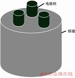
ͼ1���Խ�¯�ĵ���Ҥ����ģ��
Fig. 1��Physical model of self-jionting furnace lining electric furnace
1.1����ų�ģ��
������ų��Ļ�������ΪMaxwell�����飺
 (1)
(1)
ʽ�У� Ϊ�ų�ǿ��ʸ����A/m��
 Ϊ�ܵ����ܶ�ʸ����A/m2��
 Ϊ��ͨ�ܶ�ʸ����A/m2��tΪʱ�䣬s��
 Ϊ����������N��
 Ϊ��ͨ�ܶ�ʸ����T��
 Ϊ�糡ǿ��ʸ����V��
 Ϊ�����ܶȣ�W/m3��
1.2���¶ȳ�ģ��
����¯ϵͳ��Ҫ����缫�����غͽᾧ����ɣ�������֮������ȣ������ȴ������Ʒ��̱�ʾ
 (2)
(2)
ʽ�У���Ϊ�����ܶȣ�kg/m3��cpΪ���ϱ����ݣ�J/(kg��K)��TΪ�¶ȣ��棻��Ϊ�ȵ��ʣ�W/(m��K)����Ϊ��Ч�����ݣ�J/(kg��K)��rΪ�뾶������룬m����Ϊ�۳����ȣ�rad��ZΪ�۳ظ߶ȷ�����룬m��qΪ����Դ��J/m3��
¯���ᾧ�������̴��ȿ��Ʒ���Ϊ
 (3)
(3)
ʽ�У�keffΪ��Ч����ϵ����W/(m��K)��
���ر������߽�����Ϊ
 (4)
(4)
ʽ�У���Ϊ���ر���ڶȣ�ȡ0.8��TambΪ�����¶ȣ��棻��Ϊ�����ϵ����
������ᾧ�ڶ������ȱ߽�������
 (5)
(5)
ʽ�У�hΪ����ϵ����W/(m2��K)��TwΪ��ȴˮ�¶ȣ��档
1.3��ģ�ͼ������
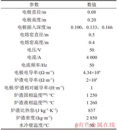
�Խ�¯�ĵ���¯ϵͳ�ľ�������������1��ʾ������ѧ�߽�����Ϊ�趨�缫���¶�Ϊ300 �棬���ر��淢����Ϊ0.8�������¶�Ϊ20 �棬�趨��ʼ����״̬ΪҺ̬���¶�Ϊ1 300 �档
��1��ģ�����ò���
Table 1��Parameters used in the model
2 ģ����
2.1����ų����¶ȳ�
�ڵ缫���������Ϊ0.133 mʱ�������е������Ÿ�Ӧ�������Ⱥ��¶ȳ��ֲ���ͼ2��ʾ����ͼ2��֪���缫��֮������ϴ������������ڵ˼�ͷ�����Ÿ�Ӧǿ�ȷֲ������ǿ�ȷֲ���Ӧ���缫�ڲ�Ÿ�Ӧǿ�Ƚϴ����·��缫�����ڵ����ܶȸ�����Ÿ�Ӧǿ�ȸ�ǿ�������н�������Ҫ������3���缫֮�䣬�������λ�ڵ缫���¶˼�ͷ������Ȼ���������¶ȳ������Ļ�������������ͼ����һ�����죬�ڽ����ȷֲ���ͼ�У������ֵ�ڵ缫���¶˼�ͷ���������¶ȳ��ֲ�������¶�ֵ�������������ģ���������Һ̬¯���������ԽϺã��缫�����������������ܹ��ܿ촫�ݳ�ȥ����ˣ������ֵ��������������3���缫��֮�䡣
�ڵ缫���������Ϊ�ֱ�Ϊ0.100��0.133��0.166 mʱ�������е��������ֱ�Ϊ321.7��264.2��193.7 kA/m2�����Ÿ�Ӧǿ�ȷֱ�Ϊ2.16��10-2��2.01��10-2��0.189��10-2 T�������е�����ȷֱ�Ϊ3.92��107��3.66��107��1.9��107 J������������¶ȷֱ�Ϊ3 260��2 680��2 312 �档���ŵ缫������������ӣ������е�����С����Ӧ�Ľ����ȷֲ�Ҳ��С�������������ӣ��������¶ȼ�ֵ���͡���������ϵͳ�е���·���ֱ�Ϊͨ���缫������ﵽ���ؼ�ͨ���缫���˵������أ�ϵͳ��Ч����Ϊ��2��·�����貢��ֵ�����ŵ缫������������ӣ�ͨ���缫����������������ӵ������ӣ�ͨ���缫�������������䣬���費�䣬��ˣ�����贮��ֵ���ӣ�ϵͳ�����ֲ���С����Ȼ�ֲ������ȼ�С���¶ȼ�ֵ���ͣ��������������ӣ��۳����¶ȸ��Ӿ��ȣ������ڵ��ʹ��̵Ľ��С���ˣ���ʵ�������У��ڱ�֤����Ч��������£������ӵ缫��������ȴӶ��������������ߵ���Ч����
��ͬ�缫����������������о�缫����0.08 m����Ҫ�����ֲ�ͼ��ͼ3��ʾ����ͼ3�ɼ����������ص����С������������ЧӦ�������е����ֲ���Ҫ�ܵ��缫����Ӱ�졣�������缫����������ϴ�������ֲ������������Ҳ࣬�ҵ缫�����·����ֵ������������ƣ��Ÿ�Ӧǿ�ȷֲ������˸��м�͵����ƣ������ڵ缫����Ӱ���ڵ缫�����·����ֶ����������ȷֲ������������Ҳ����ڵ缫���·����ֶ��������ƣ��¶ȷֲ����˵��м�ߵ����ƣ����Ų���������ӣ����صĵ�Ч�������ӣ������е����ֲ���С�������дŸ�Ӧǿ�Ƚ��ͣ��ҵ缫���·��Ÿ�Ӧǿ�ȶ������Ƽ������缫���·������ȶ������Ƽ�С���¶���֮���ͣ��缫���������ÿ����0.033 m���������Ÿ�Ӧǿ�ȡ������Ⱥ��¶ȷֱ�16.5%��6.8%��31.3%��10.3%��
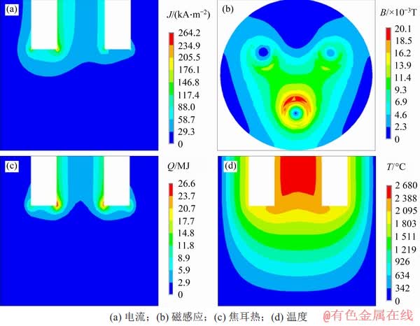
ͼ2����Ҫ�����ֲ���ͼ
Fig. 2��Distribution nephograms of main field quantities
2.2���Խ�¯�ĺ��
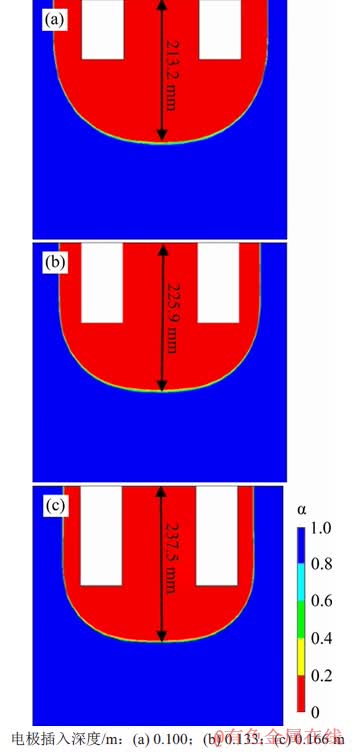
��ͬ�缫����������۳���״�������ͼ��ͼ4��ʾ����ͬ�缫����������������С�Խ�¯�ĺ�����2��ʾ����ͼ4�ͱ�2�ɼ������ŵ缫����������ӣ������۳��н����ȼ�С���Խ�¯�ĺ��������������Խ�¯�ĺ������С�Խ�¯�ĺ�Ȳ�ֵ������
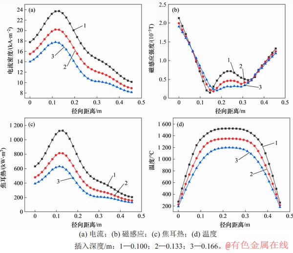
ͼ3����Ҫ�����ֲ�������
Fig. 3��Cloud curves of main field distribution
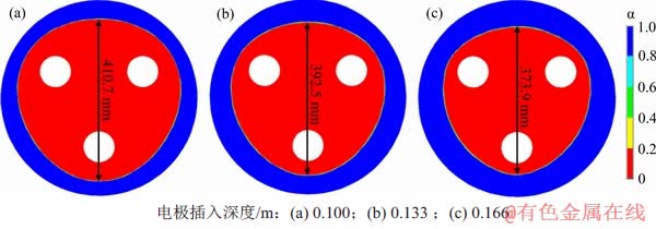
ͼ4����ͬ�缫����������۳���״�������ͼ
Fig. 4��Shapes of molten pool (cross section) at different electrode insertion depths
��2���Խ�¯�ĺ��
Table 2��Thickness of self-jointing wall

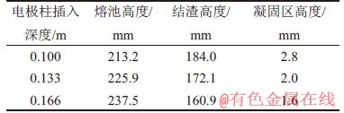
��ͬ�缫����������۳���״�ݽ�����ͼ��ͼ5��ʾ����ͼ5�ɼ����۳���״���¶ȳ���ͼ��Ӧ�����ڹ����¶���Ϊ1 250 �棬Һ���¶���Ϊ1 260 �棬�¶�����С����������Χ��С����3��ʾΪ�缫��������ȶ��۳ء������㼰�������߶ȵ�Ӱ�죬�ɱ�3�ɼ����۳ظ߶���缫����������Ӷ����ӣ������߶���缫����������Ӷ���С���������߶���缫����������Ӷ���С���۳���״ͬʱ�ܵ缫�������Ľ������Լ�ˮ����¶ȵ�Ӱ�죬���ڵ���缫��Զ���缫��Ӱ���С���¶��ݶȽϴ���ͼ5�ɼ��۳���Ƚ������������Ҫ��������Ϊ�缫���˼�ͷ�������ŵ缫������������ӣ������߶Ⱥ��������߶���С��
��3���缫��������ȶ��۳ء������㼰�������߶ȵ�Ӱ��
Table 3��Influence of insertion depth of electrode column on height of molten pool, slag and solidification zone
ͼ5����ͬ�缫����������۳���״�ݽ�����ͼ
Fig. 5��Shapes of molten pool (longitudinal section) at different electrode insertion depths
3 ����
1) ���ص���ϴ���������ЧӦ�������е���������·��Ϊ�缫������漰�缫���ˣ����е������ĵ������ڲ���������ĵ������ܵ缫��Ӱ�죬�ڵ缫���·�����ֵ����������������дŸ�Ӧǿ���������Ӧ�����ž�Բ�ľ����������������������Ӷ���С��
2) �������¶ȳ������˵��м�ߵ����ƣ�����������Ƚ��Ͷ���С�������н�����λ�ڵ缫���ڲ�˼�ͷ����������¶�λ���������ġ���������Һ̬¯���������ԽϺã�����Ч����ǿ���ڵ缫����ͷ���������������ܿ���ߡ�
3) ���ŵ缫������������ӣ������������������������ӣ�ϵͳ�ĵ�Ч�������ӣ�ϵͳ�¶ȼ�ֵ��С��ʵ�������������ӣ������ڵ��ʹ��̵Ľ��С�
�ο����ף�
[1] KANG Junfeng, CHENG Jinshu, WANG Jing, et al. Preparation and properties of CaO-MgO-Al2O3-SiO2 glass-ceramics from granite wastes[J]. Materials Science Forum, 2017, 890: 312-316.
[2] FRANCIS A, VILMINOT S. Crystallisation kinetics of mullite glass-ceramics obtained from alumina�Csilica wastes[J]. International Journal of Sustainable Engineering, 2013, 6(1): 74-81.
[3] QIN Shouwan, SHEN Jianjun, WANG Huifen, et al. Utilization of blast furnace slag, steel slag in the production of clinker[J]. Materials Science Forum, 2013, 743/744: 334-338.
[4] KHARICHA A, SCHUTZENHOFER W, LUDWIG A, et al. Influence of the slag/pool interface on the solidification in an electro-slag remelting process[J]. Materials Science Forum, 2010, 649: 229-236.
[5] ������. ����̬�������۹��̵�ų����¶ȳ����о�[D]. ����: ������ѧ������ұ��ѧԺ, 2014: 19-26.
WANG Zikun. Transient study of electromagnetic and temperature field in ESR system[D]. Shenyang: Northeastern University. School of Materials and Metallurgy, 2014: 19-26.
[6] ��־��, �ɹ���, ������, ��. ��ҵ�������۹��̵缫���������ѧģ�ͼ�Ӧ��[J]. ����, 2018,53(9): 25-29.
MIAO Zhi-qi CHENG Guo-guang LI Shijian, et al. Mathematical model of electrode immersing depth in industrial electroslag remelting process and application[J]. Iron & Steel, 2018,53(9): 25-29.
[7] WANG Qiang, HE Zhu, LI Baokuan. Modeling of magnetohydrodynamic, thermal and solidified behavior in electroslag remelting process[M]//EPD Congress 2014. Hoboken, NJ, USA: John Wiley & Sons Inc, 2014: 409-415.
[8] YU Jia, LIU Fubin, JIANG Zhouhua, et al. Numerical simulation of the dynamic formation of slag skin and heat flow distribution during the electroslag remelting process[J]. Steel Research International, 2018, 89(5): 1700481.
[9] KELKAR K M, PATANKAR S V, SRIVATSA S K, et al. Computational modeling of electroslag remelting (ESR) process used for the production of high-performance alloys[M]//Proceedings of the 2013 International Symposium on Liquid Metal Processing & Casting. Cham: Springer International Publishing, 2013: 3-12.
[10] SCHOLER A, LOTHENBACH B, WINNEFELD F, et al. Hydration of quaternary Portland cement blends containing blast-furnace slag, siliceous fly ash and limestone powder[J]. Cement and Concrete Composites, 2015, 55: 374-382.
[11] NGUYEN T C, LOGANATHAN P, NGUYEN T V, et al. Adsorptive removal of five heavy metals from water using blast furnace slag and fly ash[J]. Environmental Science and Pollution Research, 2018, 25(21): 20430-20438.
[12] REN N, LI B K, LI L M, et al. Numerical investigation on the fluid flow and heat transfer in electroslag remelting furnace with triple-electrode[J]. Ironmaking & Steelmaking, 2018, 45(2): 125-134.
[13] KARIMI-SIBAKI E, KHARICHA A, BOHACEK J, et al. On validity of axisymmetric assumption for modeling an industrial scale electroslag remelting process[J]. Advanced Engineering Materials, 2016, 18(2): 224-230.
[14] WANG Qiang, CAI Hui, PAN Liping, et al. Numerical investigation of influence of electrode immersion depth on heat transfer and fluid flow in electroslag remelting process[J]. The Journal of Minerals, Metals & Materials Society, 2016, 68(12): 3143-3149.
[15] HUANG Xuechi, LI Baokuan, LIU Zhongqiu, et al. Numerical investigation and experimental validation of motion and distribution of nonmetallic inclusions in argon protection electroslag remelting process[J]. Metals, 2018, 8(6): 392.
[16] KELKAR K M, O��CONNELL C J. A computational model of the electroslag remelting (ESR) process and its application to an industrial process for a large diameter superalloy ingot[C]//Proceedings of the 9th International Symposium on Superalloy 718 & Derivatives: Energy, Aerospace, and Industrial Applications. Cham: Springer International Publishing, 2018: 243-261.
[17] WANG Zhen, FU You, WANG Ninghui, et al. 3D numerical simulation of electrical arc furnaces for the MgO production[J]. Journal of Materials Processing Technology, 2014, 214(11): 2284-2291.
[18] KARALIS K T, KARKALOS N, CHEIMARIOS N, et al. A CFD analysis of slag properties, electrode shape and immersion depth effects on electric submerged arc furnace heating in ferronickel processing[J]. Applied Mathematical Modelling, 2016, 40(21/22): 9052-9066.
[19] GENG Xin, JIANG Zhouhua, LI Wanming, et al. Numerical simulation of thermal characteristics in the process of electroslag remelting for production of large slab ingots[J]. Journal of Iron and Steel Research(International), 2012, 19(S1): 149-152.
[20] XIE Dongsheng, Jahanshahi S, Norgate T. Dry granulation to provide a sustainable option for slag treatment[C]//Sustainable Mining Conference, Kalgoorlie, Australia. 2010: 22-28.
���༭ ��������
�ո����ڣ� 2019 -09 -06; �����ڣ� 2019 -11 -11
������Ŀ(Foundation item)�������ص��з��ƻ���Ŀ(2018YFB0605900) (Project(2018YFB0605900) supported by National Key Research & Development Program of China)
ͨ�����ߣ��ո����������ڣ�����ұ��¯Ҥģ�ͼ��Ż������о���E-mail��sfyong@ustb.edu.cn

