Trans. Nonferrous Met. Soc. China 22(2012) s566-s572
Compressive property and energy absorption characteristic of 3D open-cell Ni-Cr-Fe alloy foams under quasi-static conditions
PANG Qiu1, WU Gao-hui1, 2, SUN Dong-li1, XIU Zi-yang1, 2, ZHANG Qiang1, HU Zhi-li2, 3
1. School of Materials Science and Engineering, Harbin Institute of Technology, Harbin 150001, China;
2. State Key Laboratory of Advanced Welding and Joining, Harbin Institute of Technology, Harbin 150001, China;
3. National Key Laboratory of Precision Hot Processing of Metals, Harbin Institute of Technology, Harbin 150001, China
Received 28 August 2012; accepted 25 October 2012
Abstract: Reticulated open-cell Ni-Cr-Fe foams were manufactured by gas-phase codeposition of Cr and Fe onto the struts of pure Ni foam at 1050 ��C, and then the samples were homogenization treated at 1200 ��C in a vacuum atmosphere. The quasi-static compressive behavior and energy absorption characteristics of the Ni-Cr-Fe alloy foams with different Cr and Fe contents were discussed. The mechanical properties of these open-cell Ni-Cr-Fe alloy foams were also comparable with the pure Ni foams or the hypothetical Ni-Cr-Fe foam model. The results show that although the alloy foam struts show the similar hardness, the compressive strengths and energy absorption properties of the open-cell Ni-Cr-Fe alloy foams increase with increasing the Cr and Fe contents. The stress��strain behaviours of the Ni-Cr-Fe alloy foams are as smooth as those of nickel foams, indicating that the Ni-Cr-Fe alloy foams are the characteristic of typical ductile metallic foam. The energy absorption capabilities of the Ni-Cr-Fe alloy foams exhibit 22 times higher than that of the pure Ni foams. Simultaneously, the compressive strength of the Ni-Cr-Fe alloy foams at ambient temperature is in agreement with theoretical prediction by Gibson�CAshby model.
Key words: metallic foam; Ni foam; vapour deposition; coating; heat treatment; pack cementation
1 Introduction
Recently, there has been a considerable increasing interest in using open-cell metal foams as catalyst supports, filters, electrodes, heat exchangers, etc, because of their unique combination of high porosity, relatively high stiffness and reaction surface area [1,2]. These applications require a relatively high mechanical performance as well as elevated corrosive and oxidation resistance. However, the mechanical performance of the open-cell metal foams is found to be strongly affected by the foam characteristics like shape and size of the cells, cell wall thickness and cell connectivity. The 3D open-cell nickel-based alloy foams with uniform pore structure are attractive candidates for automotive exhaust gas purification due to their good wear resistance and durability at high temperatures [3]. However, the traditional liquid-phase methods for processing open-cell metal foams present severe challenges due to their high melting point and complicate 3D open-cell network structure [4]. When the solid-state techniques are applied to open-cell alloy foams, the shape, size, spacing and connectivity of the pores are difficult to control and the porosity achieved is much low [5].
At present, the open-cell pure nickel foams are mainly produced by electrolytic deposition method. However, the major limitation of electrolysis deposition process is that only a few metallic elements are deposition (nickel-based alloys are difficult) [6]. In addition, non-uniform deposition may occur due to the irregular shaped geometry. Currently, more interest focuses on the chemical or physical vapour deposition methods using the organic foam as the substrate. However, vapour decomposition of the least expensive chemical precursors occurs at high temperatures where the thermal stability of the polymer template must be taken into consideration [6].
The pack cementation process is an efficient and cost effective method to improve the surface properties of materials [7]. Pack-chromizing has been widely applied to steels and superalloys to improve their high temperature oxidation resistances [8,9]. Recently, HODGE and DUNAND [4] demonstrated that open-cell pure Ni foams could be pack-aluminized into homogenous NiAl foams with 28%-33% Al, but the NiAl foams were brittle at ambient temperature due to the very low toughness and ductility of NiAl.
The Ni-Cr-Fe system is an important model alloy for nickel-based alloys because of their good corrosion resistance and high strength at elevated temperatures [10]. The constitution of Ni-Cr-Fe system has been well determined in the region of 0 �C40% Fe and 20%-46% Cr [11]. Especially Inconel 690 alloy with the high chromium content is a high-performance nickel-based alloy used in corrosive and high-temperature environments [12].
In the present work, the feasibility for synthesis of the Ni-Cr-Fe alloy foams was investigated by co-deposition of Cr and Fe onto open-cell nickel foams. Based on the compositions of Inconel 690 (60% Ni, 30% Cr, 9.5% Fe, 0.03% C), a new kind of Ni-Cr-Fe single-phase austenitic, oxidation-resistant alloy foam is developed by increasing and modifying some of the alloying elements. The quasi-static compressive behaviour and energy absorption characteristic of Ni-Cr-Fe alloy foams with different Cr and Fe contents are discussed. The mechanical properties of Ni-Cr-Fe alloy foams are also comparable with the pure Ni foam and theoretical predictions for Gibson-Ashby model.
2 Experimental
2.1 Initial open-cell nickel foams
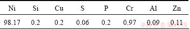
The open-cell nickel foams with porosities of 98% (20 pores per linear inch) were fabricated by electro- deposition on a polymer substrate. Then the polymer foam was removed by a suitable heat treatment. The structure of nickel foam was the quasi exact replication of the original polyurethane foam. The element compositions of the nickel foam are listed in Table 1. The SEM images of open-cell nickel foam are shown in Fig. 1, and the nickel foam was an interconnected network of solid struts or plates which formed the edges and faces of cells. The regular round shape of the nickel foam was more uniformly distributed throughout the sample compared with that of the alloy foam by the infiltrating process method [13].
Table 1 Element compositions of open-cell nickel foam (mass fraction, %)
2.2 Synthesis of open-cell Ni-Cr-Fe foams
The open-cell nickel foam was ultrasonically cleaned. The pack consisted of 5% NH4Cl, 5% Fe, 20% Cr powder (with an average particle size of 55 ��m) and 70% Al2O3 filler powder (with an average particle size of 45 ��m). A total pack mass of 125 g was poured in a stainless-steel can in which the nickel foam (with mass about 0.56 g) was embedded in the pack powder. The pack co-deposition process was carried out at 1050 ��C for 4-10 h, and then the stainless-steel was allowed to cool to room temperature.
The samples were encapsulated in evacuated quartz tubes and annealed at 1200 ��C for 12 h and 48 h. The mass gains of the samples were measured by using the BP211D analytical balance. The relative density of alloy foam was defined as the foam density divided by that of the solid material.
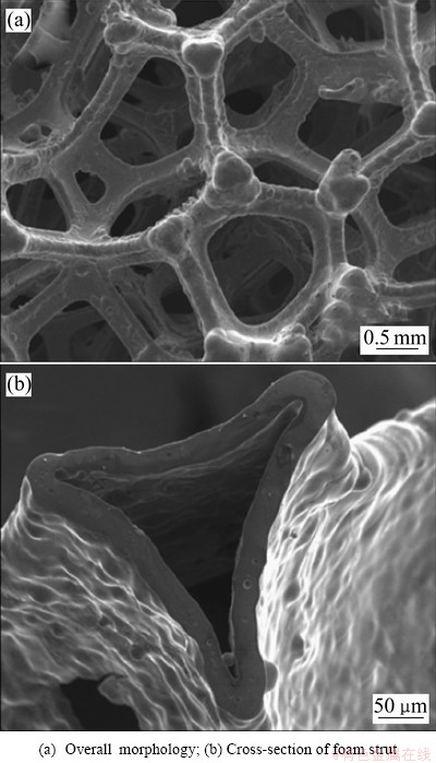
Fig. 1 SEM images of open-cell nickel foam
The phases and compositions of all alloy foams before and after homogenization were checked by energy dispersive X-ray spectroscopy (EDS). Vickers micro- hardness measurements were made in a Shimadzu micro hardness tester HMV-2000, using a force of 0.98 N and a holding time of 15 s. The quasi-static compressive tests were conducted in an Instron 5569 testing machine with a cross-head speed of 0.01 mm/s. The samples with 20 mm in diameter and 10 mm in height were compressed to 40% of their initial height and at least three experiments were conducted for each case.
3 Results and discussion
3.1 Pack cementation process
The pack cementation with NH4Cl is characterized by the following reactions. Firstly, solid NH4Cl is heated to decompose it into NH3 gas and HCl gas at 300 ��C. Then HCl will react with the Cr and Fe sources in the pack to form CrCl2 and FeCl2. When the temperature is above 600 ��C, the reduction reaction of CrCl2 and FeCl2 can be maintained. The atomic radius and electro- negativity of the Cr ions are very similar to those of the Fe atoms. The Cr and Fe ions prefer to resident in the Ni sublattice. As a result, a large number of Fe and Cr ions move into the Ni substrate layer. The corresponding reaction can be described as follows:
NH4Cl(s)=HCl(g)+NH3(g) (1)
2HCl(g)+Cr(s)=CrCl2(g)+H2(g) (2)
2HCl(g)+Fe(s)=FeCl2(g)+H2(g) (3)
Figure 2 shows a plot of the time-dependence of the Ni foam mass gain upon Cr and Fe at 1050 ��C, expressed as an average concentration. It can be seen that the Cr and Fe contents increase with increasing the deposition time and the resulted foams exhibit Cr content of 28%-35% and Fe content of 16%-22%. As compared with the pack-chromizing on the pure Ni foam [14], the co-deposition of Cr and Fe powder can promote the Cr diffusion under the same deposition condition. The result indicates that the chromizing kinetics is obviously increased with increasing the number of Fe atoms. The element compositions, relative density and geometric parameters (cell diameter, strut length, strut wall thickness) of open-cell Ni-Cr-Fe alloy foams are listed in Table 2.
3.2 Cross-sectional morphology of open-cell Ni-Cr-Fe foams
Figure 3 shows the cross-sectional SEM images and the corresponding content profiles of major elements in the Ni-(28%-34%)Cr-Fe foam struts co-deposited at 1050 ��C for 4 h and 8 h, respectively. The overall foam architecture and the hollow strut morphology are maintained after co-deposition. The element content profiles confirm that both Cr and Fe are deposited from the vapor phase and diffuse into the substrate, which leads to the formation of a uniform Cr-Fe coating layer in Fig. 3(a). The Cr-Fe coating shows fair adhesion with the nickel struts and the total thickness of the coating including the diffusion zone is about 25 ��m.
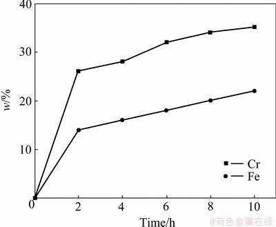
Fig. 2 Time dependence of average composition for Ni foams upon co-deposition of Cr and Fe at 1050 ��C
When the co-deposition time is extended to 8 h in Fig. 3(b), the element content profile of the foam struts differs significantly from that formed at 1050 ��C for 4 h in Fig. 3(a). The thickness of surface Cr-Fe co- deposition layer increases with increasing chromization time, which is consistent with the experimental result in Fig. 2. It can easily distinguish the presence of the Cr-Fe coating (dark color) along the perimeter of the Ni strut cross section (light color), not only on external areas directly, but also on the seemingly inaccessible ��internal�� ones in Fig. 3(b). The Cr content varied from about 40% on the surface to 20% at a depth of about 40 ��m into the coating layer. The diffusion depth of Fe in the outer layer is similar to that of Cr, indicating a simultaneous co-deposition process. The total thickness of the coating including the diffusion zone is about 40 ��m.
Table 2 Element compositions and geometric parameters of open-cell Ni-Cr-Fe foams
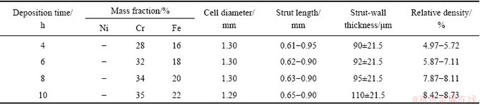
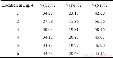
Figure 4 shows the cross-sections of Ni-34Cr-20Fe foam struts after homogenization treatment at 1200 ��C for 12 and 48 h, respectively. Table 3 presents the corresponding cross-sectional compositions of each zone on the Ni-Cr-Fe alloy foam struts. After 12 h of homogenization treatment, the existence of content gradients along the strut thickness is obvious due to localized regions of high Cr or Fe in Fig. 4(a). It can be seen that, in general, the contents of Cr and Fe in zone 2 are lower than content in Table 2. With increasing homogenization treatment time, the Cr and Fe ions can further diffuse into the Ni substrates and an opposite flux of Ni diffuses into the near-surface region. As the homogenization time is extended to 48 h, the Cr, Fe and Ni contents are approximately uniform in the foam struts (Fig. 4(b) and Table 3).
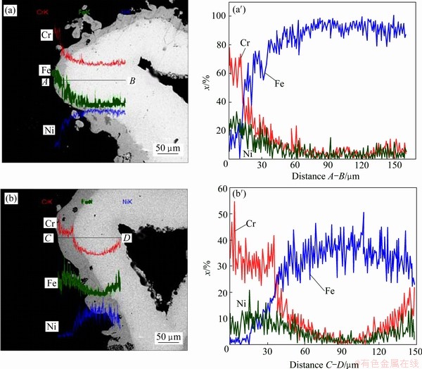
Fig. 3 Cross-sectional SEM images (a, b) and corresponding content profiles (a��, b��) of Ni-Cr-Fe foam struts after Cr-Fe co-deposition at 1050 ��C for 4 h (a, a��) and 8 h (b, b��)
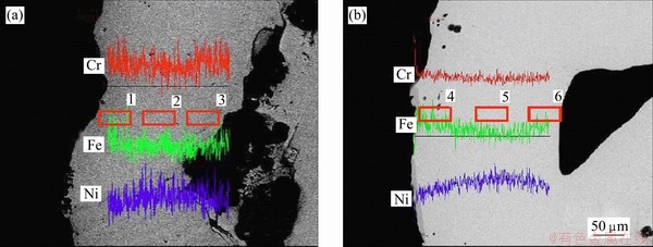
Fig. 4 SEM images of cross-sections of Ni-34Cr-20Fe foam struts after homogenization treatment at 1200 ��C for 12 h (a) and 48 h (b)
Table 3 EDS analysis of Ni-34Cr-20Fe alloy foam after heat treatment at 1200 ��C for 12 h and 48 h
3.3 Mechanical properties at ambient temperature
The results of the micro-hardness tests conducted at room temperature are summarized in Table 4. The hardness of the Ni-Cr-Fe alloy foam struts is three times higher than that of the pure Ni foams. The results confirm that the Cr and Fe elements can obviously increase the strength of the alloy foam by strengthening solid solution. Although there is a variation in element composition, the hardness of Ni-Cr-Fe alloy foam is higher than that of Ni-32Cr foam. Especially, the hardness of the Ni-35Cr-22Fe alloy foam is almost two times higher than that of the Ni-32Cr foam (HV (112��15)) [14]. The results further prove that Cr and Fe elements play a more significant role in strengthening the Ni foam strut.
Table 4 Micro-hardness of struts of open-cell Ni and Ni-Cr-Fe alloy foams
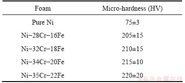
Figure 5 shows the representative compressive stress��strain curves of Ni-Cr-Fe alloy foams with different element contents compared with the pure Ni foam at the strain rate of 0.01 mm/s. It can be seen that the stress��strain curves of all foams exhibit three distinct regions [15,16]: a linear-elastic region up to approximately 5% strain, a collapse plateau region and a densification region of 25%-30% strain where the stress rises rapidly.
In this work, the compressive strength is defined as the first peak stress in the curve. It is found that the compressive strength of Ni-Cr-Fe alloy foams is one order of magnitude greater than that of pure Ni foams, because the cell wall material of the former has a higher yield stress than the latter. Simultaneously, the compressive strength of Ni-Cr-Fe alloy foam rises obviously with increasing the chromium and iron contents. Especially, the compressive strength of Ni-35Cr-22Fe alloy foam is 30 times higher than that of the pure Ni foam. The difference between peak stress and low valley stress (����) becomes higher and higher with increasing the Cr and Fe contents. The valley stress is followed by a raised stress with smooth curve, indicating that the Ni-Cr-Fe alloy foams exhibit the characteristic of typical ductile metallic foam.
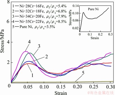
Fig. 5 Room-temperature compressive stress��strain curves of pure Ni and Ni-Cr-Fe alloy foams
For the open-cell Ni-Cr-Fe alloy foams, it is found that the compressive strength of the alloy foams is related to the yield stress of the cell wall material and the relative density of the foams. The experimental result can be descried as the Gibson-Ashby formula [17]:
 (6)
(6)
where  is the compressive strength of the foams;
  is the yield stress of cell wall material;
  is the density of the foam material;
  is the density of the massive material; C is the constant. Using values of taken from Ref. [18], the yield stress of Inconel 690 alloy is 334 MPa.
According to Eq. (6), the noticeable increase will be found in the compressive strength of open-cell Ni-Cr-Fe alloy foams when the relative density rises. The theoretical compressive strengths of Ni-Cr-Fe alloy foams are 1.1-2.5 MPa. The experimental result of Ni-Cr-Fe alloy foams is in rough agreement with that predicted by Eq. (6).
3.4 Energy absorption capacity
Energy absorption is an important technological property of foams. The energy absorption is considered the area under the stress��strain curves up to the onset of densification strain (��d). This can be expressed as [17]
 (7)
(7)
where W is the energy absorption capability and �� is the compressive stress when strain is ��.
Figure 6 shows the energy absorption capability of Ni-Cr-Fe alloy foams after homogenization in comparison with pure Ni foams, which is calculated according to Eq. (7). As seen in Fig. 6, the energy absorption capabilities of open-cell pure Ni and Ni-Cr-Fe alloy foams increase linearly with increasing the strains. The energy absorption capacity of Ni-Cr-Fe alloy foam increases by 17.5% and 31.2% when the relative density increases from 5.4% to 7.9% and 8.5% at the strain of 0.6. Especially, the Ni-35Cr-22Fe alloy foams after homogenization show the best energy- absorption characteristic in the Ni-Cr-Fe alloy foams, which is 22 times higher than that of the pure Ni foam. In comparison with another type of reinforced foam, i.e., closed cell aluminum-fly ash particle composite foam, the Ni-35Cr-22Fe foam exhibits the same as energy-absorption capability [19].
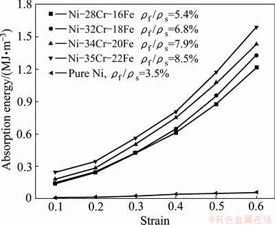
Fig. 6 Energy absorption capability of pure Ni and Ni-Cr-Fe alloy foams
4 Conclusions
1) The NH4Cl-activated packs containing elemental Cr and Fe as the deposition source are possible. The pack cementation process is adapted to the production of Ni-Cr-Fe alloy foams.
2) The open-cell Ni-Cr-Fe alloy foams can be significantly strengthened by homogenization heat treatment. Moreover, the compressive strength of Ni-Cr-Fe alloy foam rises obviously with increasing the chromium and iron contents. Especially, the compressive strength of Ni-35Cr-22Fe alloy foam is 30 times higher than that of the pure Ni foam.
3) The compressive strengths of Ni-Cr-Fe alloy foams predicted by the Gibson-Ashby theoretical model are in rough agreement with the experimental values.
4) The energy absorption capacity of Ni-Cr-Fe alloy foam increases with increasing the relative density and the strain. The Ni�C35Cr�C22Fe alloy foams after homogenization show the best energy-absorption characteristic, which is 22 times higher than that of the pure Ni foam.
References
[1] BAI M, CHUNG J N. Analytical and numerical prediction of heat transfer and pressure drop in open-cell metal foams [J]. Int J Therm Sci, 2011, 50(6): 869-880.
[2] HUO D W, YANG J, ZHOU X Y, WANG H, ZHANG T K. Preparation of open-celled aluminum foams by counter-gravity infiltration casting [J]. Transactions of Nonferrous Metals Society of China, 2012, 22(1): 85-89.
[3] BOONYONGMANEERAT Y, DUNAND D C. Ni-Mo-Cr foams processed by casting replication of sodium aluminate performs [J]. Adv Eng Mater, 2008, 10(5): 379-383.
[4] HODGE A M, DUNAND D C. Synthesis of nickel�Caluminide foams by pack-aluminization of nickel foams [J]. Intermetallics, 2001, 9(7): 581-589.
[5] LI C, WANG H, ZHOU X, LI J, LIU H. Debinding of stainless steel foam precursor with 3-D open-cell network structure [J]. Transactions of Nonferrous Metals Society of China, 2010, 20(12): 2340-2344.
[6] QUEHEILLALT D T, HASS D D, SYPECK D J, WADLEY H N G. Synthesis of open cell metal foams by templated directed vapor deposition [J]. J Mater Res, 2001, 16(4): 1028-1036.
[7] ZENG D, YANG S, XIANG Z D. Formation of hard surface layer on austenitic stainless steels via simultaneous chromising and nitriding by pack cementation process [J]. Appl Surf Sci, 2012, 258(12): 5175-5178.
[8] BAI C Y, LEE J L, WEN T M, HOU K H, WU M S, GER M D. The characteristics of chromized 1020 steel with electrical discharge machining and Ni electroplating pretreatments [J]. Appl Surf Sci, 2011, 257(8): 3529-3537.
[9] BAI C Y, WEN T M, HOU K H, GER M D. The bipolar plate of AISI 1045 steel with chromized coatings prepared by low- temperature pack cementation for proton exchange membrane fuel cell [J]. J Power Sources, 2010, 195(3): 779-786.
[10] SOPOUSEK J, VRESTFIL J. Phase-equilibria in the Fe-Cr-Ni and Fe-Cr-C systems [J]. Z Metallkd, 1994, 85(2): 111-115.
[11] UNFRIED-SILGADO J, WU L, FERREIRA F F, GARZO��N C M, RAMI��REZ A J. Stacking fault energy measurements in solid solution strengthened Ni-Cr-Fe alloys using synchrotron radiation [J]. Mater Sci Eng A, 2012, 558(15): 70-75.
[12] CHEN J H, WU W. Cavitation erosion behavior of Inconel 690 alloy [J]. Mater Sci Eng A, 2008, 489(1-2): 451-456.
[13] WANG Z H, LI Z Q, NING J G, ZHAO L M. Effect of heat treatments on the crushing behaviour and energy absorbing performance of aluminium alloy foams [J]. Mater Des, 2009, 30(4): 977-982.
[14] CHOE H, DUNAND D C. Synthesis, structure, and mechanical properties of Ni-Al and Ni-Cr-Al superalloy foams [J]. Acta Mater, 2004, 52(5): 1283-1295.
[15] PANG Q, WU G H, XIU Z Y, CHEN G Q, SUN D L. Synthesis and mechanical properties of open-cell Ni-Fe-Cr foams [J]. Mater Sci Eng A, 2012, 534(1): 699-706.
[16] YU S, LUO Y, LIU J. Effects of strain rate and SiC particle on the compressive property of SiCp/AlSi9Mg composite foams [J]. Mater Sci Eng A, 2008, 487(1-2): 394-399.
[17] GIBSON L J, ASHBY M F. Cellular solids-structure and properties [M]. 2nd ed. Cambridge, UK: Cambridge University Press, 1997.
[18] PARK I G, LEE C S, HWANG S S, KIM H P, KIM J S. Caustic stress corrosion cracking of alloys 600 and 690 with NaOH concentrations [J]. Chem Mater Sci, 2005, 11(5): 401-409.
[19] MONDAL D P, GOEL M D, DAS S. Compressive deformation and energy absorption characteristics of closed cell aluminum-fly ash particle composite foam [J]. Mater Sci Eng A, 2009, 507(1-2): 102-109.
��ά����Ni-Cr-Fe�Ͻ���ĭ����̬ѹ�����ܺ�������������
�� �� 1�����1, 2���ﶫ��1��������1, 2���� ǿ1����־��2, 3
1. ��������ҵ��ѧ ���Ͽ�ѧ�빤��ѧԺ�������� 150001��
2. ��������ҵ��ѧ �Ƚ����������ӹ����ص�ʵ���ң�������150001��
3. ��������ҵ��ѧ ���������ȼӹ����Ҽ��ص�ʵ���ң�������150001
ժ Ҫ�����ù����ĩ����1050 ��C�¶���ά��״������ĭNi�������Cr-Fe��������Ȼ��1200 ��C���¹�����ɢ�����Կ�����ĭNi-Cr-Fe���б���Ͻ��о���ͬ����������Cr��Fe������Ni-Cr-Fe�Ͻ���ĭ����̬ѹ�����ܺ������������ܡ�ͬʱ��������Ni-Cr-Fe�Ͻ���ĭ����ʵ��ѧ�����봿��ĭNi�ͼ����Ni-Cr-Fe�Ͻ���ĭģ�ͽ��бȽϡ������������ͬCr��Fe�����Ŀ���Ni-Cr-Fe�Ͻ���ĭ�Ǽ���ʾ�����Ƶ�Ӳ�ȣ������Ͽ���Ni-Cr-Fe�Ͻ���ĭ��ѹ��ǿ�Ⱥ����������������źϽ���ĭ��Cr��Fe���������Ӷ�����������Ni-Cr-Fe�Ͻ���ĭ��Ӧ����Ӧ����Ϊ�봿��ĭNi���ƣ�����Ni-Cr-Fe�Ͻ���ĭ���е������Խ�����ĭ�ı������ԡ�ͬʱ����λ�������Ni-Cr-Fe�Ͻ���ĭ�������������ֵ����ĭNi���������22����������ó���Ni-Fe-Cr�Ͻ���ĭ����������ǿ����ʵ������ǿ�ȴ���һ�¡�
�ؼ��ʣ�������ĭ����ĭNi�����������Ϳ�㣻�ȴ����������ĩ��
(Edited by LI Xiang-qun)
Foundation item: Project (51001037) supported by the National Natural Science Foundation of China; Project (HIT.NSRIF.2013003) supported by the Fundamental Research Funds for the Central Universities, China
Corresponding author: WU Gao-hui; Tel: +86-451-86402375; E-mail: wugh@hit.edu.cn; pqiuhit@126.com
DOI: 10.1016/S1003-6326(12)61762-2

