
Finite element modeling of power spinning of thin-walled shell with hoop inner rib
BAI Qian(白 倩), YANG He(杨 合), ZHAN Mei(詹 梅)
School of Materials Science and Engineering, Northwestern Polytechnical University, Xi’an 710072, China
Received 18 December 2006; accepted 13 June 2007
Abstract: A 3D elasto-plastic finite element(FE) model of power spinning of thin-walled aluminum alloy shell with hoop inner rib was established under software ABAQUS. Key technologies were dealt with reasonably. The reliability of the FE model was verified theoretically and experimentally. The forming process was simulated and studied. The distribution of the thickness and stress, and the variations of spinning force were obtained. The workpiece springback was analyzed with ABAQUS/Standard. The results show that the FE model considering elastic deformation can not only be used to analyze the workpiece springback in the complex spinning process, but also serve as a significant guide to study the local deformation mechanism and choose the reasonable parameters.
Key words: aluminum alloy; power spinning; FE model; hoop inner rib; thin-walled shell
1 Introduction
Thin-walled aluminum alloy shells with hoop inner rib have been applied increasingly with the development of aeronautic, aerospace and military industry. Power spinning, compared with other plastic forming processes, has many advantages such as energy saving, low cost and high quality. So, it is a prior process for thin-walled axisymmetric workpiece forming and plays an important role in metal precision processing fields[1-3].
At present, thin-walled aluminum alloy shell with hoop inner rib is usually manufactured by two ways. One is cutting. In this method, the material is wasted greatly, and the mechanical property is difficult to meet the requirements of products. The other way is that the traditional mandrel structure is changed and adopted in the power spinning process to realize the forming of the complicated shell. This way makes the flow line of metal distribute along the geometry of workpiece, so the strength, fatigue property and corrosion resistance of the workpiece can be improved greatly. However, the power spinning of thin-walled aluminum alloy shell with hoop inner rib is a complex forming process, which makes the deformation control difficult. So it is of great significant to study the power spinning process of thin-walled aluminum alloy shell with hoop inner rib.
Analytic method and experimental method[4] are difficult to use for studying the power spinning process of thin-walled aluminum alloy shell with hoop inner rib. However, finite element(FE) method combined with analytic method and experimental method may become an effective way to study the deformation mechanism and forming laws[5-9], and how to establish and develop the FE model is the key point for studying the complex forming process[10-12]. The rigid-plastic FE method has been used by some researchers to study the backward ball spinning process of thin-walled tubular part with longitudinal inner ribs[8-9]. However, the elastic deformation is neglected in the rigid-plastic FE analysis, so it is difficult to make an analysis of unloading, residual stress and residual strain, then the springback and the accurate thickness of the workpiece are also difficult to be obtained. Thus the model established in Ref.[8] couldn’t be used directly for the process of power spinning of thin-walled aluminum. In this work, an elasto-plastic dynamic explicit FE model of power spinning of thin-walled aluminum alloy shell with hoop inner rib was established with ABAQUS/ Explicit. Under a given situation, the distribution of the thickness and stress and the variations of the spinning force in the forming process were obtained. Then with ABAQUS/ Standard, the springback of the workpiece was analyzed. The relevant results are helpful to studying the local deformation mechanism and choosing the reasonable parameters.
2 Establishment of FE model
In the process of power spinning of thin-walled aluminum alloy shell with hoop inner rib, blank rotates synchronously with mandrel, and two rollers move along the generatrix of mandrel. The rollers press on the blank, causing local plastic deformation. During the process, contact zones of blank/roller and plastic deformation area on the blank change locally and continuously. In order to easily simulate the process under ABAQUS software environment, some simplifications and assumptions have been made in this work:
1) Blank material is homogeneous and isotropic;
2) Rollers and mandrel are rigid body; and
3) Strain rate effect and temperature effect are neglected.
A local coordinate system, which rotates with the movement of blank element, is defined for the purpose of easy analyzing the stress fields. Fig.1 shows the local coordinate system, in which 1-direction is defined as the thickness direction, 2-direction as the hoop direction, and 3-direction as the tangential direction.
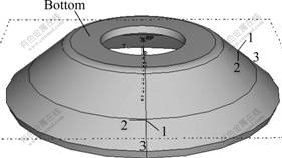
Fig.1 Local coordinate system on blank
In order to improve the computing accuracy and efficiency, some key technologies, such as contact boundary, simplification of the blank, refining the mesh and improving efficiency were adopted.
2.1 Definition of contact boundary
During the spinning process, contacts between blank and mandrel, blank and rollers are complex and dynamic. The forming process represents sliding and rolling friction behavior between blank and rollers, so coulomb friction formulation and penalty contact method were used. Between the bottom of the blank (Fig.1) and the mandrel, tie constraint is adopted to ensure that the blank rotates synchronously with the mandrel.
2.2 Simplification of blank
Deformation of the blank core is small, which has little influence on primary deformation part. But in the present research, main attention is paid on the forming process of the rib. So the core of blank is excavated to improve the computation efficiency.
2.3 Treatment of meshing
The power spinning of thin-walled aluminum alloy shell with hoop inner rib is a complex forming process with combined characteristics of bulk and sheet forming, so continuum element can describe the deformation behavior more effectively than shell element. For the blank, 3D linear reduction integration continuum element with eight nodes is used, and enhanced hourglass control is employed to ensure computing precision. In order to improve computing efficiency, mandrel is simplified as a discrete rigid part, meshed by 3D bilinear rigid quadrilateral element with four nodes, and rollers are simplified as analytic rigid parts. Some meshes of both fillets and groove of the mandrel are refined as shown in Fig.2. Because the deformation in the thickness direction of the blank is large, mesh is refined (at least 4 in the thickness direction) to reduce the mesh distortion. The flange only plays a role of rigid restriction, so sparse element is adopted in this area.
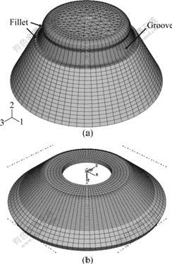
Fig.2 Meshes of mandrel (a) and blank (b)
Because of large amounts of inhomogeneous plastic deformation during the forming process, severe mesh distortion may occur, which will lead to loss of accuracy, reduction of stable time increment or even termination in simulation. In order to solve this problem, adaptive mesh technology is used. Fig.3 shows deformation cases with and without adaptive mesh technology under the same condition. Without this technology, mesh distorts in the area where thickness varies largely, while with it mesh quality is improved.
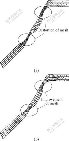
Fig.3 Comparison with and without adaptive meshing: (a) Deformation case without adaptive mesh; (b) Deformation case with adaptive mesh
2.4 Improvement of efficiency
In the FE simulation, there are two ways to improve computing efficiency: mass scaling and artificially increasing the loading velocity. The model is supposed that the strain rate is neglected, so a mass scaling factor and an acceptable artificial increase of loading velocity can be used to improve the computation efficiency.
After the key technologies are adopted reasonably, an elasto-plastic FE model of power spinning of thin-walled aluminum alloy shell with hoop inner rib is established under ABAQUS/Explicit software environ- ment as shown in Fig.4.
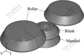
Fig.4 FE model of thin-walled aluminum alloy shell spinning with hoop inner rib
3 Verification and evaluation of model
There are two ways to evaluate the reliability of the FE model: theory evaluation and experiment verification.
Theory evaluation verifies the reliability of the model through comparing kinetic energy and artificial strain energy with internal energy. In order to indicate that the result is an acceptable quasi-static solution, there are two general criterions: 1) kinetic energy of the deformable material is less than 10% of internal energy, and artificial strain energy is less than 10% of internal energy during most of periods; 2) kinetic energy should be smooth enough.
In this work, the reliability of the model is validated by theory evaluation. The graph of energy ratios of artificial strain energy to internal energy and kinetic energy to internal energy is shown as Fig.5, which is in agreement with criterion 1. Fig.6 shows that kinetic energy increases sharply and reaches the peak value in a short time, then keeps stable, which is in agreement with criterion 2.
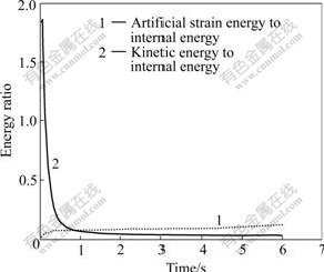
Fig.5 Energy ratio change with time
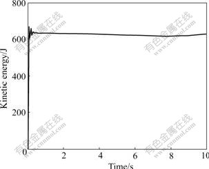
Fig.6 Kinetic energy change with time for whole model
On the other hand, with the same experimental parameters, the simulation results obtained using the above FE model are compared with the experimental results. The heights of inner rib in different roller feed rates are obtained. Fig.7 shows that the simulation results are in agreement with the experiment ones, and the maximum relative error is less than 17.8%. The discrepancy may be attributable to the simplification of the model and measuring error of the experiments. Even so, the FE model established in this work is proved to be reliable. It can be used to obtain the exact results and express reasonably the process of power spinning of thin-walled aluminum alloy shell with hoop inner rib.
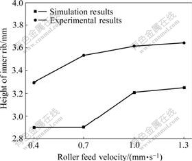
Fig.7 Results comparison of simulation with experiment
4 Model application and results
Using the FE model established above, such a spinning process is simulated and analyzed. The distribution of the thickness and stress, and the variations of spinning force are obtained. Then the springback of workpiece is analyzed with ABAQUS/Standard.
Simulation parameters used in this work are chosen according to Ref.[13], as listed in Tables 1-3. Although it is a given situation, it may provide a reference to other forming processes with different parameters.
Table 1 Main geometric parameters
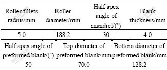
Table 2 Some material parameters
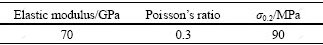
Table 3 Main processing parameters
1) Geometric parameters
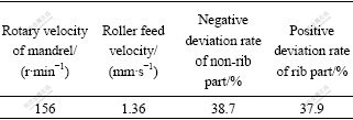
The main geometric parameters are listed in Table 1. The section of groove is trapezium, of which the height is 2.0mm; the length of top is 15.0mm, as shown in Fig.8.
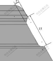
Fig.8 Section of mandrel groove (Unit: mm)
The preformed blank can be obtained by stamping or conventional spinning.
2) Material parameters
The blank material is LF2M, of which some material parameters are listed in Table 2. The stress―strain curve of the material is obtained by the tensile test, as shown in Fig.9.
Fig.9 Stress―strain curve of LF2M
3) Processing parameters
The main processing parameters are listed in Table 3. The friction coefficient is obtained by ring upsetting experiment. Friction coefficient between rollers and blank is 0.02 and the assumption that there is no friction between blank and mandrel is made.
4.1 Distribution of thickness
The section view of workpiece is illustrated in Fig.10. The axis of mandrel is defined as X-axis, the center of blank as origin (O point), the X-coordinate of each inside surface node as abscissa, and the thickness of each corresponding node as ordinate, then the thickness distribution along the X direction is obtained. As shown in Fig.11, segments A and C represent the areas near rib, while segment B represents rib area. The deformation results of segments A, B and C are as follows.
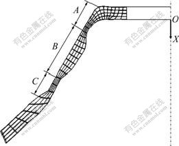
Fig.10 Mesh of formed rib
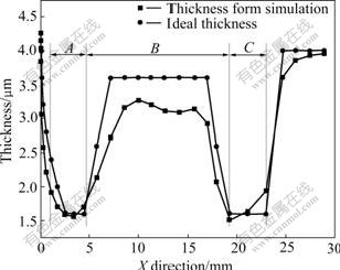
Fig.11 Distribution of thickness in X direction
1) In segment A, thickness from simulation is appreciably smaller than ideal one. This is because that the rollers apply compressive stress onto the unformed part; meanwhile, tensile stress onto the metal in segment A after the deformation of segment A is finished.
2) In segment B, thickness from simulation is much smaller than ideal one, and the maximum relative error reaches 24% in fillet near the bottom of the blank. This is because that there is not enough spinning force component to make metal fill in the fillet. According to the minimum resistance criterion of metal flow, the undeformed part has free end, and the resistance of metal flowing forward is smaller than that of flowing into the groove, so metal flows forward rather than forms the rib. After the rib is formed, with the increasing of deformation, radial tensile stress appears in the rib part, which makes the thickness decrease.
3) In segment C, the thinnest part is the adjacent area to segments B and C. This is because that metal in front of rollers cumulates severely with the development of the process. So it is difficult for metal to flow forwards, which makes metal behind the rollers elongate.
These results above show that segment B is difficult to be filled, and thickness in segment C may easily become excessively thin. So more attentions should be paid on these areas, and the groove geometry parameters and processing parameters should be optimized based on the FE model in the further research.
4.2 Distribution of stress
To conveniently study the distribution law of stress, the process is divided into 3 stages: stage 1 is the period before the rib is formed; during stage 2, rib part is being formed, and during stage 3, the rest part of workpiece is being formed. The demarcation points of three stages are 30% and 70% of process respectively. The distribution of equivalent stress in outside blank is shown in Fig.12. At stage 1, large stress of the blank appears in discontinuous girdle zone where rollers contact. At stage 2, large stress areas appear in the roller contacting area(RCA) and the deformed area near the bottom. At stage 3, large stress appears in the RCAs and fillet area. The maximum equivalent stress of stage 1 increases with the time increasing. On the contrary, the stress decreases when rib is formed (stage 2). That’s because the deviation ratio in the rib area is positive, and the deformation of the rib area is smaller than that of other areas. At stage 3, the deviation ratio is negative, so the stress increases with time increasing.
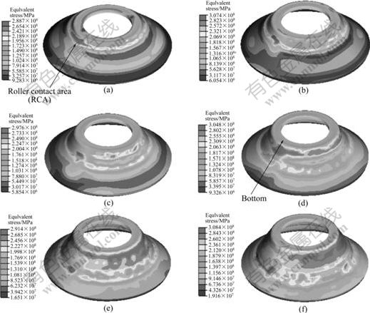
Fig.12 Distribution of equivalent stress of blank at different forming stages: (a) 15%; (b) 30%; (c) 50%; (d) 70%; (e) 85%; (f) 100%
The distributions of stress components during the forming process are shown in Figs.13-15. Because the deformation is restricted by the surrounding metal and rollers, the metal in RCAs is in a 3D compressive stress state. Material deformation behaviors of the whole workpiece in each direction are illustrated as follows.
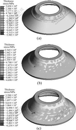
Fig.13 Distribution of thickness stress of blank at different forming stages: (a) 30%; (b) 70%; (c) 100%
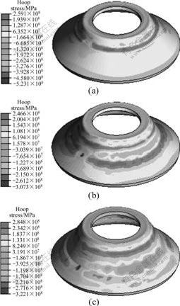
Fig.14 Distribution of hoop stress of blank at different forming stages: (a) 30%; (b) 70%; (c) 100%
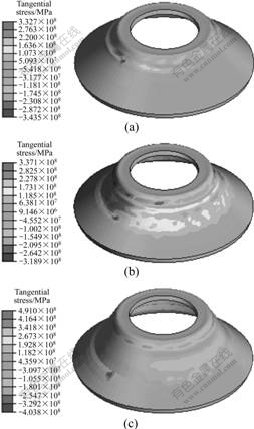
Fig.15 Distribution of tangential stress of blank at different forming stages: (a) 30%; (b) 70%; (c) 100%
In the thickness direction (as shown in Fig.13), the stress of the RCAs is always compressive. At stage 1, tensile girdle occurs in deformed blank. With the process of deformation, the tensile stress of most area gradually diminishes due to the unloading effect, except area around the RCAs.
In the hoop direction (as shown in Fig.14), at stage 1, hoop compression stress appears in the RCAs. Tensile stress appears in the roller contacting girdle zone, and metal around rollers becomes longer in the hoop direction. At stage 2, two fillets of groove prevent the metal flow, so tensile stress appears in these areas. At stage 3, hoop tensile stress occurs in the areas around rollers and the fillet near the bottom of workpiece, and the value increases gradually.
In the tangential direction (as shown in Fig.15), at stage 1, tensile stress appears in the deformed area behind the rollers, while compressive stress in front of rollers. At stage 2, compressive stress appears in the area around the groove fillet near the bottom of workpiece, and at stage 3, stress in this area is also compressive.
4.3 Variation of spinning force
In order to provide an effective guide for equipment selection, the distribution law of spinning force is studied based on the model established above. Three force components of rollers are obtained based on the spinning numerical simulation. Fig.16 shows that axial force and radial force vary severely during the forming process, and the hoop force is smaller and varies slightly. It can be found that the axial force is bigger than radial force and radial force than hoop force at any time of the forming process, which is in good agreement with experiment results from Refs.[14-15]. As shown in Fig.16, during stage1, spinning force increases gradually because of the negative deviation ratio of spinning. During stage 2, axis force and radial force decrease obviously, which is because deviation rate becomes positive in the rib part. During stage 3, metal accumulation in front of rollers prevents metal flowing, so each force component increases obviously.
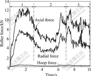
Fig.16 Change of force components with time
4.4 Springback analysis
In the forming process of thin-walled aluminum alloy shell with hoop inner rib, springback is one of the significant factors in the mandrel design and has a great influence on the final shape of workpiece. So, it is important to study the springback for the precise forming. By using static implicit algorithm, ABAQUS/Standard may calculate the springback process and obtain the springback results. In this work, after the forming process is simulated with ABAQUS/explicit, the springback results of the deformed workpiece are obtained with ABAQUS/Standard. As shown in Fig.17, the distribution of residual stress after springback is more homogeneous. This is because the springback is a process of stress self-balance. As a continuous whole, not only the RCAs undergo unloading effect, but also the rest of the workpiece after the rollers and the mandrel are moved away. The change of half apex angle is used to express the amount of springback. The average half angle before springback is 31.6?, while after springback it is 33.4?. It is found that the springback process can not be neglected after the spinning process, and the model may provide a reasonable aid for designing mandrel.
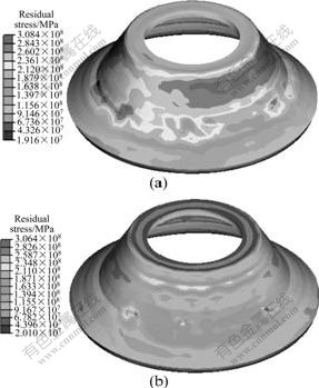
Fig.17 Distribution of residual stress before springback (a) and after springback (b)
5 Conclusions
1) An elasto-plastic analysis FE model of power spinning of thin-walled aluminum alloy shell with hoop inner rib is established under the ABAQUS/Explicit, and the key technologies involved in modeling are dealt with reasonably, including contact boundary, simplification of the blank, refining mesh and the tips to improve the efficiency in computation.
2) Based on the FE model, the given spinning process is simulated. The distribution of thickness and stress, and the variations of spinning force in forming process are acquired. The springback of workpiece is analyzed with the ABAQUS/Standard.
3) The FE model considering elastic deformation can not only be used to analyze the workpiece springback in the complex spinning process, but also serve as a significant guide to study the local deformation mechanism and choose the reasonable parameters.
References
[1] QUIGLEY E, MONAGHAN J. Metal forming: An analysis of spinning processes [J]. Journal of Materials Processing Technology, 2000, 103: 114-119.
[2] WONG C C, DEAN T A, LIN J. A review of spinning, shear forming and flow forming processes [J]. International Journal of Machine Tools & Manufacture, 2003, 43: 1419-1435.
[3] RAJNISH PRAKASH, SINGHAL R P. Shear spinning technology for manufacture of long thin wall tubes of small bore [J]. Journal of Material Processing Technology, 1995, 54: 186-192.
[4] AKKUS N, KAWAHARA M. An experimental and analytical study on dome forming of seamless Al tube by spinning process [J]. Journal of Materials Processing Technology, 2006, 173: 145-150.
[5] XIA Q X, CHENG X Q, HU Y, RUAN F. Finite element simulation and experimental investigation on the forming forces of 3D non-axisymmetrical tubes spinning [J]. International Journal of Mechanical Sciences, 2006, 48: 726-735.
[6] LIU Jian-hua, YANG He, LI Yu-qiang. A study of stress and strain distribution of first-pass conventional spinning under different roller traces [J]. Journal of Materials Processing Technology, 2002, 129: 326-329.
[7] XUE Ke-min, L? Yan. Elastic-plastic FEM analysis and experimental study of diametral growth in tube spinning [J]. Journal of Materials Processing Technology, 1997, 69: 172-175.
[8] JIANG Shu-yong. Analysis and simulation of ball spinning forming of thin-walled tubular part with longitudinal inner ribs [D]. Harbin: Harbin Institute of Technology, 2005. (in Chinese)
[9] JIANG Shu-yong, XUE Ke-min, ZONG Ying-ying, YU Lin. Process factors influencing spinning deformation of thin-walled tubular part with longitudinal inner ribs [J]. Trans Nonferrous Met Soc China, 2004, 14(4): 702-707.
[10] YANG He, GU Rui-jie, ZHAN Mei, LI Heng. Effect of frictions on cross section quality of thin-walled tube NC bending [J]. Trans Nonferrous Met Soc China, 2006, 16(4): 878-886.
[11] ZHAN M, YANG H, ZHANG J H, XU Y L, MA F. 3D FEM analysis of influence of roller feed rate on forming force and quality of cone spinning [J]. J Mater Process Tech, 2007, 187/188: 486-491.
[12] YANG He, ZHAN Mei, LIU Yu-li. A 3-D rigid-viscoplastic FEM simulation of isothermal precision forging of blade with a damper platform [J]. Journal of Materials Processing Technology, 2002, 122: 45-50.
[13] WANG Cheng-he, LIU Ke-zhang. Spinning technology [M]. Beijing: China Machine Press, 1986. (in Chinese)
[14] CHEN M D, HSU R Q, FUH K H. An analysis of force distribution in shear spinning of cone [J]. International Journal of Mechanical Sciences, 2005, 47: 902-921.
[15] CHEN M D, HSU R Q, FUH K H. Forecast of shear spinning force and surface roughness of spun cones by employing regression analysis [J]. International Journal of Machine Tools & Manufacture, 2001, 41: 1721-1734.
Foundation item: Projects(50405039; 50575186) supported by the National Natural Science Foundation of China; Project(50225518) supported by the National Science Foundation of China for Distinguished Young Scholars
Corresponding author: YANG He; Tel: +86-29-88495632; Fax: +86-29-88495632; E-mail: yanghe@nwpu.edu.cn
(Edited by LI Xiang-qun)

