Numerical simulatim of rainwater accumulation and flow characteristics over windshield of high-speed trains
��Դ�ڿ������ϴ�ѧѧ��(Ӣ�İ�)2020���1��
�������ߣ������� �Ž� ��ϰ�� ��� �����
����ҳ�룺198 - 209
Key words��high-speed train; windshield; rainwater accumulation; aerodynamic characteristics
Abstract: In this paper, a Euler-Lagrangian particle/fluid film/VOF coupled multiphase flow model is presented. Numerical simulations are conducted, and the rainwater accumulation and flow characteristics over two types of windshields are studied based on the presented model. The results show that an uneven water film is formed over the windshield, with rain water accumulation occurring for the concave windshield but not for the convex windshield. At low speeds, the average fluid-film thickness for a concave windshield is larger than that of a convex windshield; however, a minor difference occurs between these two values at high speeds, and a critical velocity is observed for the two types of windshields. When the train velocity is less than the critical velocity, the fluid film at the lower part of the windshield and the train nose flows downward, and beyond the critical velocity, the fluid film over the entire windshield and train nose flows upward.
Cite this article as: DU Jian, LIANG Xi-feng, LI Gui-bo, TIAN Hong-lei, YANG Ming-zhi. Numerical simulation of rainwater accumulation and flow characteristics over windshield of high-speed trains [J]. Journal of Central South University, 2020, 27(1): 198-209. DOI: https://doi.org/10.1007/s11771-020-4288-z.

J. Cent. South Univ. (2020) 27: 198-209
DOI: https://doi.org/10.1007/s11771-020-4288-z

DU Jian(�Ž�)1, 2, LIANG Xi-feng(��ϰ��)1, 3, LI Gui-bo(���)2,TIAN Hong-lei(�����)2, YANG Ming-zhi(������)1
1. Key Laboratory of Traffic Safety on Track of the Ministry of Education, Changsha 410075, China;
2. China Railway Rolling Stock Corporation Qingdao Sifang Co., Ltd., Qingdao 266111, China;
3. National & Local Joint Engineering Research Center of Safety Technology for Rail Vehicle,Changsha 410075, China
 Central South University Press and Springer-Verlag GmbH Germany, part of Springer Nature 2020
Abstract: In this paper, a Euler-Lagrangian particle/fluid film/VOF coupled multiphase flow model is presented. Numerical simulations are conducted, and the rainwater accumulation and flow characteristics over two types of windshields are studied based on the presented model. The results show that an uneven water film is formed over the windshield, with rain water accumulation occurring for the concave windshield but not for the convex windshield. At low speeds, the average fluid-film thickness for a concave windshield is larger than that of a convex windshield; however, a minor difference occurs between these two values at high speeds, and a critical velocity is observed for the two types of windshields. When the train velocity is less than the critical velocity, the fluid film at the lower part of the windshield and the train nose flows downward, and beyond the critical velocity, the fluid film over the entire windshield and train nose flows upward.
Key words: high-speed train; windshield; rainwater accumulation; aerodynamic characteristics
Cite this article as: DU Jian, LIANG Xi-feng, LI Gui-bo, TIAN Hong-lei, YANG Ming-zhi. Numerical simulation of rainwater accumulation and flow characteristics over windshield of high-speed trains [J]. Journal of Central South University, 2020, 27(1): 198-209. DOI: https://doi.org/10.1007/s11771-020-4288-z.
1 Introduction
With the continuous improvement of high-speed trains, their operating range has been expanding, and the geographical environment along the railway and the operating conditions of these trains are becoming increasingly complex. When high-speed trains run under extreme weather conditions, such as strong wind, heavy rain and heavy snow, the overall aerodynamic performance of the train and the functionality of key components will change greatly. To ensure the safety, reliability and passenger comfort of high-speed trains running under various operating conditions, researches on the multiphase flows of high-speed trains have attracted increasing attention.
Studies on impact of rainfall on vehicles were first performed in the aviation field and primarily included experimental and analytical studies. Rainfall can cause severe aerodynamic penalties to the wings when airplanes encounter rain during flight, and heavy rain is considered the main cause of many aviation accidents [1]. Raindrops can accumulate on the surface of wings and cause the formation of an uneven water film, which can effectively roughen the wings and change the pressure distribution. RHODE [2] first studied the effect of heavy rain on the performance of aircraft and concluded that the added drag force exacted the greatest performance penalty, although it did not appear to be a safety concern. However, later studies [3, 4] showed that heavy rain causes a reduction in the lift coefficient at most angles of attack by up to 30%.
With the development of computer technology, numerical simulation method has become the main method for studying multiphase flows. Numerical simulation of traditional gas-liquid two-phase flows involves interface tracking or interface capturing to resolve the liquid-gas interface [5, 6]; in such simulation, the Level Set method, the volume of fluid method and the moment of fluid method [7-9] are widely used. However, these methods cannot be used for rainfall simulation because of the computational complexity and computational resource limitations. To maintain a moderate numerical effort, the liquid-gas interface is not resolved, and two types of multiphase flow models suitable for simulating rainfall processes have been developed: the Euler-Euler model and the Euler-Lagrangian model. For the Euler-Euler model [10], each phase is treated as a continuous medium that may interpenetrate with other phases and described by a set of equations with regard to momentum, continuity, and energy in the Eulerian coordinate system. This model, mainly applied to cases in which the discrete phase concentration is relatively high, has been widely used because of its small computational costs. The Euler-Lagrangian model treats raindrops in the air as Lagrangian particles. The continuous air phase is solved using the Eulerian method, and raindrops are tracked using the Lagrangian method. The air phase and raindrops are one-way or two-way coupled through the model. Tracking many particles is computationally inefficient. The discrete particle model proposed by CROWE et al [11] is a form of the Euler-Lagrangian model.
Numerical simulations of the rainfall effect on high-speed trains are still at the initial stage; thus, few relevant research works are available. SHAO et al [12] used the Euler-Euler model to simulate the aerodynamic characteristics of high-speed trains under heavy rain and strong crosswinds, and their study found that the lift force, side force, and rolling moment of the train increased significantly, because of the heavy rain and crosswinds. Furthermore, based on the theory of train overturning, the safe speed limit of a train under different rain and wind levels was studied. JING et al [13] studied the combined effects of wind and rain for high-speed trains using the Euler- Lagrangian model and found that the lift force, side force and rolling moment of the train increased as the vehicle speed, wind speed and rainfall intensity increased. Because the Lagrange model can track the raindrop trajectory, the distribution of raindrops on the windward and leeward sides of the train was also given. WAN [14] and CUI [15] used the commercial software FLUENT and open-source software OpenFOAM, respectively, to calculate the velocity field and the pressure distribution around high-speed trains under different weather conditions. The Euler-Euler model was employed in their simulation, and their conclusions were consistent with those in Refs. [12, 13].
This article assumes that all raindrops are small spheres and interactions do not occur between raindrops. Raindrops will break into smaller droplets when the diameter exceeds the range of 6-7 mm, and most raindrops have a diameter of less than 2 mm [16]. The surface tension of small raindrops plays an important role in keeping raindrops approximately spherical. The second assumption has been proven by BILANIN [17]. He showed that even for extremely high rainfall levels of 1872 mm/h, for an average raindrop of 4 mm, the mean distance between raindrops will be on the order of 70 mm, i.e., 17.5 times the droplet diameter. Therefore, we can neglect raindrop collisions in our model.
The above research studies on the multiphase flows of high-speed trains were all based on whole vehicles, and most of them focused on only changes in the aerodynamic forces. However, for actual trains running in heavy rain, rainwater may accumulate near the windshield and cause an uneven water film to flow over the windshield. Extremely heavy rainfall will lead to complete failure of the windshield wipers, thereby reducing visibility and seriously affecting the driver��s vision. Although the Euler-Euler and Euler-Lagrangian models can simulate both the accumulation of raindrops at the wall and the aerodynamic changes, they cannot predict the flow behavior of the water film formed by raindrops. Few studies focus on the flow stream problem over a windshield. In this paper, we construct an Euler-Lagrangian/fluid film/VOF coupled multiphase flow model using Star-CCM+, and investigate the accumulation and flow characteristics of rainwater over a windshield. For the newly developed model, a two-way coupled Euler-Lagrangian approach is used to simulate the flow field around the train and the dynamic behavior of raindrops. The unsteady incompressible Navier-Stokes equations for the continuous phase and the Lagrangian equations of motion for the discrete phase are solved alternately and coupled by an interphase momentum exchange term. A water film is formed via the impingement from Lagrangian raindrops at the wall. The fluid-film model is adopted to predict the formation of the water film and its flow behavior over the windshield. In certain local areas, a water film can accumulate, and the VOF model will be used when the thickness of the water film exceeds a certain value. The film-VOF interaction model controls the interaction between the fluid-film phase and the VOF phase. Finally, a VOF-Lagrangian interaction model is used to consider the transition between the VOF phase and the Lagrangian phase. Using the newly developed model, an uneven water film over the windshield is observed, and its flow characteristics at different operating conditions are determined. The research results can provide reference data for the design and optimization of high-speed train heads and windshields.
2 Euler-Lagrangian/fluid-film/VOF coupled multiphase flow model
Studies on rainwater accumulation and flow over high-speed train windshields present difficulties in the following two aspects: the spatial scale of raindrops and trains differs by several orders of magnitude, and thus, it is a multi-scale problem. Meanwhile, the accumulation of rainwater with air flow over the windshield is a multiphase flow problem. At present, the Euler-Lagrangian model can handle multi-scale problems very well. For numerical simulations of multiphase flows, interface tracking methods, such as the classic level-set method, are widely used. To capture the fluid film, which is typically on the order of 1 mm thickness, the number of grid cells required for the numerical simulation is very large. Under current computer resource limitations, using the interface tracking method for engineering simulations is nearly impossible.
In this paper, the Euler-Lagrangian model, the VOF multiphase flow model and the fluid-film model are coupled together using Star-CCM+ to establish a multiphase simulation model for the problem. To be specific, the Euler-Lagrangian model is responsible for the computation of air flow, as well as the interaction between airflow and raindrops. After the raindrops hit and accumulate on the train surface, the fluid-film model is applied to compute the motion of the thin layer of rainwater, and the VOF multiphase model tracks the deformation of the interface between air and rainwater film. Thus, the entire process can be simulated, including the air flow and rain fall, as well as the accumulation and flow of rainwater on train surface.
The maximum speed of the studied train is 100 m/s, corresponding to the Mach number less than 0.3. Thus, we selected the incompressible Reynolds-averaged Navier-Stokes (RANS) equations as the continuous phase governing equations. An implicit unsteady model is used because the flow behavior of the water film has unsteady characteristics. The segregated flow model is selected using Star-CCM+, and a pressure- correction equation is solved to decouple the velocity and pressure. The governing equations are written as follows:
 (1)
(1)
 (2)
(2)
where �� is the density;  and p are the mean velocity and pressure, respectively; I is the identity tensor; T and Tt are the viscous stress tensor and Reynolds stress tensor, respectively; and g is the acceleration of gravity. The Reynolds stress tensor Tt is modeled by the eddy viscosity model, and a turbulent eddy viscosity ��t is introduced.
 (3)
(3)
where S is the mean strain rate tensor. The ��-�� SST turbulence model is added to model the turbulent effect ��t.
Considering that most raindrops are small droplets with a spherical shape, an effective simulation method for the rainfall process is to model raindrops instead of explicitly capturing their interface changes. The Lagrangian method is used in conjunction with the Eulerian method to describe the evolution of individual particles as they traverse the domain. The equation of momentum conservation for a particle is written in the Lagrangian framework:
 (4)
(4)
where mp is the mass of the particle; ��p is the particle velocity; Fs represents the forces that act on the surface of the particle and Fbrepresents the body forces. The two-way coupling between Lagrangian particles and the Eulerian continuous phase is achieved by Fs.
The fluid-film model, which is illustrated in Figure 1, is adopted to solve the flow of a thin fluid film on a surface in Star-CCM+. In this study, the fluid film over the windshield is formed via impingement from the raindrops. The behavior of the fluid film is governed by the conservation equations of mass, momentum and energy. For example, the mass conservation equation can be written as follows:
 (5)
(5)
where ��f is the film density; ��f is the film velocity; Sm is the mass source or sink from droplet impingement or film stripping per unit area; hf is the film thickness; and volume V and surface A are functions of the film thickness. For details of the fluid film governing equations, please refer to Ref. [18].
The fluid-film model is valid only in the first layer of the computational grid near the wall. The thickness of the fluid film increases gradually as the raindrops accumulate. When the film thickness increases to a certain extent, the fluid film will be transformed into the VOF interface as shown in Figure 2. This process is achieved by the fluid-film/ VOF-coupling model. In Figure 2, ��h is the height of the first layer of the computational grid near the wall. Both the fluid film and VOF can occupy a cell at the same time. If the total thickness of the liquid film and VOF is more than 0.5��h, then the fluid film transitions into the VOF. In contrast, if the total thickness of the fluid film and VOF is less than 0.5��h, then the VOF transitions into a fluid film. The transition between the fluid film and the VOF allows us to use a sparser grid, which significantly reduces the computational complexity.
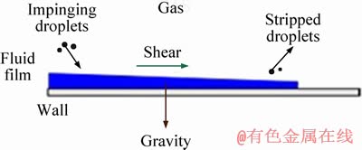
Figure 1 Fluid-film model
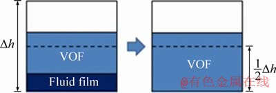
Figure 2 Fluid film transitions into VOF
The computational process for this study is as follows. First, the raindrops are introduced into the computational domain through the injector in the form of Lagrangian particles. The fluid solver calculates the continuous air flow field, and the Lagrangian model calculates the air resistance of the raindrops. The Lagrangian model takes the initial state of the raindrops and the drag force acting on them as inputs and calculates the position and tracks the trajectory of the raindrops. It is assumed that the raindrops remain spherical during traveling in air. Moreover, the reaction of raindrops to air is also considered in the model, and two-way coupling between air and raindrops is achieved. Next, the raindrops hit the surface of the train and a water film is formed. Thereafter, the raindrops are absorbed by the water film and the momentum and energy are also transferred to the water film. The coefficient of surface tension of water on the train surface is set to be 0.072 N/m. The flow behaviors of the water film are simulated by solving the fluid-film conservation equations. When the thickness of the water film exceeds a certain value, the water film will be converted to a VOF interface and governed by the VOF model.
3 Computational model setup
According to the two typical shapes of the existing driver cabin windshield, we select two different head models for our simulation as shown in Figure 3. EMU1 has a concave windshield, and EMU2 has a convex windshield. The sizes of these two head models are quite similar at approximately 9 m in length and 3.8 m in height. Bogies are not included for these two models because we consider only the flow condition near the windshield.
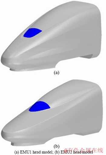
Figure 3 Two different high-speed train heads:
The computational domain is illustrated in Figure 4. The length of the domain is 60 m, and the height is 16 m. To reduce the computation time, we consider only the semi-model. Plane ABGE is a symmetry boundary; plane ABDC is the velocity inlet; plane BDHG and the train surface are non-slip walls; plane EFHG is the flow split outlet; and the other planes are slip wall boundaries that present speeds equal to the flow velocity. The computational domain is discretized using the Trimmed Cell Mesher provided by Star-CCM+, and two prism layers are generated. The thickness of the first boundary layer is 2 mm, and the averaged y+ is approximately 50. y+ defined in formula (6) is a dimensionless value, which is used to estimate the first layer��s height of mesh near the train surface ����
 (6)
(6)
where y is the distance from the wall, ��t is turbulent eddy viscosity, u is the kinematic viscosity.
Figure 5 shows the mesh distribution on the symmetry plane. We can see that the mesh near the wall is relatively dense compared to that far from the wall. Test of the mesh convergence will be presented in the next section.
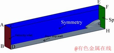
Figure 4 Computational domain
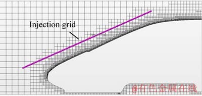
Figure 5 Mesh on symmetry plane and injection grid
The segregated flow modeling platform Star-CCM+ is chosen to solve the incompressible Navier-Stokes equations. Both the convective and viscous terms are discretized by schemes with second-order accuracy. The time is discretized by the implicit unsteady model with first-order accuracy, and the time step is set to 0.001 s. The computational model must track the trajectory of the raindrops, which is a time-consuming task when the number of raindrops is large. To further reduce the computation time, an injection grid is created in front of the train head, and the raindrops are injected into the computational domain through the grid nodes, as shown in Figures 5 and 6. The initial horizontal velocity of the injected raindrops remains the same as the inlet velocity, and the vertical velocity is the falling velocity of real raindrops. The velocity magnitude of the raindrops follows a normal distribution, and the deviation is 3 m/s. The flow rate of the injection grid can also be defined to simulate the rainfall rate. By adjusting the resolution of the injection grid, the raindrops can be uniformly sprayed onto the train. Figure 6 shows the movement and distribution of raindrops for EMU2 at the speed of 30 m/s. The green part represents the injection grid, which has a resolution of 120��104.
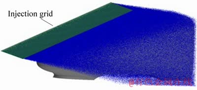
Figure 6 Raindrop distribution for EMU2 at 30 m/s
4 Results and discussion
4.1 Mesh sensitivity
To test the mesh sensitivity, four sets of mesh with different meshing densities on EMU1 were generated as shown in Figure 7. Detailed mesh information is presented in Table 1. Note that the first layer thickness of all meshes remain identical (2 mm) for ensuring that the wall y+ values are the same during mesh sensitivity tests.
Numerical tests on the four meshes are conducted with EMU1 at speed of 100 m/s. As the current research focuses on the rainwater distribution over the train windshield, the averaged fluid-film thickness on the windshield is chosen to evaluate the sensitivity of numerical results with different meshes. As shown in Table 1, the thickness of the fluid-film slightly decreases with the increase of mesh density. However, the difference of numerical results is negligible for mesh 2, mesh 3 and mesh 4. Thus, mesh 3 is adopted for the numerical study presented next.
4.2 Rainwater collection in a bowl
The purpose of this test case is to determine the validity of the proposed Euler-Lagrangian/ fluid-film/ VOF coupled multiphase flow model. A bowl with a hemispherical shape is placed in the rain (Figure 8(a)), and the diameter of the bowl is 100 mm. We assume that there is no crosswind, and all raindrops move in the vertical direction. The raindrop diameter and falling speed are 2 mm and 6 m/s, respectively. All raindrops are introduced into the computational domain by a round injector as shown in Figure 8(b). The volume flow rate of the raindrops injector is 1.3��10-5 m3/s, which can be used to calculate the injection frequency.Figure 8(c) shows the trimmed cell mesh with two boundary layers generated in Star-CCM+. The thickness of the first boundary layer mesh is 1 mm.
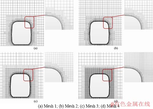
Figure 7 Meshes with different meshing sizes for sensitivity test:
Table 1 Mesh information for mesh sensitivity test
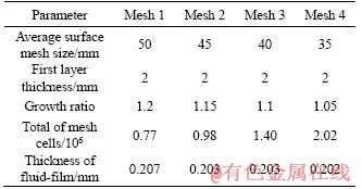
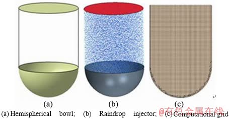
Figure 8 Rainwater collection in a bowl:
We use the unsteady state laminar flow model because the flow velocity is not high, and the time step is set to 0.001 s [19, 20].
Figures 9(a) and (b) show the water-air interface and the water film over the bowl surface at the time of 5.167 s. Rainwater gathers at the bottom of the bowl via gravity, and the water-air interface is captured by the VOF model. As shown in Figure 9(a), a water film is formed over the bowl surface that has not been covered by rainwater. The thickness of the water film increases when approaching the interface. The maximum water film thickness is approximately 0.2 mm. The water depth H in Figure 9(b) is approximately 22.4 mm, and the volume of rainwater is approximately 6.7046��10-5 m3. The volume of rainwater calculated from the injection rate and time is 6.7171��10-5 m3, which is very close to the simulated value, thus indicating that the proposed Euler-Lagrangian/fluid-film/VOF coupled
multiphase flow model is accurate.
4.3 Rainwater accumulation over a high-speed train windshield
In this study, the rainfall rate (rainfall intensity per hour) is set as 100 mm/h, which is chosen as the medium intensity of heavy rains. Accordingly, the raindrops are assumed to be small spheres with diameter of 2 mm. The mean falling velocity of raindrops is set to be 5 m/s, which approximately is the terminal velocity of raindrops in that size. To investigate the influence of train speed on the accumulation and flow behavior of rainwater, simulations are conducted with train speeds ranging from 30 to 100 m/s. The total computational time is 60 s, after which the distribution of rain-film reaches the quasi-steady state judging by the change of film thickness. This yields in the total time step of 60000 with the time interval size being 0.001 s. Thus, all the results shown below are the final state of numerical simulations.
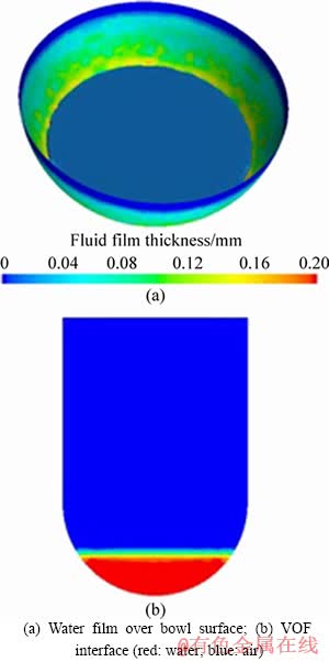
Figure 9 Water film over bowl surface and VOF interface:
Figure 10 shows the fluid-film thickness contours for EMU1 at different speeds, where the arrow represents the direction of the fluid-film flow. It also shows that the raindrops collide with the surface of the train to form a fluid film. The thickness of the fluid film at the train nose is the smallest and the minimum is approximately 0.05 mm. The maximum fluid-film thickness of up to 3.2 mm appears at the joint part between the bottom of the windshield and the train head.
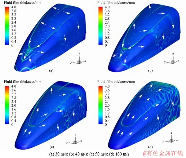
Figure 10 Fluid-film thickness contours for EMU1 with train velocity of:
When the train speed is 30 or 40 m/s, the fluid film at the upper part of windshield flows to both sides of the train head and flows down the side walls via its own force of gravity. The fluid film at the bottom part of the windshield flows down the windshield, accumulates at the joint part between the bottom of the windshield and the train head, and then flows down the train nose.
After the train speed exceeds 50 m/s, the fluid film over the entire windshield and train nose flows to the rear of the train head, and as the train speed increases, the flow direction of the fluid film tends to be parallel to the speed direction of the train. The fluid film at the side walls of the train head flows downward via gravity. We also find that rainwater accumulation occurs on the joint part between the windshield and the train head.
The change in the flow direction of the water film on the train surface that occurs when the train speed exceeds 50 m/s can be explained as follows. First, the surface pressure of the train and its components increase along the direction away from the nose tip as the speed increases, which is clearly shown in Figure 11. When the train speed increases from 30 to 100 m/s, the maximum surface pressure is increased from 748 to 5958 Pa. Second, according to previous studies, the shear force on the train surface increases when the train speed is increasing [21-23]. Both of these forces have the effect of pushing the water film away from the nose tip.
Figure 12 shows the fluid-film thickness contours of EMU2 at different speeds. Similar to EMU1, the fluid-film thickness at the train nose is the smallest. And as the train speed increases, the area with the smallest fluid-film thickness is gradually expanded. Rainwater does not accumulate over the windshield of EMU2 because of the convex shape, and the fluid-film thickness distribution is more uniform at the windshield.
When the train speed is 30 m/s, the fluid film at the upper part of windshield flows to both sides of the head reaches the side walls of the head and then flows down the side walls. The fluid film at the lower part of the windshield and the train nose moves downward along the walls.
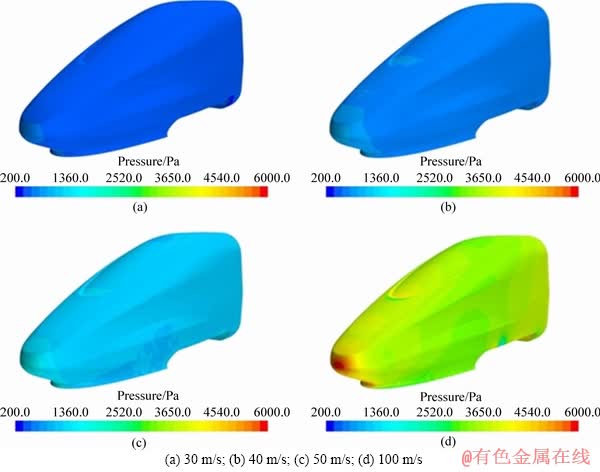
Figure 11 Pressure contours for EMU1 with train velocity:
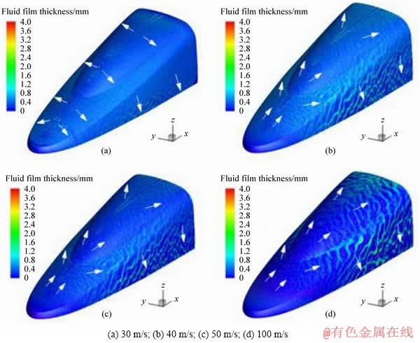
Figure 12 Fluid-film thickness contours for EMU2 with train velocity:
After the train speed exceeds 40 m/s, the fluid film over the entire windshield and train nose flows to the rear of the train head, and as the train speed increases further, the flow direction of the fluid film tends to be parallel with the speed direction of train. Similarly, the fluid film at the side walls of the train head flows downward via the force of gravity.
We can conclude from Figures 10 and 12 that a critical velocity occurs for the two types of windshields. When the train velocity is less than this critical velocity, the fluid film at the lower part of the windshield and train nose flows downward, and beyond the critical velocity, the fluid film over the entire windshield and train nose flows upward.
To investigate the influence of an uneven water film flowing over the windshield on the driver��s view, we selected the local area of the windshield (shown in the blue region of Figure 3) and statistically averaged the fluid-film thickness in this area. The results are given in Figure 13. For the concave windshield (EMU1), the average fluid-film thickness of approximately 0.33 mm varies little when the train speed is less than 50 m/s; however, when the train speed reaches 100 m/s, the average fluid-film thickness decreases to approximately 0.20 mm. For the convex windshield, the average fluid-film thickness of approximately 0.24 mm varies little over the entire range of speeds studied. Moreover, when the train speed is less than 50 m/s, the fluid-film thickness of the concave windshield is larger than that of the convex windshield. When the train speed reaches 100 m/s, the thicknesses of the two types of windshields are similar.
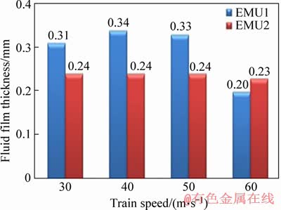
Figure 13 Fluid-film thickness versus train speed for EMU1 and EMU2
Figure 14 shows the change in surface pressure under both rain and no-rain conditions for computational model EMU2 at the speed of 40 m/s. The surface pressure with rainfall increases compared with that of the no-rainfall case, which is consistent with our intuitive expectation. The increased surface pressure is caused by the momentum transfer caused by raindrop impacts. Figure 15 shows a comparison of the pressure coefficient along the central line of the train surface. The range of the central line is from the tip of the nose to 2 m behind. The pressure coefficient at the nose is equal to 1 for both conditions as shown in Figure 15. The pressure coefficient drops suddenly at the corner of the nose tip where the curvature of the surface changes abruptly, thus creating a negative pressure region. For most of the surface regions, the pressure with rainfall is larger than that without rain, which is consistent with the conclusions of Figure 14.
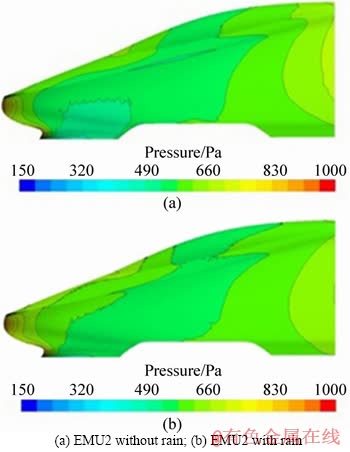
Figure 14 Pressure contours for EMU2 at 40 m/s:
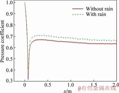
Figure 15 Comparison of pressure coefficient
In this study, the windshield and head train is taken into account as a whole section to study the accumulation of the rainfall around the two different windshields.
5 Conclusions
According to the standard set for the driver��s cab, the shape of the windshield should not affect the vision of the drivers, and the parameters of the windshield should match the shape of the head train [24]. Therefore, the shape of the windshield is determined by the shape of the head train. Thus, to investigate the accumulation of the rainfall on two different windshields means adopting two different head shapes.
The Lagrangian particle/fluid film/VOF coupled multiphase flow model proposed in this paper can well predict the impact of raindrops on train windshields and the flow behavior of water film along the surface. This model has high computational efficiency and can be applied to engineering problems involving multiphase flows of raindrops.
A critical velocity is observed for the two types of windshields. When the train velocity is less than this critical velocity, the fluid film at the upper part of the windshield flows to both sides of the head and the fluid film at the lower part of the windshield and train nose flows downward. However, when the train velocity is beyond the critical velocity, the fluid film at the entire windshield and train nose flows upward, and with further increases in train speed, the flow direction of the fluid film tends to be parallel with the speed direction of the train. The critical velocity is approximately 40 m/s for a concave windshield and approximately 30 m/s for a convex windshield.
Rainwater accumulation occurs at the joint part between the bottom of the windshield and the train head for the concave windshield, whereas rainwater accumulation occurs with the convex windshield. The average fluid-film thickness for the concave windshield is larger than that of the convex windshield when the train speed is less than 50 m/s; however, a minor difference is observed between these two values when train speed reaches 100 m/s.
The pressure at the surface of the windshield increases under rainfall compared with that under no rainfall because of the transfer of momentum caused by raindrop impacts.
References
[1] LUERS J K, HAINES P A. Heavy rain influence on airplane accidents [J]. Journal of Aircraft, 1983, 20(2): 187-191. DOI: 10.2514/3.44850.
[2] RHODE R V. Some effects of rainfall on flight of airplanes and on instrument indications [R]. NACA TN 803, 1941.
[3] LUERS J K. Heavy rain effects on aircraft [R]. AIAA, 1983.
[4] HANSMAN R J, CRAIG A P. Low Reynolds number tests of NACA 64-210, NACA 0012, and Wortmann FX67-K170 airfoils in rain [J]. Journal of Aircraft, 1987, 24(8): 559�C566. DOI: 10.2514/6.1987-259.
[5] CHANG Ying, ZHAO Lin, GE Yao-jun. Theoretical and testing investigation of wind/rain coupling loads on some typical bluff bodies [J]. Advances in Structural Engineering, 2019, 22(1): 156-171. DOI: 10.1177/1369433218781953.
[6] DONG Guo-chao, ZHANG Jian-ren, XUE Fan-rong, CAI Chun-sheng, HAN Yan. Numerical simulation of wind-rain coupling effect on typical bridge section based on Lagrangian system [J]. Journal of Hunan University (Natural Sciences), 2017, 44(9): 26-32. DOI: 10.16339/ j.cnki.hdxbzkb.2017.09.004. (in Chinese)
[7] OSHER S, SETHIAN J A. Fronts propagating with curvature-dependent speed: algorithms based on Hamilton�C Jacobi formulations [J]. Journal of Computational Physics, 1988, 79(1): 12-49. DOI: 10.1016/0021-9991(88) 90002-2.
[8] BRACKBILL J, KOTHE D B, ZEMACH C. A continuum method for modeling surface tension [J]. Journal of Computational Physics, 1992, 100(2): 335-354. DOI: 10.1016/0021-9991(92)90240-y.
[9] LI Gui-bo, LIAN Yong-sheng, GUO Yi-sen, JEMISON M, SUSSMAN M, HELMS T, ARIENTI M. Incompressible multiphase flow and encapsulation simulations using the moment-of-fluid method [J]. International Journal for Numerical Methods in Fluids, 2015, 79: 456-490. DOI: 10.1002/fld.4062.
[10] GIDASPOW D. Multiphase flow and fluidization [M]. Boston, America: Academic Press, 1994.
[11] CROWE C T, SMOOT L D. Multicomponent conservation equation [M]// Pulverized-Coal Combustion and Gasification. New York, America: Plenum Press, 1979.
[12] SHAO Xue-ming, WAN Jun, CHEN Da-wei, XIONG Hong-bing. Aerodynamic modeling and stability analysis of a high-speed train under strong rain and crosswind conditions [J]. Journal of Zhejiang University-Science A (Applied Physics & Engineering), 2011, 12(12): 964-970.
[13] JING Jun-e, GAO Guang-jun. Simulation of the action effect of wind-driven rain on high-speed train [J]. Journal of Railway Science and Engineering, 2013, 10(3): 99-102. DOI: 1672-7029 (2013) 03-0099-04. (in Chinese)
[14] WAN Jun. Aerodynamic and safety analysis for high speed trains under strong crosswind and heavy rain [D]. Hangzhou: Zhejiang University, 2012. (in Chinese)
[15] CUI Yang-yang. Development and application of multiphase flow models for high speed train based on OpenFOAM [D]. Hangzhou: Zhejiang University, 2012. (in Chinese)
[16] CHEN Wen-liang, WANG Zhan-li. The trial research on the behaviours of artificial rainfall by simulation [J]. Bulletin of Soil and Water Conservation, 1991, 11(2): 55-62. http://en.cnki.com.cn/Article_en/CJFDTOTAL-STTB199102010.htm. (in Chinese)
[17] BILANIN A J. Scaling laws for testing airfoils under heavy rainfall [J]. Journal of Aircraft, 1987, 24(1): 31-37. DOI: DOI: 10.1155/2013/590924.
[18] CD-adapco. Star-CCM+ documentation [M]. CD-adapco, 2015.
[19] YUE Yu-fei, ZENG Qiu-lan, LI Zhen-shan, LU Fu-an. Numerical simulation effects of rain-loaded wind on the aerodynamic characteristics and running stability of high-speed trains [J]. Journal of Desert Research, 2016, 36(4): 943-950. http://en.cnki.com.cn/Article_en/CJFDTO TAL-ZGSS201604011.htm. (in Chinese)
[20] XIONG Hong-bing, YU Wen-guang, CHEN Da-wei, SHAO Xue-ming. Numerical study on the aerodynamic performance and safe running of high-speed trains in sand storms [J]. Journal of Zhejiang University-Science A (Applied Physics & Engineering), 2011, 12(12): 971-978. DOI: 10.1631/jzus.A11GT005.
[21] NIU Ji-qiang, LIANG Xi-feng, ZHOU Dan. Experimental study on the effect of Reynolds number on aerodynamic performance of high-speed train with and without yaw angle [J]. Journal of Wind Engineering and Industrial Aerodynamics, 2016, 157: 36-46. DOI: 10.1016/j.jweia. 2016.08. 007.
[22] ZHANG Lei, YANG Ming-zhi, LIANG Xi-feng. Experimental study on the effect of wind angles on pressure distribution of train streamlined zone and train aerodynamic forces [J]. Journal of Wind Engineering and Industrial Aerodynamics, 2018, 174: 330-343. DOI: 10.1016/ j.jweia.2018.01.024.
[23] LI Xue-liang, WU Fan, TAO Yu, YANG Ming-zhi, NEWMAN Robert, VAINCHTEIN Dmitri. Numerical study of the air flow through an air-conditioning unit on high-speed trains [J]. Journal of Wind Engineering and Industrial Aerodynamics, 2019, 187: 26-35. DOI: 10 .1016/ j.jweia.2019.01.015.
[24] UIC 651. Layout of driver��s cabs in locomotives, railcars, multiple unit trains and driving trailers [S]. UIC651, 2002.
(Edited by ZHENG Yu-tong)
���ĵ���
�����г����粣����ˮ�������������Ե���ֵģ��
ժҪ�����Ľ�����ŷ��-������������/����Ĥ/VOF��϶�����ģ�͡��ڴ˻����ϣ�ͨ����ֵģ��ķ����о����������͵��粣������ˮ�ۼ����������ԡ�������������粣�������γ���һ�㲻���ȵ�ˮĤ�����浲�粣�����������ˮ�ۼ������浲�粣������û����ˮ�ۼ������г���������ʱ�����ε��粣����ƽ��ҺĤ��ȴ����ε��粣����Ȼ�������г�������ʻ������£�����֮��IJ����С�����⣬����ʹ���粣������Ĥ�����������ı���ٽ糵�١����г��ٶ�С���ٽ糵��ʱ�����粣���²�����Ĥ���г���ͷ���������������ٽ糵��ʱ���������粣�����г���ͷ�Ϸ�����Ĥ����������
�ؼ��ʣ������г������粣������ˮ�ۻ���������������
Foundation item: Projects(2016YFB1200602-11, 2016YFB1200602-12) supported by the National Key R&D Plan of China
Received date: 2018-11-30; Accepted date: 2019-08-24
Corresponding author: YANG Ming-zhi, PhD, Professor; Tel: +86-18373144664; E-mail: yqyymz@126.com; ORCID: 0000-0001- 7473-403X

