
Process optimization diagram based on FEM simulation for extrusion of AZ31 profile
LIU Gang(�� ��)1, ZHOU Jie(�� ��)2, J DUSZCZYK2
1. School of Materials Science and Engineering, Harbin Institute of Technology, Harbin 150001, China;
2. Department of Materials Science and Engineering, Delft University of Technology, Mekelweg 2, 2628 CD Delft, Netherlands
Received 12 June 2008; accepted 5 September 2008
Abstract: The ram speed and the billet temperature are the primary process variables that determine the quality of the extruded magnesium profile and the productivity of the extrusion operation. The optimization of the extrusion process concerns the interplay between these two variables in relation to the extrudate temperature and the peak extrusion pressure. The 3D computer simulations were performed to determine the effects of the ram speed and the billet temperature on the extrudate temperature and the peak extrusion pressure, thereby providing guidelines for the process optimization and minimizing the number of trial extrusion runs needed for the process optimization. A case study on the extrusion of an AZ31 X-shaped profile was conducted. The correlations between the process variables and the response from the deformed material, extrudate temperature and peak extrusion pressure, were established from the 3D FEM simulations and verified by the experiment. The research opens up a way to rational selection of the process variables for ensured quality and maximum productivity of the magnesium extrusion.
Key words: magnesium alloy; extrusion; process optimization diagram; FEM simulation
1 Introduction
Like the aluminum extrusion, the magnesium extrusion is a thermally activated deformation process [1-2]. As such, a thorough understanding of the relationship between the extrusion conditions and the thermomechanical response of a magnesium alloy to hot deformation holds the key to the process optimization. For a given die to manufacture a profile with certain cross-section geometry and dimensions, the billet temperature and the ram speed are the two primary process variables[3-5]. The response of the billet material to these two variables is reflected in the extrusion pressure required to push it through the die orifice (peak pressure) and the extrudate temperature at the die exit as a combined result of deformation and the friction between the deforming material and the extrusion tooling. The extrusion process optimization actually concerns the interplay between these two variables in relation to the peak pressure and the extrudate temperature[6]. A too high ram speed intended for a high throughput may result in scrap as a consequence of a too high extrudate temperature resulting in surface defects due to the local melting and the mechanical tearing at the die bearing[7]. In general, an adequate combination of a low billet temperature and a high ram speed leads to a good extrudate surface finish, however, this requires a high extrusion pressure[8-9]. Obviously, a too high pressure requirement will not allow the process to proceed through the breakthrough. It is highly desirable to minimize the number of trial runs and hopefully to start extrusion production with a set of process parameters optimized beforehand.
The FEM simulation has been applied to the magnesium extrusion to aid in gaining an understanding of its process thermomechanics. The extrusion behavior of a number of alloys, such as AZ31, AZ61 and ZK60, has been described through the two-dimensional (2D) FEM simulation[10] in the case of simple profile geometries. A kind of extrusion limit diagram was constructed based on the FEM simulations for the magnesium alloy AZ31. From the diagram, for each the extrusion speed, the region under the relevant curve defines the extrusion ratios that ensure the incipient melting temperature and the extrusion press capacity are not exceeded[7]. However, the diagram can only give a clue for a range of process variations, but not the optimal values. To limit the complications of the 2D FEM simulation and the computational time, the extrusion process was assumed to be adiabatic[11-12], which reflected the very nature of the thermally activated process to a less degree. Some researches were conducted by using the 3D FEM to show the metal flow inside the extrusion die and were helpful for analyzing the effects of the die design, billet temperature and ram speed on the profile quality[13-14].
The present research concerns the three-dimensional (3D) FEM simulation with the thermal effects incorporated to manufacture an extruded profile of industrial significance. It was aimed at establishing the correlations between the process variables, the peak pressure and the extrudate temperature through both the 3D FEM simulation and the experimental verification. And then a method to build up a process optimization diagram was presented.
2 Computer simulation and experimental details
2.1 Materials and geometry
AZ31 was used as an example billet material in this research. The H13 tool steel was used as the tooling material for the die, container and stem. Table 1 lists the physical properties of the billet and the extrusion tooling relevant to the 3D FEM simulation.
Fig.1 shows the X-shaped profile used as an example of the solid profiles. To take advantage of its symmetry, only the shaded portion was modelled. Two artificial symmetrical planes separating this portion from the rest of the profile were assumed to be immobile with no material moving across.
Table 2 lists the process parameters used both in the 3D FEM simulation and the extrusion experiments.
2.2 FEM simulation details
A DEFORM 3D software package (version 5.0) was

Fig.1 Cross section of X-shaped profile with shaded area selected for 3D FEM simulation (Unit: mm)
employed for computer simulation. Fig.2 shows the FEM models of the billet and the extrusion tooling that have been meshed with the tetrahedral elements. The AZ31 billet was considered the thermo-viscoplastic body, while the extrusion tooling as the thermo-rigid body. In other words, the elastic behaviour of the billet and the extrusion tooling was neglected, while the heat exchanges between the billet and the extrusion tooling were incorporated into the models.
The true flow stress�Cstrain data of the AZ31 alloy determined through hot compression tests[15] were used to describe the thermomechanical behaviour of the billet material during the hot extrusion. A shear friction model was applied to describe the interfacial friction during the magnesium extrusion, with the frictional force being fs=mk, where fs is the frictional stress, k is the shear yield stress and m is the friction factor. A friction factor of 1.0 was assigned at the interfaces between the billet material and the extrusion tooling to simulate the sticking friction condition.
2.3 Experimental verification
The results obtained from the 3D FEM simulations were verified by the extrusion experiments using a 2.5 MN extrusion press to extrude the AZ31 billet into the X-shaped profile as shown in Fig.1 under the conditions as specified in Table 2. The flat-faced die used had a uniform bearing length of 5 mm.
Table 1 Physical properties of AZ31 billet and H13 tool steel extrusion tooling

Table 2 Dimensions of billet and extrusion tooling and process parameters

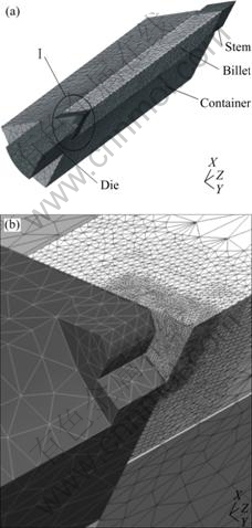
Fig.2 FEM models of billet and extrusion tooling to produce X-shaped profile as illustrated in Fig.1: (a) Whole models; (b) Close-up view of Area I in (a)
3 Results and discussion
3.1 Effect of billet temperature and ram speed on extrusion pressure
As mentioned early, the peak pressure is one of the parameters to watch when it comes to the extrusion process optimization, because it decides if the extrusion can be run successfully. Fig.3 shows the extrusion pressure/ ram displacement diagrams obtained from the 3D FEM simulation and the experiments. In this figure, ��s is the percentage of the length of the billet extruded, representing the ram displacement. It is clear that the peak pressure predicted from the 3D FEM simulation is quite close to that experimentally measured. The difference is, however, that in a real extrusion the breakthrough occurs later than a simulated extrusion, as a result of the neglected elastic deformation of the billet and the extrusion tooling during the simulation.
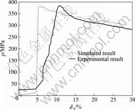
Fig.3 Simulated and experimental pressure and ram displacement diagrams at ram speed of 2 mm/s
Fig.4 shows the relationship between the peak pressure predicted pmax and the billet temperatures tb. It can be seen that tb has a strong influence on pmax. A 100 �� increase in tb from 350 to 450 �� leads to a 46% decrease in pmax, from 700 to 375 MPa. At any billet temperature, pmax increases with the rising ram speed vr. However, the magnitude of this increase is relatively insignificant; at a given tb, it increases by only about 15%, as vr increases from 2 to 8 mm/s. Therefore, to prevent the peak pressure from exceeding the maximum pressure of the press, adjusting the billet temperature is far more effective than adjusting the ram speed. This suggests that within a small margin below the maximum extrusion pressure of the press, for example, 700 MPa (see Fig.4), increasing tb slightly may produce a possibility to increase the extrusion speed considerably only if the extrudate temperature does not exceed the incipient melting point of the billet material which is around 532 �� for AZ31.

Fig.4 Variation of peak extrusion pressure with billet temperature at different ram speeds
3.2 Effect of billet temperature and ram speed on extrudate temperature
The predicted extrudate temperatures te at different billet temperatures and ram speeds are shown in Fig.5. It is clear that the extrudate temperature increases quickly at the transient stage of extrusion, i.e. over a short ram displacement range from ds=5% to ds=8% and afterwards it tends to be stable. The lower the initial billet temperature, the larger the rise of the extrudate temperature at the beginning of the process. Therefore, the thermal effects in the transient state of the process largely dictate the choice of billet temperature and ram speed.
The relationship between the rise of extrudate temperature ?te, defined as ?te=(te -tb)/tb��100% and tb at different vr is shown in Fig.6. It can be seen that vr has a strong effect on ?te; a moderately higher vr leads to a considerably larger ?te. In addition, the thermal effects are stronger when tb is lower. At 350 ��, for example, ?te ranges from 12% to 29% at the ram speeds of 2 to 8 mm/s. ?te decreases with increasing tb. When tb is as high as 475 ��, ?te becomes insignificant, suggesting that the process can be run nearly as an isothermal one.

Fig.5 Predicted extrudate temperature evolution during extrusion at different billet temperatures and ram speeds

Fig.6 Rise of extrudate temperature at different billet temperatures and ram speeds
3.3 Process optimization diagram
As mentioned earlier, in the extrusion operation, the peak pressure is limited by the press capacity, while the extrudate temperature is limited by the incipient melting temperature and the fracture strength of the billet material. An optimized process condition is such that the maximum pressure of the press is just not reached while the surface integrity of the extruded product is intact. One may start with assigning a desirable extrudate temperature from the metallurgical point of the view of the billet alloy and a desirable peak pressure, considering the pressure capacity of the press to be used, in order to come up with a pair of optimum billet temperature and ram speed.
The deviation of the predicted extrudate temperature te to the desired extrudate temperature t0 can be calculated by the equation ��=(t0-te)/t0. In the present study, if the extrudate temperature is desired to be 450 ��, i.e. t0=450 ��, the deviation �� at different billet temperatures is shown in Fig.7. It can be seen that when tb is low, vr must be high enough so that te can reach t0. Similarly, when vr is low, tb must be high enough for te reaching t0. If tb and vr are both high, te will exceed t0. To ensure te=t0, the billet temperature at the ram speed of 2 mm/s should be 437 ��, the billet temperature at the ram speed of 4 mm/s should be 413 ��, and the billet temperature at the ram speed of 8 mm/s should be 344 ��.
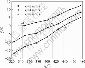
Fig.7 Deviation of predicted extrudate temperature to desired extrudate temperature
On the other hand, if the peak pressure is desired to be 700 MPa, for instance, the billet temperature should be 350 �� at the ram speed of 2 mm/s, 365 �� at 4 mm/s and 376 �� at 8 mm/s, i.e. the points J, K and L in Fig.4.
The conditions meeting both the desired extrudate temperature and peak pressure can be put into a process optimization diagram as shown in Fig.8. If the billet temperature and the ram speed fall in the left lower area of the t0 curve, the extrudate temperature will not be higher than t0. Likewise, if the billet temperature and the ram speed fall in the right lower area of the pmax curve, the peak pressure will not exceed the press capacity. Therefore, the conditions in the shared area are suitable for the extrusion of the AZ31 into the X-shaped profile. An optimized condition is the one close to the crossing point of the pmax and t0 curves, under which the desired extrudate temperature will be reached at the maximum ram speed, without excessive pressure requirement. In this particular case, the optimal ram speed is 6.3 mm/s and the optimal billet temperature is 372 ��.

Fig.8 Process optimization diagram for extrusion of X-shaped AZ31 profile
If the extrudate temperature is desired to be another value and the press capacity sets the limit at another peak pressure, a similar process optimization diagram can be constructed, following the step mentioned above. The diagram as shown in Fig. 8 can then be effectively used by the press operator to select an optimum combination of billet temperature and extrusion speed and to ascertain in advance that the extrudate temperature will not reach the incipient melting temperature and the peak pressure will not reach the press capacity, while the process can achieve the highest possible throughput with qualified surface finish.
4 Conclusions
1) The initial billet temperature has a stronger influence on the peak pressure than the ram speed. There may be opportunities to increase the ram speed within a margin of the extrusion pressures.
2) The rise of extrudate temperature occurs mostly at the beginning of an extrusion cycle. Thus, predicting the initial temperature rise is essential for the control of the process. The initial temperature rise is affected by the ram speed, especially when the billet temperature is low.
3) For an optimized extrusion condition, a desired peak pressure curve and a desired extrudate temperature curve can be drawn. The crossing point is the theoretical optimal condition subject to real extrusion trials.
Acknowledgements
Thanks are due to Mr. M A LEEFLANG for performing extrusion experiments to validate the results obtained from the 3D FEM simulation.
References
[1] KAIBYSHEV R O, SITDIKOV O, GALIEV A M. Mechanisms of plastic deformation in magnesium (��): Analysis of activation processes [J]. The Physics Metals Metallography, 1995, 80: 470-475.
[2] BRUNI C, DONATI L, MEHTEDI E, SIMONCINI M. Constitutive models for AZ31 magnesium alloys [J]. Key Engineering Materials, 2008, 367: 87-94.
[3] SHEPPARD T. Temperature and speed effects in hot extrusion of aluminium alloys [J]. Metals Tech, 1981, 8: 130-141.
[4] SABATER M, GARCIA-ROMEU M L, CIURANA J. Input parameters determination for predicting ram speed and billet temperature for the first billet [J]. Key Engineering Materials, 2008, 367: 161-168.
[5] MURAI T, MATSUOKA S, MIYAMOTO S, OKI Y. Effects of extrusion conditions on microstructure and mechanical properties of AZ31B magnesium alloy extrusions [J]. J Mater Process Tech, 2003, 141: 207-212.
[6] LI L, ZHOU J, DUSZCZYK J. Prediction of temperature evolution during the extrusion of 7075 aluminium alloy at various ram speeds by means of 3D FEM simulation [J]. J Mater Process Tech, 2004, 145: 360-370.
[7] LAPOVOK R Y, BARNETT M R, DAVIES C H J. Construction of extrusion limit diagram for AZ31 magnesium alloy by FE simulation [J]. J Mater Process Tech, 2004, 146: 408-414.
[8] HSIANG S H, LI Y W. Investigation of the influence of process parameters on hot extrusion of magnesium alloy tubes [J]. Journal of Materials Processing Technology, 2007, 192/193: 292-299.
[9] EMLEY E F. Principles of magnesium technology [M]. Oxford: Pergamon, 1966.
[10] OGAWA N, SHIOMI M, OSAKADA K. Forming of magnesium alloy at elevated temperatures for precision forming [J]. Int J Mach Tools & Manu, 2002, 42: 607-614.
[11] CHANDRASEKARAN M, JOHN Y M S. Effect of materials and temperature on the forward extrusion of magnesium alloys [J]. Mat Sci Eng A, 2004, 381: 308-319.
[12] YOON D J, LIM S J, JEONG H G, KIM E Z, CHO C D. Forming characteristics of AZ31B magnesium alloy in bidirectional extrusion process [J]. J Mater Process Tech, 2008, 201: 179-182.
[13] LI L, ZHANG H, ZHOU J, DUSZCZYK J, LI G Y, ZHONG Z H. Numerical and experimental study on the extrusion through a porthole die to produce a hollow magnesium profile with longitudinal weld seams [J]. Materials and Design, 2008, 29: 1190-1198.
[14] LIU G, ZHOU J, DUSZCZYK J. FE analysis of metal flow and weld seam formation in a porthole die during the extrusion of a magnesium alloy into a square tube and the effect of ram speed on weld strength [J]. Journal of Materials Processing Technology, 2008, 200: 185-198.
[15] LI L, ZHOU J, DUSZCZYK J. Determination of a constitutive relationship for AZ31B magnesium and validation through comparison between simulated and real extrusion [J]. J Mat Process Tech, 2006, 172: 372-80.
(Edited by LI Xiang-qun)
Foundation item: Project(2006BAE04B03) supported by the Chinese National S&T Program for the 11th Five-year Period
Corresponding author: LIU Gang; Tel: +86-451-86418631; E-mail: gliu@hit.edu.cn

