TiO2纳米管薄膜的裂纹起源、扩展与饱和
来源期刊:中国有色金属学报(英文版)2012年第3期
论文作者:邹俭鹏 WANG Ri-zhi
文章页码:627 - 633
关键词:TiO2纳米管;阳极氧化;界面剪切强度;裂纹;能量释放率
Key words:TiO2 nanotube; anodization; interfacial shear strength; cracking; energy release rate
摘 要:
通过阳极氧化法在Ti基体上垂直定向生长TiO2纳米管,其直径为60-80 nm,长度为4 μm。采用基体应变测试方法研究TiO2纳米管薄膜裂纹起源、扩展与饱和的情况。结果表明:退火可明显改善TiO2纳米管薄膜/Ti基体界面状况;随着拉伸应变的增加,裂纹扩展迅速加快,在很小的应变范围内达到饱和;TiO2纳米管薄膜室温样、250 °C退火样和400 °C退火样的界面剪切强度估算值分别为163.3、370.2和684.5 MPa,临界能量释放率分别为49.6、102.6和392.7 J/m2,断裂韧性分别为0.996、1.433和2.803 MPa?m1/2。TiO2纳米管薄膜的界面结合机制为化学键结合。
Abstract: Vertically orientated TiO2 nanotube array with diameters ranging from 60 up to 80 nm and length of 4 μm was grown on titanium by anodization. Crack initiation, propagation and saturation were studied using the substrate straining test. The results show that annealing obviously modifies the interfaces. With the increase of tensile strain, cracks in TiO2 nanotube films propagate rapidly and reach the saturation within a narrow strain gap. Interfacial shear strengths of TiO2 nanotube films without annealing, with 250 °C annealing and with 400 °C annealing can be estimated as 163.3, 370.2 and 684.5 MPa, respectively. The critical energy release rates of TiO2 nanotube films are calculated as 49.6, 102.6 and 392.7 J/m2, respectively. The fracture toughnesses of TiO2 nanotube films are estimated as 0.99
基金信息:the National Natural Science Foundation of China

![]()

Trans. Nonferrous Met. Soc. China 22(2012) 627-633
ZOU Jian-peng1, WANG Ri-zhi2
1. State Key Laboratory of Powder Metallurgy, Central South University, Changsha 410083, China;
2. Department of Materials Engineering, University of British Columbia, Vancouver BC, V6T 1Z4, Canada
Received 27 August 2011; accepted 16 November 2011
Abstract: Vertically orientated TiO2 nanotube array with diameters ranging from 60 up to 80 nm and length of 4 μm was grown on titanium by anodization. Crack initiation, propagation and saturation were studied using the substrate straining test. The results show that annealing obviously modifies the interfaces. With the increase of tensile strain, cracks in TiO2 nanotube films propagate rapidly and reach the saturation within a narrow strain gap. Interfacial shear strengths of TiO2 nanotube films without annealing, with 250 °C annealing and with 400 °C annealing can be estimated as 163.3, 370.2 and 684.5 MPa, respectively. The critical energy release rates of TiO2 nanotube films are calculated as 49.6, 102.6 and 392.7 J/m2, respectively. The fracture toughnesses of TiO2 nanotube films are estimated as 0.996, 1.433 and 2.803 MPa・m1/2, respectively. The interfacial bonding mechanism of TiO2 nanotube film is chemical bonding.
Key words: TiO2 nanotube; anodization; interfacial shear strength; cracking; energy release rate
1 Introduction
Recent studies using ever-improving methods have indicated that the fabrication of ordered TiO2 nanotube arrays can be achieved by anodization of titanium in an adequate electrolyte [1-3]. Due to its remarkable photoelectrochemical [4], gas sensing [5], and biological properties [6], TiO2 is used as photo catalysts for hydrogen generation [7], chemical sensors [8], dye sensitized solar cells [9], and bioactive coatings on titanium implants [10].
Till now, researches on TiO2 nanotube have been focused on the preparation, doping, synthesis mechanism and photo-sensitized materials application. But interfacial mechanical properties of the TiO2 nanotube have not been reported. The mechanical characterization of the TiO2 nanotube film is challenging because the small length scales are involved [11]. Substrate tensile straining test is a good method to investigate the interfacial properties through the crack initiation strain and the crack density at crack saturation strain. It was proposed by AGRAWAL and RAJ [12], and its theory was based on the shear lag model in the fiber reinforced composites. Shear lag model means that the stress of the film is transferred by the interface between the film and the substrate. The deformation response of sol-gel- derived zirconia thin films on 316L stainless steel substrates using a substrate straining test demonstrated that cracks were driven by deformation localized at slip bands on the substrate surface and the cracking pattern reflected the slip band pattern of the underlying substrate [13]. The interfacial shear strength of hydroxyapatite coatings on Ti6AlV substrates was evaluated by the shear lag strain method to range from 393 MPa for pure hydroxyapatite coating to 459 MPa for fluoridated hydroxyapatite coating [14].
In the present work, we reported the crack investigation results using substrate straining method during tensile test process. With AGRAWAL and RAJ’s model, interfacial shear strength, critical energy release rate and fracture toughness of TiO2 nanotube film were analyzed. Furthermore, the temperature annealing effects were particularly addressed.
2 Experimental
A pure annealed titanium foil (30 mm×30 mm, thickness 0.25 mm) bought from Goodfellows Co. was used in this study. Through mechanical processing, the foil was cut into 30 pieces of tensile test samples. The size of the tensile test samples is shown in Fig. 1. Grinding and polishing were carried out to get rid of stress concentration of the tensile test samples. After grinding one side and the edges of the samples with 1200 sand paper manually, the other side of the samples was polished with grinding-polishing machine automatically. 800 sand paper, 1200 sand paper, 6 μm diamond suspension, 1 μm diamond suspension, and silica colloid were used subsequently. The thickness of the polished Ti samples was controlled as (0.22±0.02) mm.
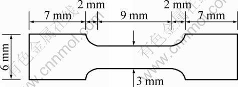
Fig. 1 Sketch of tensile test samples
A typical 2-electrode system was used for the anodization process. Pure titanium tensile test samples were used as the working electrode (anode), and a piece of platinum foil was used as the cathode. The polished side of the samples should face Pt electrode. Before anodizing, Ti foils were cleaned ultrasonically in acetone, absolute ethanol, and distilled water for 15 min sequentially, and air-dried. The anodization process was carried out in 98% ethylene glycol (C2H6O2) solution containing 0.27 mol/L ammonium fluoride (NH4F) at 30 V for 4 h, following the protocol of MACAK et al [15] with modified parameters. After the experiments, the samples were rinsed with distilled water 3 times for 30 s each. Thus, the TiO2 nanotube film was prepared on the titanium tensile test samples.
Tensile tests for the TiO2 nanotube film were carried out on a miniature materials testing machine (MINIMAT, Rheometic Scientific Co.). A typical stress―strain curve is given in Fig. 2. The stress―strain curve was basically the same as that of Ti substrate since the thickness of the film was much smaller than that of the substrate. Surface morphology of the tensile specimen was monitored during tensile test on a high speed CCD camera with high magnification zoom lens. The strain rate was controlled as 0.1 mm/min.

Fig. 2 Typical stress―strain curve of tensile test
250 °C annealing and 400 °C annealing were adopted to investigate the effects of annealing on the TiO2 nanotube film/substrate interface. The heating rate was 5 °C/min and the temperature-keeping time was 2 h.
Nanoindentation (Nano Indenter XP) was used to test the elastic modulus of TiO2 nanotube film. HITACHI S-3000N SEM was used to observe the microstructure of cracks of TiO2 nanotube film. NOVA nano SEM 230 (Field emission scanning electron microscopy, FESEM) was used to observe the morphology of TiO2 nanotube array.
3 Results and discussion
3.1 Elastic modulus measurement of TiO2 nanotube film
The elastic modulus was measured by nanoindentation (Nano Indenter XP). The indenter is a pyramidal Berkovich indenter which involves an optical imaging system and a lateral motion stage.
After the test sites are selected, the sample is automatically transported to below the indenter tip by the lateral motion stage, and tests are performed at the selected locations. The application of force involves an electromagnetic coil/magnet assembly, the range of load is 0.1 μN-10 N with a theoretical load resolution of 50 nN.
The projected area of contact (A) for Berkovich indenter is a function of the depth of penetration (hp) and the face angle (θ) [16].
![]() (1)
(1)
Then, the projected area of contact can be deduced as ![]() .
.
The load―displacement curves are recorded and the top unloading curves are used to calculate the reduced modulus Er.
![]() (2)
(2)
where S is the slope of the initial portion of the unloading curve, A is the projected area of contact and β is a dimensionless parameter, which is 1.034 for Berkovich indenter. The modulus of TiO2 nanotube film can be calculated as:
![]() (3)
(3)
where E and υ are the elastic modulus and Poisson ratio of the indented TiO2 nanotube film, respectively, and Ei and υi are those of diamond indenter, given as Ei=1141 GPa and υi=0.07. The value used for the Poisson ratio of the TiO2 nanotube film is 0.27. So, the elastic modulus of TiO2 nanotube film can be obtained as 20 GPa. CRAWFORD et al [11] reported that elastic modulus of TiO2 nanotubes was 36-43 GPa. The elastic modulus of TiO2 nanotube film obtained from nanoindentation is reasonable since it shows good agreement with the reports.
3.2 Microstructure of TiO2 nanotube array
The microstructures of TiO2 nanotube array are shown in Fig. 3. Nanofiber layers on the top of the nanotube film are shown in Fig. 3(a). The nanofibers are usually produced accompanying the production of TiO2 nanotube and the mechanism is not so clear now. The nanofibers can be removed by ultrasound for 5 min, as shown in Figs. 3(b) and (c). The diameter of the TiO2 nanotubes is estimated as 60-80 nm and the length is measured as 4 μm. During the tensile test, the nanofiber layers were kept to have an intact and unchanged interface between the TiO2 nanotube film and the substrate.
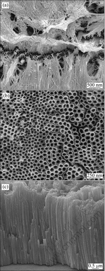
Fig. 3 Microstructures of TiO2 nanotube array: (a) Top view without ultrasound; (b) Top view with ultrasound for 5 min; (c) Side view with ultrasound for 5 min
3.3 Cracking investigation and temperature annealing effects
As shown in Fig. 4(a), crack initiation occurs at 1.6% strain point for the nanotube film without annealing. After this point, crack density increases rapidly. The TiO2 nanotube film reaches the crack saturation at the strain of 2.8% (Fig. 4(b)). The average steady-state crack spacing is equal to 16.37 μm. Typical crack density (number of cracks per unit length) for TiO2 nanotube film is illustrated in Fig. 5 as a function of strain.
Similar trends are observed for 250 °C annealing TiO2 nanotube film. As shown in Fig. 6, transverse cracks are first detected at a substrate strain level of 2.3% and crack saturation is achieved rapidly at strain level of 4.6%. The crack density versus strain for 250 °C annealing TiO2 nanotube film is shown in Fig. 7. As shown in Fig. 8, transverse cracks are first detected at a substrate strain level of 4.5% and crack saturation is achieved rapidly at strain level of 11.7% for 400 °C annealing TiO2 nanotube film. The crack density versus strain for 400 °C annealing TiO2 nanotube film is shown in Fig. 9. The average steady-state crack spacings of 250 °C and 400 °C annealing nanotube films are 10.4 μm and 11.01 μm, respectively.
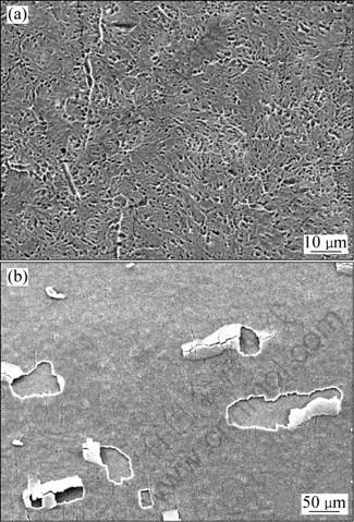
Fig. 4 SEM micrographs of crack patterns for TiO2 nanotube film without annealing: (a) 1.6% strain, crack initiation; (b) 2.8% strain, crack saturation
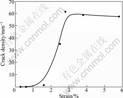
Fig. 5 Transverse crack density as function of strain for TiO2 nanotube film without annealing

Fig. 6 SEM micrographs of crack patterns for TiO2 nanotube film with 250 °C annealing: (a) 2.3% strain, crack initiation; (b) 4.6% strain, crack saturation
The shear lag strain method was used to assess the film/substrate interface shear strength [12]. Basically, this method relies on the development of transverse crack patterns in a brittle film when the relatively ductile supporting substrate is plastically deformed under anapplied uniaxial load. The ultimate interfacial shear strength is determined using a simplified equation for a film with thickness δ,
![]() (4)
(4)
where σc is the fracture stress of the ceramic film which is obtained by measuring the strain when the cracks begin to initiate; δ is the thickness of the film; and λmax is the maximum spacing of the cracks when the crack density becomes constant.

Fig. 7 Transverse crack density as function of strain for TiO2 nanotube film with 250 °C annealing
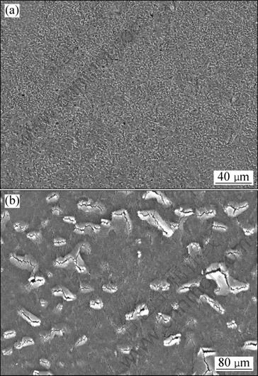
Fig. 8 SEM micrographs of crack patterns for TiO2 nanotube film with 400 °C annealing: (a) 4.5% strain; (b) 11.7% strain

Fig.9 Transverse crack density as function of strain for TiO2 nanotube film with 400 °C annealing
In Eq. (4), λmax is usually difficult to determine. AGRAWAL and RAJ modified it as [17,18]:
![]() (5)
(5)
where λ is the average crack spacing when the crack density becomes constant.
The fracture stress σc can be determined by:
![]() (6)
(6)
where E is the elastic modulus of the ceramic film, and εf is the applied strain with crack initiation. In our study, the average thickness of TiO2 nanotube film is 4 μm, the elastic modulus of TiO2 nanotube film is calculated as 20 GPa through nanoindentation method.
For TiO2 nanotube films without annealing, with 250 °C and 400 °C annealing, the crack initiation strains are 1.6%, 2.3% and 4.5%, respectively. So the fracture stresses of TiO2 films without annealing, with 250 °C and 400 °C annealing are calculated as 320, 460 and 900 MPa, respectively. Then, the interfacial shear strengths of TiO2 nanotube films without annealing, with 250 °C and 400 °C annealing, are estimated as 163.3, 370.2 and 684.5 MPa, respectively.
Another model proposed by MCGUIGAN et al [19] to evaluate the interfacial shear strength is τ=2ρhσc, where ρ is the average crack saturation density of the film. The average crack saturation densities of TiO2 nanotube films without annealing, with 250 °C and 400 °C annealing are 61.1, 96.1 and 90.8 mm-1, respectively. So, the interfacial shear strengths of TiO2 nanotube films without annealing, with 250 °C and 400 °C annealing are estimated as 156.4, 353.7 and 653.8 MPa, respectively. Excellent agreement of the interfacial shear strength for these two models can be obtained, which suggests that the interfacial shear strength results of the TiO2 nanotube film are reliable.
Crack initiation strains of 250 °C annealing samples (2.3%) and 400 °C annealing samples (4.5%) are higher than that of room temperature samples (1.6%). Once the crack saturation happens at the strain of 1.6%, some debonding appears in the TiO2 nanotube film without annealing. But debonding is not seen in TiO2 nanotube films with 250 °C and 400 °C annealing at the saturation strain point. The weaker the interface of the film/ substrate, the easier the formation of the debonding. Since debonding is not seen in the samples with 250 °C annealing and 400 °C annealing and debonding propagates rapidly in the samples without annealing, and the interfacial shear stresses of 250 °C and 400 °C annealing samples are much higher than that of room temperature samples, annealing obviously modifies the interfacial properties of the TiO2 nanotube film.
The fracture toughness in terms of critical energy release rate of the film can be calculated from [20]:
![]() (7)
(7)
 (8)
(8)
where h is the thickness of the film, σ is the fracture stress, and g(α,β) is a nondimensionalized integral of the crack opening displacement. In the case of no elastic mismatch, α=0, β=0, g(0,0)=1.12152. This result can be obtained by noting that ΔU, the change in elastic energy per unit depth in the film/substrate system, due to the introduction of the crack, must be given by [20]:
![]() (9)
(9)
g(α,β) can be also described as a dimensionless coefficient that depends on the Dundurs parameters α and β. For plain strain problems, α and β are [12]
![]() (10)
(10)
where![]() ;
;
![]() (11)
(11)
Let μi, Ei and υi(i=1,2) be the shear modulus, elastic modulus and Poisson ratio of the respective materials, and let κi=3-4υi for plane strain.
Equation (7) can be given as:
![]() (12)
(12)
In Eqs. (9-11), subscript “1” represents film and “2” represents metal substrate, and υ represents Poisson ratio. So, α=0.312,β=0.065 and g(α,β)=1.631 can be obtained. Subsequently, the critical energy release rates of TiO2 nanotube films without annealing, with 250 °C annealing and with 400 °C annealing are calculated as 49.6, 102.6 and 392.7 J/m2, respectively.
Table 1 Interfacial shear strength and related film parameters for TiO2 nanotube film

The relationship between the critical energy release rate Gc and fracture toughness KIC is given as follows [21]:
![]() (13)
(13)
Accordingly, the fracture toughnesses of TiO2 nanotube films without annealing, with 250 °C annealing and with 400 °C annealing are calculated as 0.996, 1.433 and 2.803 MPa・m1/2, respectively.
The calculated data of fracture stress, interfacial shear strength, critical energy release rate and fracture toughness of the nanotube films are given in Table 1.
When a ductile metal Ti substrate with a TiO2 nanotube film is subjected to uniaxial tension, the TiO2 nanotube film undergoes elastic deformation while the Ti substrate undergoes elastic-plastic deformation. The tensile stress in the substrate will eventually be transferred to the TiO2 nanotube film. Finally, the accumulated tensile stress in the film will reach the fracture strength of the film. Cracks appear on the TiO2 film in a direction perpendicular to the tensile test axis.
The TiO2 nanotube film is assumed to be linearly isotropic elastic and the substrate is modeled as an isotropic elastic-plastic solid. According to the von Mises rule [22], the shear strength is only ![]() of the tensile strength of the substrate. The tensile strength of titanium is 500 MPa approximately and the shear strength can be calculated as 288.7 MPa. It is reasonable since the estimated interfacial shear strength of TiO2 nanotube film without annealing (163.3 MPa) is much smaller than the calculated shear strength of pure titanium. Thus, the shear lag model analysis is valuable in understanding the fracture behavior of the TiO2 nanotube film both qualitatively and quantitatively.
of the tensile strength of the substrate. The tensile strength of titanium is 500 MPa approximately and the shear strength can be calculated as 288.7 MPa. It is reasonable since the estimated interfacial shear strength of TiO2 nanotube film without annealing (163.3 MPa) is much smaller than the calculated shear strength of pure titanium. Thus, the shear lag model analysis is valuable in understanding the fracture behavior of the TiO2 nanotube film both qualitatively and quantitatively.
At the same time, the film is well adherent to the substrate since the interfacial shear strength is relatively high. The bonding mechanisms in the film/substrate system include metallurgical bonding interface, diffusion bonding interface, prolongation growth mechanism, chemical bonding interface, molecular bonding interface and mechanical bonding interface. For TiO2 nanotube film prepared by anodization method, the nanotube film is obtained through chemical reaction between the Ti substrate and the electrolyte. So, chemical bonding comes into being at the interface between Ti substrate and TiO2 nanotube film and serves as bonding mechanism. Because the chemical bond in TiO2 nanotube film is covalent bond and the bonding strength of covalent bond is very high, the TiO2 nanotube film behaves strong bonding with the titanium substrate.
4 Conclusions
1) TiO2 nanotube film with the thickness of 4 μm and diameter of 60-80 nm was prepared on Ti substrate through anodization method. There was a strong bonding at the interface and the bonding mechanism was chemical bonding.
2) With AGRAWAL and RAJ’s model, the interfacial shear strengths of TiO2 nanotube films without annealing, with 250 °C annealing and with 400 °C annealing were estimated as 163.3, 370.2 and 684.5 MPa, respectively. And the critical energy release rates of TiO2 nanotube films were calculated as 49.6, 102.6 and 392.7 J/m2, respectively.
3) The relatively high interfacial shear strength and fracture toughness of TiO2 nanotube film with 250 °C annealing and with 400 °C annealing indicated the modifying effect of annealing.
Acknowledgement
The authors express their sincere thanks to Dr. Vincent EBACHER and Mr. Menghan MA for the technical support and valuable discussion during the course of this work.
References
[1] GONG D W, GRIMES C A, VARQHESE O K, HU W C, SINGH R S, CHEN Z, DICKEY E C. Titanium oxide nanotube arrays prepared by anodic oxidation [J]. Journal of Materials Research, 2001, 16(12): 3331-3334.
[2] LEE B G, CHOI J W, LEE S E, JEONG Y S, OH H J, CHI C S. Formation behavior of anodic TiO2 nanotubes in fluoride containing electrolytes [J]. Transactions of Nonferrous Metals Society of China, 2009, 19(4): 842-845.
[3] GUO Y G, HU J S, LIANG H P, WAN L J, BAI C L. TiO2-based composite nanotube arrays prepared via layer-by-layer assembly [J]. Advanced Functional Materials, 2005, 15(2): 196-202.
[4] SHANKAR K, BASHAM J I, ALLAM N K, VARGHESE O K, MOR G K, FENG X J, PAULOSE M, SEABOLD J A, CHOI K S, GRIMES C A. Recent advances in the use of TiO2 nanotube and nanowire arrays for oxidative photoelectrochemistry [J]. Journal of Physical Chemistry C, 2009, 113(16): 6327-6359.
[5] WANG Y, DU G, LIU H, LIU D, QIN S, WANG N. Nanostructured sheets of Ti-O nanobelts for gas sensing and antibacterial applications [J]. Advanced Functional Materials, 2008, 18(7): 1131-1137.
[6] OH S, DARAIO C, CHEN L H, PISANIC T R, FINONES R R, JIN S. Significantly accelerated osteoblast cell growth on aligned TiO2 nanotubes [J]. Journal of Biomedical Materials Research (Part A), 2006, 78(1): 97-103.
[7] LIU Y B, ZHOU B X, BAI J, LI J H, ZHANG J L, ZHENG Q, ZHU X Y, CAI W M. Efficient photochemical water splitting and organic pollutant degradation by highly ordered TiO2 nanopore arrays [J]. Applied Catalysis B: Environmental, 2009, 89(1-2): 142-148.
[8] GRIMES C A. Synthesis and application of highly ordered arrays of TiO2 nanotubes [J]. Journal of Materials Chemistry, 2007, 17: 1451-1457.
[9] MOR G K, VARQHESE O K, PAULOSE M, SHANKAR K, GRIMES C A. A review on highly ordered vertically oriented TiO2 nanotube arrays: fabrication, materials properties and solar energy applications [J]. Solar Energy Materials and Solar Cells, 2006, 90(14): 2011-2075.
[10] BAUER S, PARK J, Von Der MARK K, SCHMUKI P. Improved attachment of mesenchymal stem cells on super-hydrophobic TiO2 nanotubes [J]. Acta Biomaterialia, 2008, 4(5): 1576-1582.
[11] CRAWFORD G A, CHAWLA N, DAS K, BOSE S, BANDYOPADHYAY A. Microstructure and deformation behavior of biocompatible TiO2 nanotubes on titanium substrate [J]. Acta Biomaterialia, 2007, 3(3): 359-367.
[12] AGRAWAL D C, RAJ R. Measurement of the ultimate shear strength of a metal-ceramic interface [J]. Acta Metallurgica, 1989, 37(4): 1265-1270.
[13] KIRK P B, PILLIAR R M. The deformation response of sol-gel-derived zirconia thin films on 316L stainless steel substrates using a substrate test [J]. Journal of Materials Science, 1999, 34(16): 3967-3975.
[14] ZHANG S, WANG Y S, ZENG X T, CHENG K, QIAN M, SUN D E, WENG W J, CHIA W Y. Evaluation of interface shear strength and residual stress of sol-gel derived fluoridated hydroxyapatite coatings on Ti6Al4V substrates [J]. Engineering Fracture Mechanics, 2007, 74: 1884-1893
[15] MACAK J M, ALBU S P, SCHMUKI P. Towards ideal hexagonal self-ordering of TiO2 nanotubes [J]. Physica Status Solidi-Rapid Research Letters, 2007, 1(5): 181-183.
[16] HERRMANN M, SCHWARZER N, RICHTER F, FRUHAUF S, SCHULZ S E. Determination of Young’s modulus and yield stress of porous low-k materials by nanoindentation [J]. Surface & Coatings Technology, 2006, 201(7): 4305-4310.
[17] AGRAWAL D C, RAJ R. Ultimate shear strengths of copper-silica and nickel-silica interfaces [J]. Materials Science and Engineering A, 1990, 126(1-2): 125-131.
[18] GAN L, WANG J, PILLIAR R M. Evaluating interface strength of calcium phosphate sol-gel-derived thin films to Ti6Al4V substrate [J]. Biomaterials, 2005, 26(2): 189-196.
[19] MCGUIGAN A P, BRIGGS G A D, BURLAKOV V M, YANAKA M, TSUKAHARA Y. An elastic-plastic shear lag model for fracture of layered coatings [J]. Thin Solid Films, 2003, 424(2): 219-223.
[20] BEUTH J L Jr. Cracking of thin bonded films in residual tension [J]. International Journal of Solids Structures, 1992, 29(13): 1657-1675.
[21] YANG B Q, ZHANG K, CHEN G N, LUO G X, XIAO J H. Measurement of fracture toughness and interfacial shear strength of hard and brittle Cr coating on ductile steel substrate [J]. Surface Engineering, 2008, 24(5): 332-336.
[22] XIE C J, TONG W. Cracking and decohesion of a thin Al2O3 film on a ductile Al-5%Mg substrate [J]. Acta Materialia, 2005, 53: 477-485.
邹俭鹏1,WANG Ri-zhi2
1. 中南大学 粉末冶金国家重点实验室,长沙 410083;
2. Department of Materials Engineering, University of British Columbia, Vancouver BC, V6T 1Z4, Canada
摘 要:通过阳极氧化法在Ti基体上垂直定向生长TiO2纳米管,其直径为60-80 nm,长度为4 μm。采用基体应变测试方法研究TiO2纳米管薄膜裂纹起源、扩展与饱和的情况。结果表明:退火可明显改善TiO2纳米管薄膜/Ti基体界面状况;随着拉伸应变的增加,裂纹扩展迅速加快,在很小的应变范围内达到饱和;TiO2纳米管薄膜室温样、250 °C退火样和400 °C退火样的界面剪切强度估算值分别为163.3、370.2和684.5 MPa,临界能量释放率分别为49.6、102.6和392.7 J/m2,断裂韧性分别为0.996、1.433和2.803 MPa・m1/2。TiO2纳米管薄膜的界面结合机制为化学键结合。
关键词:TiO2纳米管;阳极氧化;界面剪切强度;裂纹;能量释放率
(Edited by YUAN Sai-qian)
Foundation item: Project (50604017) supported by the National Natural Science Foundation of China; Project (20110946Z) supported by the State Key Laboratory of Powder Metallurgy, China
Corresponding author: WANG Ri-zhi; Tel: +1-604-822-9752; E-mail: rizhi9752@hotmail.com
DOI: 10.1016/S1003-6326(11)61224-7

