Fracture evolution in coalbed methane reservoirs subjected to liquid nitrogen thermal shocking
��Դ�ڿ������ϴ�ѧѧ��(Ӣ�İ�)2020���6��
�������ߣ��Ϻ� ������ ������ Hani MITRI �¿��� �Ų�
����ҳ�룺1846 - 1860
Key words��liquid nitrogen; thermal shocking; coalbed methane; micro fracture; 3D via X-ray microcomputed tomography
Abstract: Thermal shocking effect occurs when the coalbed methane (CBM) reservoirs meet liquid nitrogen (LN2) of extremely low temperature. In this study, 3D via X-ray microcomputer tomography (��CT) and scanning electron microscope (SEM) are employed to visualize and quantify morphological evolution characteristics of fractures in coal after LN2 thermal shocking treatments. LN2 thermal shocking leads to a denser fracture network than its original state with coal porosity growth rate increasing up to 183.3%. The surface porosity of the ��CT scanned layers inside the coal specimen is influenced by LN2 thermal shocking which rises from 18.76% to 215.11%, illustrating the deformation heterogeneity of coal after LN2 thermal shocking. The cracking effect of LN2 thermal shocking on the surface of low porosity is generally more effective than that of high surface porosity, indicating the applicability of LN2 thermal shocking on low-permeability CBM reservoir stimulation. The characteristics of SEM scanned coal matrix in the coal powder and the coal block after the LN2 thermal shocking presented a large amount of deep and shallow progressive scratch layers, fracture variation diversity (i.e. extension, propagation, connectivity, irregularity) on the surface of the coal block and these were the main reasons leading to the decrease of the uniaxial compressive strength of the coal specimen.
Cite this article as: YAN Hong, TIAN Li-peng, FENG Rui-min, Hani MITRI, CHEN Jun-zhi, ZHANG Bo. Fracture evolution in coalbed methane reservoirs subjected to liquid nitrogen thermal shocking [J]. Journal of Central South University, 2020, 27(6): 1846-1860. DOI: https://doi.org/10.1007/s11771-020-4412-0.

J. Cent. South Univ. (2020) 27: 1846-1860
DOI:�� https://doi.org/10.1007/s11771-020-4412-0

YAN Hong(�Ϻ�)1, 2, 3, TIAN Li-peng(������)1, 2, FENG Rui-min(������)4,Hani MITRI3, CHEN Jun-zhi(�¿���)1, 2, ZHANG Bo(�Ų�)5
1. Key Laboratory of Deep Coal Resource Mining of Ministry of Education, Xuzhou 221116, China;
2. School of Mines, China University of Mining and Technology, Xuzhou 221116, China;
3. Department of Mining and Materials Engineering, McGill University, Montreal H3A 0E8, Canada;
4. Department of Chemical and Petroleum Engineering, University of Calgary, Calgary T2N 1N4, Canada;
5. Key Laboratory of Orogen and Crust Evolution, Peking University, Beijing 100871, China
 Central South University Press and Springer-Verlag GmbH Germany, part of Springer Nature 2020
Abstract: Thermal shocking effect occurs when the coalbed methane (CBM) reservoirs meet liquid nitrogen (LN2) of extremely low temperature. In this study, 3D via X-ray microcomputer tomography (��CT) and scanning electron microscope (SEM) are employed to visualize and quantify morphological evolution characteristics of fractures in coal after LN2 thermal shocking treatments. LN2 thermal shocking leads to a denser fracture network than its original state with coal porosity growth rate increasing up to 183.3%. The surface porosity of the ��CT scanned layers inside the coal specimen is influenced by LN2 thermal shocking which rises from 18.76% to 215.11%, illustrating the deformation heterogeneity of coal after LN2 thermal shocking. The cracking effect of LN2 thermal shocking on the surface of low porosity is generally more effective than that of high surface porosity, indicating the applicability of LN2 thermal shocking on low-permeability CBM reservoir stimulation. The characteristics of SEM scanned coal matrix in the coal powder and the coal block after the LN2 thermal shocking presented a large amount of deep and shallow progressive scratch layers, fracture variation diversity (i.e. extension, propagation, connectivity, irregularity) on the surface of the coal block and these were the main reasons leading to the decrease of the uniaxial compressive strength of the coal specimen.
Key words: liquid nitrogen; thermal shocking; coalbed methane; micro fracture; 3D via X-ray microcomputed tomography
Cite this article as: YAN Hong, TIAN Li-peng, FENG Rui-min, Hani MITRI, CHEN Jun-zhi, ZHANG Bo. Fracture evolution in coalbed methane reservoirs subjected to liquid nitrogen thermal shocking [J]. Journal of Central South University, 2020, 27(6): 1846-1860. DOI: https://doi.org/10.1007/s11771-020-4412-0.
1 Introduction
Coalbed methane (CBM) is an unconventional resource for natural gas [1]. By exploring and utilizing CBM, it can largely decrease the amount of the greenhouse gas emission and prevent methane-related accidents in coal mines. It can also achieve great economic benefits [2-4]. CBM reserves have exceeded 1.4��1014 m3 accounting for up to 20 % of the world��s natural gas resources [5]. However, the geological conditions of the CBM are complex, especially in deep rock strata [6]. The latest round of China��s oil and gas resources evaluation shows that the gas-in-place (GIP) of China��s CBM resources is about 29.8��1012 m3 at a depth shallower than 2000 m and approximately 12.5��1012 m3 is typically recoverable [7, 8]. Hydraulic fracturing technology is the main extraction method of CBM resources and has been applied up to 90 % of the gas wells and 70 % of the petroleum wells in recent years [9].
In the process of exploiting CBM with conventional hydraulic fracturing methods, one of the typical characteristics is that water is used mainly as the fracturing liquid material. However, the method will consume large amount of water. On the other hand, leakage of the fracturing liquid during the operation could seriously pollute the underground water and surrounding environment. Even worse, leakage could reach water shortage areas, which leads to the imbalance of the ecological environment [10-13]. Therefore, waterless fracturing technology with non-pollutant is beneficial to the surrounding environment. Nowadays, waterless fracturing technology includes oil-based and CO2 energized oil fracturing, explosives and propellant fracturing, gelled alcohol and LPG fracturing, gas fracturing, liquid/ supercritical CO2 fracturing and fracturing using the LN2 [9, 14]. The fracturing using the LN2 has remarkable advantages for the following reasons [15].
1) No pollution to the surrounding environment. LN2 is an inert gas, and there is no chemical reaction between the LN2 and the coal seam or rock strata. The thermal shocking effect between LN2 and the coal seam or rock strata will lead to coal fractures and simultaneously gasify itself. As a result, this type of fracturing liquid will not leave residue and pollute underground water.
2) Rich resource and low cost especially when applied at large scale. Nitrogen is a primary component of the air accounting for 78.08% of the atmosphere. Meanwhile, it is neither difficult nor expensive to switch from nitrogen to LN2.
3) Safe. LN2 is an inert gas, gas explosion will not occur during the transportation nor fracturing in the field. It will not initiate other materials to ignite or explode. Besides, the high compression ratio condition required to liquefy CO2 is not needed to maintain LN2.
4) Good general effect. Under the general pressure condition, the temperature of LN2 could be as low as -196 ��C. When LN2 comes in contact with the coal seam or rock strata, water in the pore of the coal seam or rock strata will quickly freeze in the endothermic process during the LN2 gasification, and it will produce about 9% volume expansion when the water changes to ice phase transition. Theoretically, this transition could produce frozen-heave pressure of about 207 MPa [16, 17], and it is much higher than the tensile strength of different metamorphic coal seams, which ranges from 0.28 to 2.35 [18, 19]. In this situation, there will exist lasting expansion and breakage of the coal seams after the LN2 thermal shocking.
Centering on the thermal shocking mechanism between LN2 and the coal/rock strata, many scholars have done related research. In the previous application trials, MCDANIEL et al [20] and GRUNDMANN et al [21] put the LN2 into 4 CBM trial wells in the United States and LN2 could effectively stimulate the CBM reservoirs to produce new fractures. In terms of experiments related to destructive methods, such as uniaxial compressive strength (UCS) test, tensile test and triaxial test, the results showed that both the UCS and tensile strength of coal specimens decreased after the LN2 thermal shocking, indicating fractures generation in the specimens [22-24]. Meanwhile, the fractures mainly propagated and extended nearby the LN2 injection hole in the triaxial loading experiment [25, 26]. The non-destructive experimental methods such as nuclear magnetic resonance (NMR) and metallographic microscopy, were mainly used to analyze the pore characteristics of coal fractures affected by the LN2 thermal shocking. ZHAI et al [27] found that thermal shocking effect deteriorated the coal structure, largely improving pore density and increasing the coal seam permeability. Later, ZHANG et al [28] observed that the length and width of the fractures on the surface of the coal specimen increased.
The above research results have well explored LN2 thermal shocking effect. However, with the limitation of equipment and the related monitoring technology, it is difficult to discern the pore distribution and its evolution characteristics inside the coal specimen after thermal shocking. Besides, there is an apparent lack of comparison between the spatial distribution morphology and evolution characteristics of the fractures. In fact, it is an important factor for determining and optimizing the key parameters of the LN2 fracturing technology. Aimed at the microstructure evolution of coalbed methane reservoirs subjected to LN2 thermal shocking, this paper explores the coal pore distribution and evolution characteristics using 3D CT scanning investigation method by 3D via X-ray microcomputed tomography (��CT) investigation. For ��CT scanned layers and the specimen, the calculation equations of the coal porosity were obtained and the coal porosity characteristics before and after the LN2 thermal shocking were analyzed. To carry out a more comprehensive pore characteristics and find out the reasons for the decrease of the coal strength, novelty SEM experiments including the coal powder and the coal block were respectively done, and the significant micro structure change in the coal matrix of the coal powder and fractures on the surface of the block were found. The findings of this study help better understand the fundamental mechanism of LN2 thermal shocking effect.
2 Equipment and testing process
A cylindrical coal specimen with a diameter of 25 mm and a length of 50 mm was cored from a coal block obtained from the Fenxi mining area, Shanxi, China. This coal had 75.78% fixed carbon and 16.27% volatile matter (measured by Chinese standard GB/T 212-2008 and DL/T 1030-2006). Mineral composition was measured using X-ray powder diffraction (XRD) and the result is shown in Table 1. The physical and mechanical properties of the coal specimen are listed in Table 2. The experiment used high-resolution ��CT scanning equipment located in the Advanced Analysis & Computation Center (AACC) in China University of Mining and Technology (CUMT), which consists of the scanning system (ZEISS Xradia 510 Versa), X-ray microscopy (X-ray sources, X-ray filters, Rotated stage, Detectors, etc.) and computer, as shown in Figure 1.
During the ��CT scan, the X-ray accelerating voltage and current were set to 70 kV, and the average time to acquire one full 3D image amounted was about 5 h. Due to the multiple influences of the coal specimen dimension, the exposure time of the experiments, and other factors, the pixel size was about 25 ��m. Note all the ��CT images were filtered with a 3D non-local means filter to denoise the image, and the object research systems (ORS) Visual SI was used for 2D/3D visualization and analysis. The thermal shocking experiments were conducted as follows (Figure 2).
Table 1 Linear thermal expansion coefficients of minerals

Table 2 Physical and mechanical properties of coal specimen


Figure 1 View of 3D via X-ray tomography apparatus:
1) The coal specimen was heated to 60 ��C using a drying oven at a heating rate of 1 ��C/min and kept in the oven for up to 24 h to release the water trapped in the microstructure. The specimen was considered completely dried when the change in mass was less than 0.2%.
2) The specimen was cooled to room temperature in a temperature and humidity controlled environmental chamber before starting the experiment. Due to the slow cooling process up to 6 h, this cooling step has very weak thermal shock and little deterioration in rock physical properties [32].
3) The specimen was then ��CT imaged at room temperature. In total, the specimen was scanned from top to bottom with a distance between two adjacent scanned layers of about 25 ��m.
4) The specimen was immersed in the LN2 reservoir for quenching for approximately 1 h and then equilibrated to room temperature for 30 min and then steps 1)-3) were repeated for the cooling treated specimen.
3 Results and analysis
3.1 Pore spatial evolution characteristics of coal specimen before and after LN2 thermal shocking
As shown in Figure 3, there is a significant change in the ��CT scanned coal specimen pore structure after suffering from the LN2 thermal shocking. Before LN2 thermal shocking, the pores within the specimen were generally dispersed throughout. They were separated with weak connectivity. After LN2 thermal shocking, the pore connectivity was significantly increased and the spatial structure became much more complicated. The size of the pores also generally increased, with several wide pores existing after quenching. Furthermore, the length of the pores extended and new fractures propagated after the thermal shocking, and multiple stereo channels occurred. This indicates that the coal specimen experienced strong frost heaving due to the LN2 treatment. The porosity before the thermal shocking considered the baseline in this study to analyze the effect of LN2 quenching on the total rock porosity. LN2 thermal shock induced whole porosity growth rate ���� is defined as follows:
 (1)
(1)
where ��t is the coal specimen porosity after thermal shocking, and ��f is the coal specimen��s original porosity before thermal treatments.
According to the porosity comparison results before and after LN2 thermal shocking, the porosity increased from the original 0.54% to 1.53% after treatment, with an overall growth rate of 183.3%. This indicates that the thermal shocking effect is significant. As the coal specimen was thoroughly dried (drying up to 24 h at the 60 ��C) before immersing into the liquid nitrogen reservoir, LN2 fracturing could significantly improve the coal seam permeability without water consumption and it is a benefit to the exploration of CBM reservoirs.

Figure 2 Schematic of experimental apparatus and flowchart for thermal treatment

Figure 3 3-D visualization of micro-fracture of core:
3.2 Porosity change characteristics for each layer suffering from LN2
In order to analyze the pore morphology within the coal specimen and porosity change before and after LN2 thermal shocking, nine intermediate locations with a spacing of 162/163 layers were then extracted from the remaining 1300 scans taken by the 3D digital specimen scan to investigate the structure changes of the fractures before and after LN2 thermal shocking. The nine locations are identified in Table 3. For simplicity of comparison, the nine layers are indexed by A1-A9 and B1-B9 before and after the LN2 thermal shocking, respectively.
Two features can be readily observed from Figures 4 and 5. First, the pre-existing fractures in all cross-sections propagated to some extent after the thermal shocking, illustrating that the tensile stress induced by the thermal treatments deteriorates the coal strength. Second, new fractures formed, as clearly shown by comparing image A5 and B5 (Figures 6(a) and (b)). Both the extension of the existing fractures and the propagation of the new fractures can be attributed to the large discrepancy in the thermal expansion coefficients between different minerals. The mineral thermal expansion coefficient is a critical parameter tightly related to rock damage during thermal treatment. As listed in Table 1, the thermal expansion coefficient of the minerals differs significantly with each other, which leads to different thermal response after the thermal treatments.
Table 3 Locations of sections along 3D digital rock

3.3 Pore change characteristics of single scanned layer comparison before and after LN2 thermal shocking
3.3.1 CT Scanning porosity calculation
For the CT-scanned cylindrical coal specimen, as shown in Figure 7(a), the porosity of the specimen is classified as surface porosity with a single scanned layer cut by the circle face and bulk porosity of the whole specimen in our study.
As shown in Figure 7(b), the surface porosity of a CT scanned layer is defined as the ratio between the sum of the pore space area and the whole cross-sectional area, mathematically expressed as:

Figure 4 2D images after LN2 thermal shocking
 (2)
(2)
where ��i is the surface porosity of a CT scanned layer; Sif is sum of the pore space area, mm2; Sis is the cross-sectional area, mm2.
After the CT scanning, a supposing square containing fractures and pixels is formed, and the relationship between the square, the scanned cross-section of the coal specimen and fractures on the cross-section face is shown in Figure 8. The pixel of the CT scan equipment is much smaller than the dimension of the fractures, the proper grey threshold was used to recognize the pore, and the number of pixels was used to measure the area of the fractures [33, 34]. Supposing that the number of the micro pore is N, and the pixel value is x, then Eq. (2) could be presented as:

 (3)
(3)
where S is the square area for a cross-section face, mm2; Ni is the number of micro-pores in the ith cross-section layer; Mi is the number of the pixels in the ith cross-section layer; Pi is the number after the number of pixels in the square minus the number of pixels in the cross-section layer.
The bulk porosity of the whole specimen is the ratio of the pore volume to the coal specimen volume. According to the stacking calculation of each scanned layer, supposing that the scanned layer is n, and the number of the fractures in each CT scanned layer is respectively N1, N2, N3, ��, Nn, and the whole porosity can be expressed as:

Figure 5 2D images before LN2 thermal shocking

Figure 6 850th ��CT scan layer of coal specimen:

Figure 7 CT scanned coal specimen (a) and pore distribution (b) on a layer

Figure 8 Diagram of CT scanned surface pore of coal specimen:
 (4)
(4)
where Vf is the coal pore volume, mm3; Vs is the coal specimen volume, mm3; V is the cubic volume, mm3; V0 is the rest volume of cubic volume subtracting the coal specimen volume, mm3.
3.3.2 Relationship between original surface porosity and LN2 thermal shocking effect
The surface porosity of each cross-section before thermal shocking is considered a baseline in this study to analyze the effect of LN2 quenching on rock inner surface porosity. The LN2 thermal shock induced surface porosity growth rate ����s is defined as follows:
 (5)
(5)
where ��ts is the surface porosity after thermal shocking, and ��is is the initial surface porosity before thermal treatments.
A total of 25 scanned cross-section layers from top to bottom of the coal specimen are selected, as shown in Table 4, Figures 9 and 10. The initial porosity and surface porosity growth rates of each cross-section are plotted in Figure 11. The range of the initial porosity is 0.22%-1.56%, and the range of the surface porosity growth rate of the 25 layers after thermal shocking is calculated by Eq. (5). The surface porosity growth rate ranges from 18.76% to 215.11%, which indicates that both the coal specimen��s initial porosity and surface porosity are significantly different after LN2 thermal shocking. In order to clarify the changes in the porosity before and after the LN2 thermal shocking, nine- crosssectional layer group is selected to analyze in detail, as marked in Table 4. As shown in Figures 9 and 10, compared with the initial porosity before the LN2 thermal shocking, the surface porosity generally significantly changed after thermal shocking. For example, porosity is only 0.28% in layer 904 (Figure 9(f)). However, the porosity increases to 0.88% after treatment (Figure 10(f)), more than three times of the former. The positive surface growth rate values indicate that LN2 thermal treatments promote the extension of the pre-existing fractures and propagation of new fractures, although the positions of the fracture propagation and fractures extension directions are quite different.
Table 4 Selected scan layers along 3D digital rock


Figure 9 Initial porosity before LN2 thermal shocking:

Figure 10 Porosity after LN2 thermal shocking:
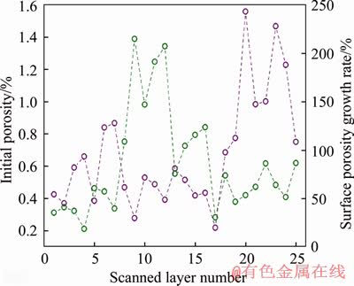
Figure 11 ��CT scan of porosity change under LN2 thermal shocking
Figure 12 shows the relationship between the initial surface porosity and the porosity growth rates. One unique feature is that the surface porosity growth rate of the cross-sections with small initial porosity is generally higher than those with large initial porosity. When the initial porosity is less than 0.6%, a majority of the surface porosity growth rates is greater than 100%; however, when the initial porosity is greater than 0.6%, all the surface porosity growth rates are less than 100%.
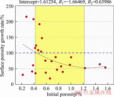
Figure 12 Surface porosity of different sections along axial specimen
The cross-section with large initial porosity can accommodate the thermal deformation and weaken the constrains between different mineral particles. This, in turn, reduces the thermal stress-induced damage, and restricts the development of new fractures or pre-existing fracture propagation. In contrast, for the cross- section with low porosity, the thermal stress between different mineral/particles is significantly high because there is no enough space to accommodate thermal deformation. When the thermal stress/frost-heave stress is greater than the critical tensile stress of the coal, new fractures form or pre-existing fractures propagate. This finding illustrates that LN2 fracturing has vast potential to significantly deteriorate reservoir rocks, and thus enhance their permeability, especially, for rocks with low initial permeability.
3.4 Relation between coal strength and LN2 thermal shocking
Coal is composed of coal matrix and fracture system, where the fracture system provides the primary pathways for fluid flow in coal [35, 36]. Therefore, the changes in surface morphology of the coal matrix after thermal shocking and its influence on the fracture system is also a concern in our study.
The above scanning testing results show that the number of the fractures in each cross-section layers increases, the original fractures extend, and a complex spatial reticular structure forms, which leads to a decrease of the coal specimen strength. CAI et al [22] and JIN et al [37] tested the UCS of the coal specimens before and after LN2 thermal shocking treatments and observed a decrease in the UCS from 15.84% to 33.74%. In fact, apart from the concluded porosity increment, it is unknown if the coal matrix would also change and promote a strength decrease suffering from the LN2. In order to thoroughly address this problem, an experiment is designed and tested, as shown in Figure 13. Two coal specimens are collected from the same large coal block used in Figure 2 to determine the change in strength induced by the LN2 thermal shocking. The dimensions are less than 1 cm��1 cm��1 cm. The specimens are respectively named 1# and 2#. Coal specimen 1# was dried in the drying oven for 32 h at 60 ��C. The experiment process of coal specimen 2# has three steps as follows. Firstly, dried as the coal specimen 1#; secondly, the dried coal specimen is immersed into the LN2 reservoir for 1 h, and then removed from the LN2 reservoir and equilibrated to room temperature for approximately 1 h; thirdly, coal specimen 2# is thoroughly dried again as the first step condition. After the two coal specimens are prepared, they are sequentially ground and sieved to obtain a coal powder with a dimension less than 300 mesh, and then scanned with a scanning electron microscope.
The scanning results of the coal power under SEM are shown in Figure 14, including two conditions before and after LN2 thermal shocking treatments. There are many significant deep and shallow progressive scratch layers. Firstly, this type of characteristic changes the surface uniformity of the micro-structure of the coal matrix, and the separate layer structure promotes a decrease in the UCS of the coal specimen. Secondly, the change in the coal matrix morphology, such as sections of layers with depressions or salient, is beneficial for forming large pores and promoting extension of the original fractures.
Based on the comprehensive experimental studies on the micro-structure evolution characteristics of coal and two types of scanned coal powder, the fractures changes of coal specimen with flat surface suffering from LN2 are investigated. The small coal specimen from the same large coal block used in Figure 2 is collected and processed with dimensions less than 1 cm��1 cm��1 cm, as shown in Figure 15, and one of the specimen faces is flat to explore the characteristics of the fracture before and after the LN2 thermal shocking with SEM. As shown in Figure 16, the SEM scanning results show that several new fractures propagate and parts of the preexisting fractures extend and connect. Some embedded attachments are scoured, which leads to several micro-holes or unorganized fractures on the surface, all of which could affect the coal specimen strength and significantly improve CBM reservoir recovery.
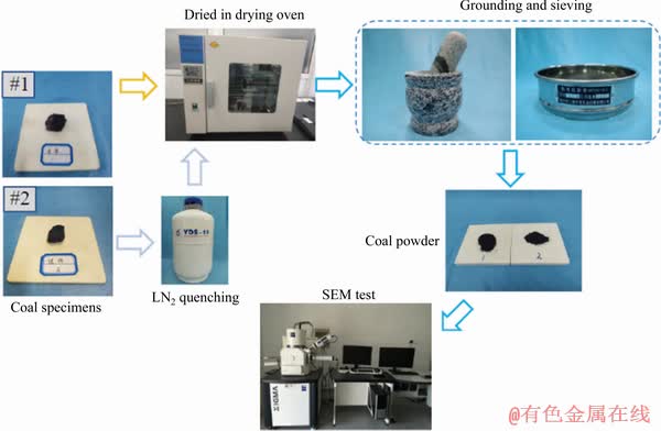
Figure 13 Flowchart of experimental process
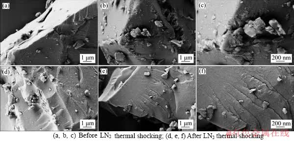
Figure 14 Scanning results of coal powder with SEM before and after LN2 thermal shocking:
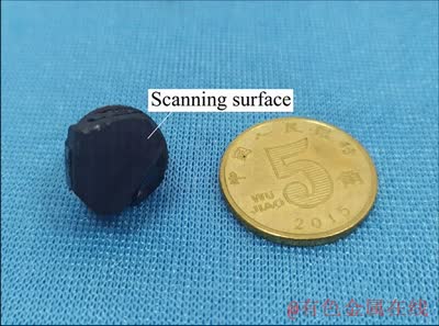
Figure 15 Experimental coal block
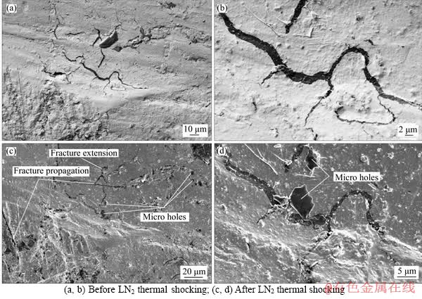
Figure 16 Scanning results of coal block with SEM before and after LN2 thermal shocking:
4 Conclusions
1) LN2 thermal shocking significantly affects the distribution characteristics of the coal pore, namely, coal pore connectivity is greatly strengthened; spatial distribution of the coal pore becomes much more complex; coal pore density generally increases; new fractures propagate and multiple stereo channels form.
2) The experimental coal porosity increases after the LN2 thermal shocking. The stereoscopic distribution diagrams of the pore before and after the LN2 thermal shocking are obtained using 3D X-ray microcomputed tomography, and the LN2 thermal shock inducing whole porosity growth rate is up to 183.3%.
3) The surface porosity growth rate after LN2 treatment is approximately inversely related to the original surface porosity of coal, which indicates that LN2 fracturing has the prospect for broad application in stimulating coalbed methane reservoirs of low porosity and permeability.
4) The mathematical equations for the CT scanning porosity of the cylindrical coal specimen are determined, and the degree of influence of LN2 thermal shocking greatly varies amongst layers.
5) The decrease in the UCS of the coal specimen after the LN2 thermal shocking is attributed to the intense microstructure changes in the coal matrix, coal porosity increasing and fracture variation diversity in the specimens.
Acknowledgements
We are grateful for HE Xiang-qian in Fenxi Mining Group Co., Ltd., XIE Wei-ning in the Advanced Analysis & Computation Center, XIA Wang-suo in the School of Physics in CUMT, for their valuable comments for the improvement of this paper.
References
[1] TIAN Fu-chao, LIANG Yun-tao, WANG De-ming, JIN Kan. Effects of caprock sealing capacities on coalbed methane preservation: Experimental investigation and case study [J]. Journal of Central South University, 2019, 26: 925-937. DOI: 10.1007/s11771-019-4061-3.
[2] FABRIZIO C, RUSSELL T, JONATHAN R L, KEVIN G T, CHRISTOPHER B, ANTHONY D M, RICHARD L, ROBERT M K. Biogenic methane in shale gas and coal bed methane: A review of current knowledge and gaps [J]. International Journal of Coal Geology, 2016, 165: 106-120. DOI: 10.1016/j.coal.2016.08.011.
[3] XIE Sheng-rong, ZHAO Yao-jiang, ZHANG Shou-bao, YANG Hong-zeng, XIAO Dian-cai, TIAN Chun-yang. Mechanism and experiment of substituting high drainage roadway with directional long drilling group to extract pressure-relief gas [J]. Journal of Central South University, 2012, 19: 2591-2597. DOI: 10.1007/s11771-012-1315-8.
[4] MANASI M M, BHATU K P. Sorption behavior of coal for implication in coal bed methane an overview [J]. International Journal of Mining Science and Technology, 2017, 27: 307-314. DOI: 10.1016/j.ijmst.2017.01.014.
[5] DANIEL J G, PAUL B, NIGEL B, ADAM D H. Assessing the impact of future greenhouse gas emissions from natural gas production [J]. Science of the Total Environment, 2019, 668: 1242-1258. DOI: 10.1016/j.scitotenv.2019.03.048.
[6] DING Zi-wei, JIA Jin-dui, FENG Rui-min. Effect of the vertical stress on CO2 flow behavior and permeability variation in coalbed methane reservoirs [J]. Energy Science Engineering, 2019, 7: 1937-1947. DOI: 10.1002/ese3.402.
[7] TAO Shu, PAN Zhe-jun, TANG Shu-ling, CHEN Shi-da. Current status and geological conditions for the applicability of CBM drilling technologies in China: A review [J]. International Journal of Coal Geology, 2019, 202: 95-108. DOI: 10.1016/j.coal.2018.11.020.
[8] TAO Shu, CHEN Shi-da, PAN Zhe-jun. Current status, challenges, and policy suggestions for coalbed methane industry development in China: A review [J]. Energy Science & Engineering, 2019, 7(4): 1059-1074. DOI: 10.1002/ ese3.358.
[9] WANG Lei, YAO Bo-wen, CHA Min-su, NAIF B A, TAYLOR W P, TIMOTHY J K, JENNIFER L M, YIN Xiao-long, WU Yu-shu. Waterless fracturing technologies for unconventional reservoirs opportunities for liquid nitrogen [J]. Journal of Natural Gas Science and Engineering, 2016, 35: 160-174. DOI: 10.1016/j.jngse.2016.08.052.
[10] SINAL M L, LANCASTER G. Liquid CO2 fracturing: Advantages and limitations [J]. Journal of Canadian Petroleum, 1987, 26(5): 26-30.
[11] JACKSON R E, GORODY A W, MAYER B, ROY J W, RYAN M C, van STEMPVOORT D R. Groundwater protection and unconventional gas extraction: the critical need for field-based hydrogeological research [J]. Groundwater, 2013, 51(4): 488-510. DOI: 10.1111/gwat. 12074.
[12] HILARY B, CHRISTOPHER C, DYLAN B, EDWARD M, CONNIE R, ANTHONY L. ��Fracking�� controversy and communication: using national survey data to understand public perceptions of hydraulic fracturing [J]. Energy Policy, 2014, 65: 57-67. DOI: 10.1016/j.enpol.2013.10.017.
[13] LI Zi-feng, XU Hong-fang, ZHANG Chao-yue. Liquid nitrogen gasification fracturing technology for shale gas development [J]. Journal of Petroleum Science and Engineering, 2016, 138: 253-256. DOI: 10.1016/j.petrol. 2015.10.033.
[14] HOU Xiang-qian, LU Yong-jun, FANG Bo, QIU Xiao-hui, CUI Wei-xiang. Waterless fracturing fluid with low carbon hydrocarbon as base fluid for unconventional reservoirs [J]. Petroleum Exploration and Development, 2013, 40(5): 646-650. DOI: 10.1016/S1876-3804(13)60085-3.
[15] YAN Hong, TIAN Li-peng, FENG Rui-min, MITRI H, CHEN Jun-zhi, HE Kang, ZHANG Yuan, YANG Shun-chao, XU Zhi-jun. Liquid nitrogen waterless fracking for the environmental protection of arid areas during unconventional resource extraction [J]. Science of the Total Environment, 2020, 721: 137719. DOI: 10.1016/j.scitotenv.2020.137719.
[16] SANDSTROM T, FRIDH K, EMBORG M, HASSANZADEH M. The influence of temperature on water absorption in concrete during freezing [J]. Nordic Concrete Research, 2012, 45(1): 45-58.
[17] QIN Lei, ZHAI Cheng, LIU Shi-min, XU Ji-zhao, TANG Zong-qing, YU Guo-qing. Failure mechanism of coal after cryogenic freezing with cyclic liquid nitrogen and its influences on coalbed methane exploitation [J]. Energy Fuels, 2016, 30(10): 8567-8578. DOI: 10.1021/acs.energyfuels. 6b01576.
[18] WU Ji-wen, FAN Cheng. Laboratory test on tensile strength of coal piece by sleeve fracturing technique [J]. Coal Geology & Exploration, 2003, 31(1): 19-21. (in Chinese)
[19] QI Qing-xin. Study experimental on direct uniaxial tensile properties of coal [J]. Coal Mining Technology, 2001(4): 15-18. (in Chinese)
[20] MCDANIEL B W, GRUNDMANN S R, KENDRICK W D, WILSON D R, JORDAN S W. Field applications of cryogenic nitrogen as a hydraulic-fracturing fluid [J]. Journal of Petroleum Technology, 1998, 50(3): 38-39.
[21] GRUNDMANN S, RODVELT G, DIALS G, ALLEN R. Cryogenic nitrogen as a hydraulic fracturing fluid in the Devonian shale [C]// SPE Eastern Regional Meeting. Pittsburgh, Pennsylvania: SPE. 1998: 1-6.
[22] CAI Cheng-zheng, LI Gen-sheng, HUANG Zhong-wei, TIAN Shou-ceng, SHEN Zhong-hou, FU Xuan. Experiment of coal damage due to super-cooling with liquid nitrogen [J]. Journal of Natural Gas Science and Engineering, 2015, 22: 42-48. DOI: 10.1016/j.jngse.2014.11.016.
[23] CAI Cheng-zheng, GAO Feng, LI Gen-sheng, HUANG Zhong-wei, HOU Peng. Evaluation of coal damage and cracking characteristics due to liquid nitrogen cooling on the basis of the energy evolution laws [J]. Journal of Natural Gas Science and Engineering, 2016, 29: 30-36. DOI: 10.1016/ j.jngse.2015.12.041.
[24] GAO Feng, CAI Cheng-zheng, YANG Yu-gui. Experimental research on rock fracture failure characteristics under liquid nitrogen cooling conditions [J]. Results in Physics, 2018, 9: 252-262. DOI: 10.1016/j.rinp.2018.02.061.
[25] QIN Lei, ZHAI Cheng, LIU Shi-min, XU Ji-zhao, YU Guo-qing, SUN Yong. Changes in the petrophysical properties of coal subjected to liquid nitrogen freeze-thaw�CA nuclear magnetic resonance investigation [J]. Fuel, 2017, 194: 102-114. DOI: 10.1016/j.fuel.2017.01.005.
[26] QIN Lei, ZHAI Cheng, LIU Shi-min. Infrared thermal image and heat transfer characteristics of coal injected with liquid nitrogen under triaxial loading for coalbed methane recovery [J]. International Journal of Heat and Mass Transfer, 2018, 118: 1231-1242. DOI: 10.1016/j.ijheatmasstransfer.2017. 11.051.
[27] ZHAI Cheng, QIN Lei, LIU Shi-min, XU Ji-zhao, TANG Zong-qing, WU Shi-liang. Pore structure in coal: Pore evolution after cryogenic freezing with cyclic liquid nitrogen injection and its implication on coalbed methane extraction [J]. Energy Fuels, 2016, 30: 6009-6020. DOI: 10.1021/acs. energyfuels.6b00920.
[28] ZHANG Dong, WANG Qiao, LI Da-yuan, FENG Zeng-chao. Experimental study on infiltration and freeze�Cthaw damage of water-bearing coal samples with cryogenic liquid nitrogen [J]. Journal of Natural Gas Science and Engineering, 2018, 60: 24-31. DOI: 10.1016/j.jngse.2018.09.027.
[29] MCKINSTRY H A. Thermal expansion of clay minerals [J]. American Mineralogist, 1965, 50(1, 2): 212-222.
[30] IGARASHI G, MARUYAMA I, NISHIOKA Y, YOSHIDA H. Influence of mineral composition of siliceous rock on its volume change [J]. Construction and Building Materials, 2015, 94: 701-709. DOI: 10.1016/j.conbuildmat.2015. 07.071.
[31] BANGHAM D H, FRANKLIN R E. Thermal expansion of coals and carbonised coals [J]. Transactions Faraday Society, 1946, 42: 289-294.
[32] KUMARI W, RANJITH P, PERERA M, CHEN B K, ABDULAGATOV I M. Temperature-dependent mechanical behaviour of Australian Strathbogie granite with different cooling treatments [J]. Engineering Geology, 2017, 229: 31-44. DOI: 10.1016/j.enggeo.2017.09.012.
[33] SONG Rui, LIU Jian-jun, LI Guang. Researches on the pore permeability of core sample based on 3D micro-CT images and pore-scale structured element models [J]. Journal of Southwest Petroleum University (Science & Technology Edition), 2015, 37(3): 138-145. DOI: 10.11885/j.issn.1674- 5086.2015.04.03.03. (in Chinese)
[34] LIU Hui, YANG Geng-she, JIA Hai-liang, YE Wan-jun, WEI Yao, XI Jia-mi, SHEN Yan-jun, ZHANG Hui-mei. Experimental study on meso-structure of rock in the process of crack (pore) water freezing [J]. Chinese Journal of Rock Mechanics and Engineering, 2016, 35(12): 2516-2524. DOI: 10.13722/j.cnki.jrme.2016.0906. (in Chinese)
[35] FENG Rui-min, CHEN Sheng-nan, BRYANT S. Investigation of anisotropic deformation and stress dependent directional permeability of coalbed methane reservoirs [J]. Rock Mechanics and Rock Engineering, 2020, 53: 625-639. DOI: 10.1007/s00603-019-01932-3.
[36] FENG Rui-min, HARPALANI S, PANDEY R. Laboratory measurement of stress-dependent coal permeability using pulse-decay technique and flow modeling with gas depletion [J]. Fuel, 2016, 177: 76-86. DOI: 10.1016/j.fuel.2016.02. 078.
[37] JIN Xiao-min, GAO Jian-liang, SU Cheng-dong, LIU Jia-jia. Influence of liquid nitrogen cryotherapy on mechanic properties of coal and constitutive model study [J]. Energy Sources, Part A: Recovery, Utilization, and Environmental Effects, 2019, 41: 2364-2376. DOI: 10.1080/15567036.2018. 1563245.
(Edited by FANG Jing-hua)
���ĵ���
Һ������������ú�����������϶�ݻ�
ժҪ����ú�������������¶ȼ��͵�Һ��ʱ���ᷢ������ЧӦ������������άX����������ϵͳ��ɨ��羵��Һ�����������ú����϶��̬�ݻ�������չ���ӻ���������������Һ���������ú�ú����϶����ȳ�ʼ״̬���ܣ���϶��������183.3%��ú��CTɨ�������϶����Һ������Ӱ��������18.76%��215.11%��˵����Һ��������ú�����εķǾ����ԡ�Һ���������ã������϶Եͱ����϶�ʱȸ߱����϶��ɨ������ѵ�Ч���������������Һ�������Ե���ú�������������������ԡ�Һ������ǰ����ú�ۺ�ú��ĵ羵ɨ��ʵ�鷢�֣�ú���ʳ��ִ�����dz�ݽ��ֲ���������Լ�ú�������϶�仯�Ķ����ԣ�����չ����������ͨ�Ͳ��������ǵ���Һ��������ú�����Όѹǿ�Ƚ��͵���Ҫԭ��
�ؼ��ʣ�Һ����������ú��������϶����άX����������
Foundation item: Project(2017XKQY012) supported by the Fundamental Research Funds for the Central Universities, China
Received date: 2019-09-10; Accepted date: 2020-02-11
Corresponding author: YAN Hong, PhD, Associate Professor; Tel: +86-516-83593019; E-mail: linodex@163.com; ORCID: 0000-0001- 6784-5962

