DOI: 10.11817/j.ysxb.1004.0609.2020-39592
搅拌摩擦增材成型过程仿真与显微性能预测
李如琦,吴 奇,龙连春
(北京工业大学 材料与制造学部,北京 100124)
摘 要:搅拌摩擦增材制造(FSAM)是一种新型固态增材技术。逐层重复搅拌摩擦成型,是FSAM的显著特点。在剧烈流动变形、热力耦合作用下,母材晶粒逐层破碎细化,形成新的再结晶组织,最终形成增材成型构件。以AZ31镁合金板件FSAM为研究对象,首先建立多层薄板增材成型的计算流体力学仿真模型,研究转速对材料流变、温度场、应变率的影响规律,并与实验测量值对比验证。其次计算增材区域镁合金材料热变形过程的Zener-Hollomon参数,利用经验公式法关联Z参数与增材区再结晶晶粒尺寸。最终,结合1000 r/min转速工况下的显微硬度实验测量结果,提出FSAM搅拌区再结晶组织显微硬度的快速预测算法。结果表明:随着增材板件层数增加,增材区平均晶粒尺寸减小,平均硬度值增大;随搅拌头转速的增大,增材区材料的应变率、再结晶晶粒尺寸都呈逐渐增大趋势,显微硬度呈下降趋势。
关键词:搅拌摩擦增材;数值模拟;晶粒尺寸;显微硬度
文章编号:1004-0609(2020)-08-1846-09 中图分类号:TG456 文献标志码:A
增材制造又称3D打印,通过计算机建模,采用逐层堆积或喷粉凝固成型的方式实现构件最终成型[1]。根据热源种类不同,可分为激光、电子束、电弧等熔融增材制造手段。根据成型方式不同,可分为喷粉、挤压、烧结、熔融、光固化等方法[2]。金属增材制造以其快速、高效成型零件的优势广泛应用于航空航天[3]、船舶与海工[4]、医学[5]等领域。
搅拌摩擦焊接(Friction stir welding,FSW)技术于1991年由英国焊接研究所发明,近三十年来,已发展为焊接轻合金材料的首选焊接工艺。FSW技术不仅用于焊接,其延伸应用广泛,例如搅拌摩擦处理(Friction stir process,FSP)、搅拌摩擦挤压成型(Friction stir extrusion,FSE)和搅拌摩擦改性等。美国北德克萨斯大学的著名FSW学者MISHRA等[6]首次提出将FSW技术用于大型铝合金构件的增材制造技术,即搅拌摩擦增材(Friction stir additive manufacture,FSAM),是在搅拌摩擦焊(FSW)基础上提出的新型固态增材技 术[7]。搅拌摩擦增材制造的本质,是利用搅拌头采用搅拌摩擦手段,达到多层薄板累积焊接成型的目的,最终实现特定构型的增材制造。在医疗、汽车、航空航天制造业等[8]具有广阔应用前景。与熔融增材制造技术相比,基于固相连接的搅拌摩擦增材制造在铝、镁等轻合金的应用中具有特殊优势:它不存在金属的熔化和凝固,较少出现冶金缺陷,能够适应大型构件对热变形的控制等,具有重要研究价值[9-10]。
FSAM技术引入大变形过程,再结晶晶粒尺寸细小,有利于成型件的综合力学性能,且FSAM技术可以加工制造更大尺寸的增材构件。但同时,由于需要大型设备与夹具工装约束,FSAM技术应用的灵活性存在一些待解决的问题,尤其是针对复杂小型构件。因此,FSAM的应用领域更偏向于大型板件为基础构件的增材制造,并需要增材焊接前后的二次加工。
近年来,国内外众多团队对FSAM技术开展了初步研究工作。PALANIVEL等[6]采用FSAM在两种焊接参数下建立了镁基WE43多层堆焊模型。王忻凯等[9]采用搅拌摩擦增材方法实现5A03-H铝合金板件增材,并研究工艺参数对搅拌摩擦增材制造成型的影响。研究表明,轴肩影响区的晶粒具有方向性,增材核心区的晶粒为均匀细小等轴晶,无方向性。搅拌摩擦增材体在性能上存在各向异性。搅拌摩擦增材体的水平方向抗拉强度超过基材的5%以上,垂直方向抗拉强度达到基材的85%以上。MAO等[11]采用FSAM方法实现了铝合金的增材,并对构件的力学性能展开研究,研究结果表明,铝基复合材料的拉伸强度有所提高,拉伸伸长率略有下降。DILIP等[12]采用搅拌摩擦增材手段,制备了单层厚为1~2 mm的AISI304柱状试样。YU等[13]尝试将金属粉材添加进轴肩中,利用轴肩搅拌摩擦作用,实现无搅拌针状态下的固态增材制造。
FSAM过程存在搅拌头与板件之间的热-塑性变形作用,使得增材区材料发生动态再结晶。晶粒尺寸以及晶粒取向对于工件成型及产品力学性能影响显著,因此对增材前后显微晶粒尺寸变化研究具有重要意义。LI等[14]通过显微组织观察,研究不同焊接速度下AA6061-T4的晶粒再结晶程度,得出当焊接速度较低时,晶粒更加细化。PAN等[15]研究表明,随着焊接速度的增加,Mg-5Al-3Sn晶粒尺寸下降。LIU等[16]研究表明,随着焊接速度的增加,6061-T651铝合金搅拌摩擦焊热影响区周围的显微硬度增加。对于采用预测模型分析再结晶晶粒尺寸以及显微硬度变化也有较多研究。ROBSON等[17]建立了搅拌摩擦焊熔核再结晶和晶粒长大的简单模型。DARRAS[18]提出一种能够从工艺参数预测FS处理后材料平均晶粒尺寸的模型。NASER等[19]基于响应面法研究了搅拌摩擦加工中,转速、焊速对AZ31镁合金显微硬度的影响分析模型。ZHANG等[20]采用热-力学模型,研究了搅拌摩擦焊中轴肩尺寸对材料温度分布和变形的影响,结合再结晶公式,发现温度变化是控制焊缝附近晶粒长大的主要因素。
镁合金具有较高的强度、延展性,广泛应用于汽车、航空、航天、军用器械等领域[21]。在工业制造中,为实现轻量化,常用镁合金替代钢、铝零件[22]。3D打印技术为镁合金构件的制造提供了崭新的思路。但由于镁合金具有热膨胀系数大、热传导系数高、易汽化丢失合金元素等性质[23],融熔增材手段在制备大型镁合金构件时,存在热变形过大、残余应力大等问题,易产生缺陷、材料成型质量较差。而FSAM技术恰能够针对大型镁合金构件的制备,具有针对性的实际研究价值。FSAM具有多层搅拌摩擦特征,同时伴随多道次非均匀温升,涉及复杂的增材区范围变化、非均匀晶粒粗化和再结晶过程,从微观到宏观的结构演化与性能改变机理仍然缺乏清晰的认识,这些仍然是运用FSAM技术进行镁合金产品增材制造的瓶颈问题,直接影响该技术的工程应用发展。大量已有研究表明,搅拌摩擦加工参数对最终构件的显微晶粒尺寸及宏观力学性能有直接影响。针对镁合金FSAM工艺,目前尚缺乏针对加工参数与最终构件显微结构、力学性能的系统研究。因此,本文以工业应用广泛的AZ31镁合金材料为研究对象,以FSAM实验为基础,运用数值仿真模型和基于Zener-Hollomon加工参数的经验公式法,研究FSAM工艺参数与成型过程、最终性能的关系规律。本文重点讨论增材转速的影响程度,以及最终构建增材区域的晶粒尺寸及显微硬度变化。
1 数学模型
1.1 搅拌摩擦增材过程仿真
采用计算流体动力学(CFD)模型等效模拟固态FSAM过程,将高温下AZ31镁合金材料流动等效为不可压缩层流,将材料流动模型视为黏性体的圆柱绕流问题,建立基于旋转参考系的流动模型。镁合金板件为流场计算域,搅拌头与板件接触面(轴肩接触面、搅拌针侧面、搅拌针底面)设置为运动边界面。搅拌头焊接增材行走,等效为流场一侧的速度入口。随增材层数增加,同步扩大CFD模型在板厚方向的几何尺寸,以间接模拟增材。每层AZ31镁合金板件尺寸为200 mm×50 mm×2 mm。将搅拌针简化为表面无螺纹的圆锥体,针端部直径3.4 mm,针根部直径5 mm,针长3.75 mm,轴肩直径15 mm。上述CFD模型网格划分示意图如图1所示。采用六面体网格剖分,单层板件共划分407066个六面体结构化对称网格。
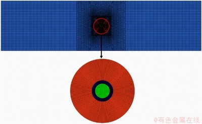
图1 CFD模型网格划分示意图
Fig. 1 Schematic diagram of mesh schemes applied in CFD mode
采用CFD模型仿真上述等效模型,需数值求解如下方程[24-25]。
连续方程:
 (1)
(1)
式中:v为速度矢量。
动力学方程:
 (2)
(2)
式中,t为时间;f是作用于单位质量上的向量力;ρ为流体密度;p为压力;μ为流体黏性系数。
能量方程:
 (3)
(3)
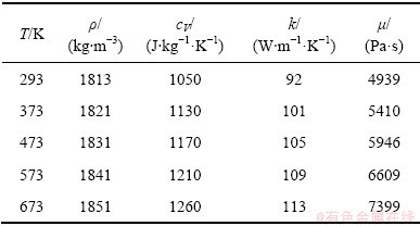
式中:cV为比定容比热容;T为温度;q为热流密度;k为导热系数;Φ为黏性耗散函数。式(2)、(3)中所用AZ31镁合金物性参数如表1所示[26-27]。
将与搅拌头接触的板件部分视为热加载区,即轴肩、搅拌针侧面和搅拌针底面。将轴肩与搅拌针区域的热源视为面热源。模型假设热量全部由摩擦产生,且全部流入板件和搅拌头。
模型中初始温度和环境温度设为室温(300 K)。根据实际焊接实验,板件的上下表面及侧面与金属夹具接触,散热较快,设置为对流换热边界,对流换热系数取为200 W/(m2・K),板上表面位于焊缝区域的面网格与空气接触,对流换热系数为30 W/(m2・K)[28]。
对焊速60 mm/min,转速分别为1000、1200、1400和1600 r/min工况下,板件从二层增材至五层过程,材料流动、温度、应变率变化规律进行仿真分析。上述模型在ANSYS Fluent软件环境下建立和求解。相关边界条件与材料属性由C语言编译的子程序定义(UDF)。采用瞬态求解器,增材时间设置为90 s。
表1 AZ31镁合金的热物理性能
Table 1 Thermal properties of AZ31 magnesium alloy
1.2 晶粒尺寸与硬度预测
Zener-Hollomon参数是表征材料经历热变形加工的常数,可表征温度、应变率对材料加工过程的影响。其定义式为[29]
 (4)
(4)
FSAM对镁合金材料的增材处理过程,可视同对增材区材料进行的热加工过程。结合CFD模型的计算结果,可等效计算增材区不同位置处材料经历的Z参数值。式中: 为等效应率张量;Q为再结晶激活能,取值135 kJ/mol[29];R为摩尔气体常数,取为8.314 J/mol・K[30];T为温度,取为计算位置处的最高温度。式中等效应变率张量[31]由材料流动速度与位移计算得到:
 (5)
(5)
式中:ui、uj分别为直角坐标系xi、xj方向的速度分量,计算Z值时取搅拌区经历的最大应变速率值。
大量实验观测表明,再结晶晶粒尺寸的自然对数与Z参数的自然对数呈线性关系。通过Zener-Hollomon参数,可以预测FSAM过程中形成的再结晶组织晶粒尺寸大小[32]:
 (6)
(6)
式中:d为再结晶晶粒尺寸(μm);k、b均为常数,分别取值为-0.1、6。
再结晶细化晶粒尺寸确定的基础上采用关联平均晶粒尺寸与力学性能的Hall-Petch[33]公式可进一步预测材料的显微硬度:
 (7)
(7)
式中:H0、kH均为常数;d为再结晶晶粒尺寸(μm)。
式(6)、(7)参数取值参考SERAJZADEH等[32]研究结果及本文转速1000 r/min、焊速60 mm/min工况下三层板FSAM实验硬度值测量结果确定。
2 实验
采用台式搅拌摩擦焊接设备对AZ31镁合金薄板件搅拌摩擦增材进行研究。搅拌头与板件几何尺寸和数值模型相同。实验选取的参数如下:转速1000、1200、1400和1600 r/min,焊速60 mm/min,搅拌头倾角1.5°,轴肩下压量0.1 mm。采用上述参数对板件进行一至二层、二至三层增材实验。增材前对构件表面进行打磨去氧化物处理,每增一层后对表面去毛刺处理。
采用K型热电偶对转速1400 r/min、焊速60 mm/min工况下,二至三层AZ31镁合金工件FSAM过程的测点温度进行测量。测点位置及温度测量结果如图2所示。实验观测点与相同位置仿真结果温升趋势一致,历程形态相同,最大误差为12.1%,在一定误差范围内证明了数值模型的准确性与有效性。图2中,数值预测结果低于实验结果,原因是CFD模型模拟过程中未模拟搅拌头对板的预热过程。图3所示为转速分别为1000、1200、1400和1600 r/min,焊速为60 mm/min工况下三层板增材试件的宏观形貌。随着转速的提高,焊缝表面成型良好,宏观形貌并无较大差异。
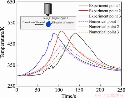
图2 试样上表面热电偶温度测量结果
Fig. 2 Temperature measurement results on top surface by thermo comple
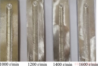
图3 FSAM试样照片
Fig. 3 Photos of FSAM samples
从垂直于搅拌区焊缝方向切取转速1000 r/min、焊速60 mm/min工况三层板FSAM试样,经镶样处理后,打磨、抛光至0.2 μm粗糙度。采用136°四面体金刚石压头,加载0.98 N试验力,保持8 s,测得维氏硬度值。为保证焊缝区平均晶粒尺寸的测量精度,对每层板件距板底部1 mm处选取测点,测点间距为0.5 mm。维氏硬度测点位置如图4所示。
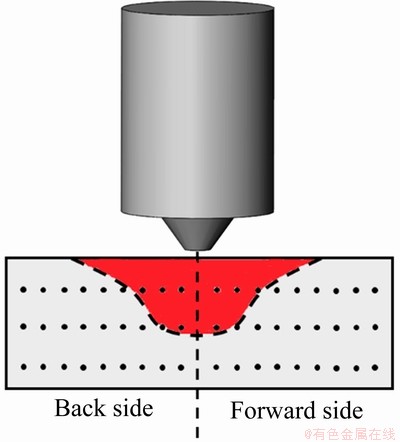
图4 FSAM试样横截面硬度测点位置
Fig. 4 Locations for hardness tests of FSAM sample
3 结果与分析
3.1 FSAM数值模拟宏观结果
增材过程中,搅拌针插入后热源开始产热,热输入增加,板件升温,由于滑动摩擦产热保持相对恒定,而热量散失速率随温度升高而增加,故一段时间后温度达到最高值。而冷却阶段没有热输入,并且伴随热量散失,因此,结构温度下降,温度降至室温后再进行下层板件增材。随着增材板件层数的增加,流入板件的热量保持恒定,温度会再次升高,但是由于单位体积内热输入下降,因而无法达到前一次温度最高值。
在搅拌摩擦增材成型过程,多种工艺参数均会对增材区温度分布产生影响,进而影响增材成型过程。根据热源模型,当搅拌头转速提高,搅拌头各部分产热功率增加,从而导致温度上升。为了研究转速对板件温度分布的影响,分别提取了焊速为60 mm/min,转速为1000、1200、1400和1600 r/min工况、三层板增材时,距板底部1 mm横截面温度分布云图如图5(a)所示。从图5(a)可以看出,随着搅拌头转速的提高,板件温度呈上升趋势。当焊速为60 mm/min,转速1000 r/min时,该横截面最高温度为496.09 K;转速1600 r/min时,该横截面最高温度为606.79 K。
在一定范围内,材料流动速度越大,材料流动越充分,板件增材成型效果越好。搅拌头旋转加剧周围材料流动,该区域材料受轴肩影响较大,流动速度远大于板边缘材料流动速度。随着增材板件层数增加,板件总体厚度超过搅拌针长度,搅拌针长度相对整个增材板件结构总体厚度较小,但是热影响区大小并没有发生改变。因此,工艺参数保持不变时,材料流动速度随增材板件层数几乎不产生变化,主要由增材工具几何尺寸决定。为研究搅拌头转速对材料流动速度的影响,分别选取转速1000 r/min、焊速60 mm/min,不同增材板件层数的情况下,垂直于焊缝方向,距离轴肩外缘0.5 mm处纵向截面上材料流动速度分布云图如图5(b)所示。不同增材板件数目下,材料流速最大值几乎相同,流速最大值均出现于轴肩外缘处。搅拌区材料流速较大,搅拌区外部几乎不发生材料流动。根据预测的横截面材料流动分布,可估算FSAM过程中的搅拌区域范围,即能划分增材影响区域,进而对增材影响区域的显微性能进行预测。
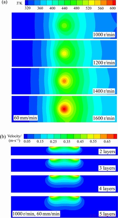
图5 模型预测温度场与材料流变
Fig. 5 Predicted results of temperature distribution(a) and materials flow field(b)
3.2 显微性能预测
增材影响区域动态再结晶过程造成晶粒细化,从而导致硬度值改变。为验证预测模型准确性,本文在对转速1000 r/min、焊速60 mm/min工况下,对三层板FSAM增材试样垂直于焊缝方向硬度值进行测量,结果如图6(a)所示。基于CFD模型,沿流线提取FSAM应变率计算结果如图6(b)所示。测量结果表明,焊缝中心位置硬度值低于距焊缝较远处,前进侧硬度均值79.50HV,后退侧硬度均值71.68HV,较前进侧的低10.91%。由数值模拟结果可知,后退侧材料应变率低于前进侧,动态再结晶过程没有前进侧充分,发生不完全动态再结晶,从而前进侧晶粒尺寸小于后退侧,因此,后退侧显微硬度均值低于前进侧。沿流线提取应变率及温度结果,采用式(5)~(7),预测增材区晶粒尺寸。结合晶粒尺寸预测结果及实验所测硬度(Hv),确定式(7)中的常数:
 (8)
(8)
由后退侧至前进侧,材料的应变率呈逐渐增大的趋势,这是因为前进侧的材料流动至搅拌针周围产生绕流,导致材料应变率增加。提取FSAM温度计算结果,基于Zener-Hollomon参数预测增材影响区材料晶粒尺寸,分布规律如图6(c)所示,增材区前进侧晶粒尺寸小于后退侧,这是因为增材区前进侧材料应变率高于后退侧,动态再结晶过程更加充分,导致晶粒更细。增材区显微硬度预测结果如图6(d)所示,增材区后退侧硬度均值小于前进侧,与实验测量结果规律一致。前进侧硬度均值为71.29HV,较实验结果相比,最大误差为10.33%;后退侧硬度均值为71.11HV,较实验结果相比,误差为0.79%,验证了模型的准确性与有效性。
图7所示为转速1000 r/min、焊速60 mm/min工况下,二层板FSAM过程增材区晶粒尺寸及显微硬度预测结果。结合三层板FSAM过程增材区显微性能预测结果分析知,随着增材板件数目增加,增材区平均晶粒尺寸减小,平均硬度增大。转速1000 r/min、焊速60 mm/min工况下,二层板FSAM过程增材区平均晶粒尺寸预测结果为11.11 μm,三层板FSAM增材区平均晶粒尺寸预测结果为8.37 μm,当板件层数增加时,FSAM晶粒尺寸减小24.7%。该工况下,二层板FSAM过程增材区显微硬度预测结果均值为68.00HV,三层板FSAM过程增材区显微硬度预测结果均值为71.20HV,相比于二层板FSAM增材区平均硬度值增大4.71%。
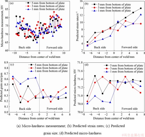
图6 三层板增材实验与数值结果
Fig. 6 Measured and predicted results of 3 layer-plates
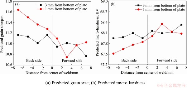
图7 二层板增材显微预测结果
Fig. 7 Micro prediction results of 2 layer-plates
FSAM过程中AZ31镁合金经历动态再结晶过程,导致晶粒细化,晶粒尺寸下降。但随搅拌头转速增大,晶粒尺寸呈增大趋势,这是因为转速增大时输入板件的热量增加从而导致材料过热,动态再结晶过程充分,且母材晶粒破坏,晶粒生长程度更高。材料显微硬度随晶粒尺寸的增大而减小,因此,随转速增大,材料显微硬度最终呈下降趋势。三层板FSAM过程,距板底部1 mm处截面,材料的平均应变率、晶粒尺寸、显微硬度随转速变化的预测规律如图8所示(图中取点间隔为10 mm)。
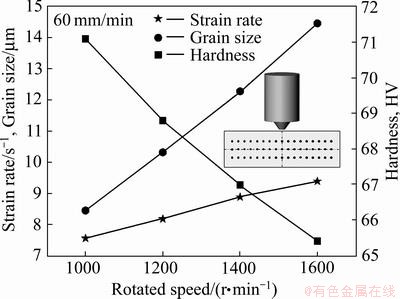
图8 平均应变率、晶粒尺寸和显微硬度随转速变化规律
Fig. 8 Average strain rates, grain sizes and micro-hardness in different cases
4 结论
1) 实验观测点与仿真温度结果的规律一致,验证了该CFD模型可准确、高效模拟搅拌摩擦增材制造过程。数值模拟计算结果表明,随搅拌头转速的增大,板件温度升高,材料流动速度增大,应变率增大。
2) 通过计算增材区域AZ31镁合金材料热变形过程Zener-Hollomon参数可以预测增材区域再结晶晶粒尺寸。预测结果表明,增材区前进侧材料动态再结晶过程更加充分,晶粒细化更加严重,因此前进侧晶粒尺寸小于后退侧;增材区前进侧显微硬度高于后退侧,三层板FSAM试样硬度值测量结果表明,转速1000 r/min、焊速60 mm/min工况下,前进侧硬度均值79.50HV,后退侧硬度均值71.68HV,较前进侧低10.91%。
3) 结合焊速60 mm/min,转速1000 r/min工况下,显微硬度实验测量结果,提出FSAM搅拌区再结晶组织显微硬度的快速预测公式。通过该公式计算出材料的显微硬度与实验结果大致吻合,最大误差为10.33%。
4) 随增材板件数目增加,增材区平均晶粒尺寸减小,转速1000 r/min、焊速60 mm/min工况下,二层板FSAM过程增材区平均晶粒尺寸预测结果为11.11 μm,三层板FSAM增材区平均晶粒尺寸预测结果为8.37 μm;当板件层数增加时,预测结果表明热影响区平均硬度值增大。
5) 快速预测公式结果表明,随搅拌头转速的增大,增材区材料的应变率、晶粒尺寸都呈逐渐增大的趋势,材料的显微硬度呈下降趋势。
REFERENCES
[1] CHANG J K, HE J K, MAO M, ZHOU W X, LEI Q, LI X, LI D C, CHUA C K, ZHAO X. Advanced material strategies for next-generation additive manufacturing[J]. Materials, 2018, 11(1): 166-185.
[2] YANG Y, SONG X, LI X J, CHEN Z Y, ZHOU C, ZHOU Q F, CHEN Y. Recent progress in biomimetic additive manufacturing technology: from materials to functional structures[J]. Advanced Materials, 2018, 30(36): 1706539-1706573.
[3] QIN L L, CHEN C J, ZHANG M,YAN K, CHENG G P, JING H M, WANG X N. The microstructure and mechanical properties of deposited-IN625 by laser additive manufacturing[J]. Rapid Prototyping Journal, 2017, 23(6): 1119-1129.
[4] LEARY M, PIOLA R, SHIMETA J,TOPPI S. Additive manufacture of anti-biofouling inserts for marine applications[J]. Rapid Prototyping Journal, 2016, 22(2): 416-434.
[5] DEAN D, MOTT E, LUO X Y, BUSSO M, WANG M O, VORWALD C, SIBLANI A, FISHER J P. Multiple initiators and dyes for continuous Digital Light Processing (cDLP) additive manufacture of resorbable bone tissue engineering scaffolds[J]. Virtual and Physical Prototyping, 2014, 9(1): 3-9.
[6] PALANIVEL S, NELATURU P, GLASS B, MISHRA R S. Friction stir additive manufacturing for high structural performance through microstructural control in an Mg based WE43 alloy[J]. Materials & Design, 2015, 65: 934-952.
[7] SHARMA A, BANDARI V, ITO K,KOHAMA K, RAMJI M, SAI B V H. A new process for design and manufacture of tailor-made functionally graded composites through friction stir additive manufacturing[J]. Journal of Manufacturing Processes, 2017, 26: 122-130.
[8] PALANIVEL S, SIDHAR H, MISHRA R S. Friction stir additive manufacturing: Route to high structural performance[J]. JOM, 2015, 67(3): 616-621.
[9] 王忻凯. 铝合金搅拌摩擦增材制造工艺研究[D]. 南昌: 南昌航空大学, 2015: 1-72.
WANG Xin-kai. Process study on aluminum alloy by friction stir additive manufacturing[D]. Nanchang: Nanchang Hangkong University, 2015: 1-72.
[10] SRIVASTAVA M, RATHEE S, MAHESHWARI S, SIDDIQUEE A N, KUNDRA T K. A review on recent progress in solid state friction based metal additive manufacturing: friction stir additive techniques[J]. Critical Reviews in Solid State and Material Sciences, 2019, 44(5): 345-377.
[11] MAO Y Q, KE L M, HUANG C P, LIU F C, LIU Q. Formation characteristic, microstructure, and mechanical performances of aluminum-based components by friction stir additive manufacturing[J]. The International Journal of Advanced Manufacturing Technology, 2016, 83(9): 1637-1647.
[12] DILIP J J S, RAFI H K, RAM G D J. A new additive manufacturing process based on friction deposition[J]. Transactions of the Indian Institute of Metals, 2011, 64(1/2): 27-30.
[13] YU H Z, JONES M E, BRADY G W, GRIFFITHS R J, GARCIA D, RAUCH H A, COX C D,HARDWICK N. Non-beam-based metal additive manufacturing enabled by additive friction stir deposition[J]. Scripta Materialia, 2018, 153: 122-130.
[14] LI D, YANG X, CUI L. Fatigue property of stationary shoulder friction stir welded additive and non-additive T joints[J]. Science and Technology of Welding and Joining, 2015, 20(8): 650-654.
[15] PAN F, XU A, DENG D, YE J H, JIANG X Q, TANG A T, RAN Y. Effects of friction stir welding on microstructure and mechanical properties of magnesium alloy Mg-5Al-3Sn[J]. Materials & design, 2016, 110(15): 266-274.
[16] LIU F C, MA Z Y. Influence of tool dimension and welding parameters on microstructure and mechanical properties of friction-stir-welded 6061-T651 aluminum alloy[J]. Metallurgical and Materials Transactions A, 2008, 39(10): 2378-2388.
[17] ROBSON J D, CAMPBELL L. Model for grain evolution during friction stir welding of aluminum alloys[J]. Science and Technology of Welding and Joining, 2010, 15(2): 171-176.
[18] DARRAS B M. A model to predict the resulting grain size of friction-stir-processed AZ31 magnesium alloy[J]. Journal of Materials Engineering and Performance, 2012, 21(7): 1243-1248.
[19] NASER A, DARRAS B. Micro-hardness prediction of friction stir processed magnesium alloy via response surface methodology[J]. Multidiscipline Modeling in Materials and Structures, 2017, 13(3): 377-390.
[20] ZHANG Z, LIU Y L, CHEN J T. Effect of shoulder size on the temperature rise and the material deformation in friction stir welding[J]. International Journal of Advanced Manufacturing Technology, 2009, 45(9/10): 889-895.
[21] SONG G, BOWLES A L, STJOHN D H. Corrosion resistance of aged die cast magnesium alloy AZ91D[J]. Materials Science and Engineering A, 2004, 366(1): 74-86.
[22] PADMANABAN G, BALASUBRAMANIAN V. Optimization of pulsed current gas tungsten arc welding process parameters to attain maximum tensile strength in AZ31B magnesium alloy[J]. Transactions of Nonferrous Metals Society of China, 2011, 21(3): 467-476.
[23] ZENG X, WANG Y, DING W, LUO A A, SACHDEV A K. Effect of strontium on the microstructure, mechanical properties, and fracture behavior of AZ31 magnesium alloy[J]. Metallurgical and Materials Transactions A, 2006, 37(4): 1333-1341.
[24] 苏铭德, 黄素逸. 计算流体力学基础[M]. 北京:清华大学出版社, 1997: 12-32.
SU Ming-de, HUANG Su-yi. Fundamentals of computational fluid dynamics[M]. Beijing: Tsinghua University Press, 1997: 12-32.
[25] 林建忠, 阮晓东, 陈邦国, 王建平, 周 洁, 任安禄. 流体力学[M]. 北京: 清华大学出版社, 2005: 96-114.
LIN Jian-zhong, RUAN Xiao-dong, CHEN Bang-guo, WANG Jian-ping, ZHOU Jie, REN An-lu. Fluid dynamics[M]. Beijing: Tsinghua University Press, 2005: 96-114.
[26] 管仁国, 赵占勇, 陈礼清, 王付兴. AZ31镁合金型材连续流变挤压成型过程的数值模拟[J]. 中国有色金属学报, 2010, 20(5): 923-929.
GUAN Ren-guo, ZHAO Zhan-yong, CHEN Li-qing, WANG Fu-xing. Numerical simulation of continuous rheo-extrusion process of AZ31 alloy[J]. The Chinese Journal of Nonferrous Metals, 2010, 20(5): 923-929.
[27] 方 静, 蒋 斌. AZ31镁合金铸锭加热过程中的温度场模拟[J]. 材料导报, 2007, 21(5): 365-367.
FANG Jing, JIANG Bin. Simulation on the temperature field during heating process of AZ31 ingots[J]. Material Review, 2007, 21(5): 365-367.
[28] 肖毅华, 张浩锋. 6061-T6铝合金搅拌摩擦焊温度场的数值模型和参数影响分析[J]. 机械科学与技术, 2017, 36(1): 119-126.
XIAO Yi-hua, ZHANG Hao-feng. Numerical model and influence analysis of parameters for temperature field in friction stir welding of 6061-T6 aluminum alloy[J]. Mechanical Science and Technology for Aerospace Engineering, 2017, 36(1): 119-126.
[29] CHANG C I, LEE C J, HUANG J C. Relationship between grain size and Zener-Holloman parameter during friction stir processing in AZ31 Mg alloys[J]. Scripta Materialia, 2004, 51(6): 509-514.
[30] ESSADIQI E, LIU W J, KAO V, YUE S, VERMA R. Recrystallization in AZ31 magnesium alloy during hot deformation[J]. Materials Science Forum, 2005, 475/479: 559-562.
[31] ARORA A, ZHANG Z, DE A, DEBROY T. Strains and strain rates during friction stir welding[J]. Scripta Materialia, 2009, 61(9): 863-866.
[32] SERAJZADEH S, TAHERI A K. An investigation on the effect of carbon and silicon on flow behavior of steel[J]. Materials & Design, 2002, 23(3): 271-276.
[33] FURUKAWA M, IWAHASHI Y, HORITA Z, NEMOTO M, TSENEV N K, VALIEV R Z, LANGDON T. Structural evolution and the Hall-Petch relationship in an Al-Mg-Li-Zr alloy with ultra-fine grain size[J]. Acta Materialia, 1997, 45(11): 4751-4757.
Simulation of friction stir additive process and its micro-properties prediction
LI Ru-qi, WU Qi, LONG Lian-chun
(Faculty of Materials and Manufacturing, Beijing University of Technology, Beijing 100124, China)
Abstract: The friction stir additive manufacturing (FSAM) is a new solid-state manufacture technology. The re-stirring process is a remarkable feature of FSAM. Under the action of severe deformation and thermal coupling, the grains of base metal were crushed and refined layer by layer to form a new recrystallized structure, and finally an additive forming component was formed. AZ31 magnesium alloy sheet for FSAM process was taken as the research object. Firstly, computational fluid dynamics model of FSAM was established. The influence of rotation speed on material rheology, temperature field and strain rate was studied, and compared with the experimental results. Secondly, the Zener-Hollomon parameters of the hot deformation process of the magnesium alloy material in the additive zone were calculated. Then, the Z parameters and the recrystallized grain size of in additive zone were correlated by empirical formula method. Finally, combined with the micro-hardness test results at 1000 r/min, a fast prediction algorithm for the recrystallized microstructure of the FSAM was proposed. The results indicate that, with the increase of layers, the average grain size and the average hardness in the additive zone decrease. With the increase of the rotation speed, the strain rate and recrystallized grain size of the material in the additive zone gradually increase, but the micro-hardness shows a downward trend.
Key words: friction stir additive manufacturing; numerical simulation; grain size; micro-hardness
Foundation item: Project(2018M641128) supported by China Postdoctoral Science Foundation; Project(2018YFB0703502) supported by the National Basic Research Development Program of China; Project(ZZ2019-129) supported by the Beijing Postdoctoral Research Foundation, China; Project(ykj-2018-00264) supported by the Beijing University of Technology Program, China
Received date: 2019-09-19; Accepted date: 2019-11-19
Corresponding author: WU Qi; Tel: +86-13621242110; E-mail: qiwu@bjut.edu.cn
(编辑 龙怀中)
基金项目:中国博士后科学基金资助项目(2018M641128);国家重点研发计划资助项目(2018YFB0703502);北京市博士后科研活动经费资助项目(ZZ2019-129);北京工业大学研究生科技基金资助课题(ykj-2018-00264)
收稿日期:2019-09-19;修订日期:2019-11-19
通信作者:吴 奇,讲师,博士;电话:13621242110;E-mail:qiwu@bjut.edu.cn

