J. Cent. South Univ. (2012) 19: 2238-2246
DOI: 10.1007/s11771-012-1268-y
Vibration-based feature extraction of determining dynamic characteristic for engine block low vibration design
DU Xian-feng(���ܷ�), LI Zhi-jun(��־��), BI Feng-rong(�Ϸ���),
ZHANG Jun-hong(�ſ���), WANG Xia(��ϼ), SHAO Kang(�ۿ�)
State Key Laboratory of Engines (Tianjin University), Tianjin 300072, China
? Central South University Press and Springer-Verlag Berlin Heidelberg 2012
Abstract: In order to maintain vibration performances within the limits of the design, a vibration-based feature extraction method for dynamic characteristic using empirical mode decomposition (EMD) and wavelet analysis was proposed. The proposed method was verified experimentally and numerically by implementing the scheme on engine block. In the implementation process, the following steps were identified to be important: 1) EMD technique in order to solve the feature extraction of vibration signals; 2) Vibration measurement for the purpose of confirming the structural weak regions of engine block in experiment; 3) Finite element modeling for the purpose of determining dynamic characteristic in time region and frequency region to affirm the comparability of response character corresponding to improvement schemes; 4) Adopting a feature index of IMF for structural improvement based on EMD and wavelet analysis. The obtained results show that IMF of signal is more sensitive to response character corresponding to improvement schemes. Finally, examination of the results confirms that the proposed vibration-based feature extraction method is very robust, and focuses on the relative merits of modification and full-scale structural optimization of engine, together with the creation of new low-vibration designs.
Key words: feature extraction; dynamic characteristic; finite element model; empirical mode decomposition; diesel engine block
1 Introduction
The demands of customers regarding the quality level of automobile vehicles are constantly increasing. From the view of NVH (noise, vibration and hashness), most of the vibrations generated by the engine are consequences of the engine��s own design [1], so it is necessary to assure the structural weak regions which could increase the vibration level of the engine in the design process. Dynamic characteristic is one of the valid parameters in monitoring the state or in determining the weak regions of diesel engine structures, and the combination method of experiment and simulation can effectively reduce the product development time. In order to achieve the low vibration design of engine block, we should introduce one feature extraction method for determining dynamic characteristic based on the experiment and simulation.
The representative methods in time-frequency domain are Wigner�CVille distribution [2] and wavelet transform [3-5]. Wavelet analysis has been widely applied to non-stationary signals analysis in recent years [6]. Among these methods, wavelet analysis has been found to have powerful capability in engine feature extraction, because it is able to represent signals in the time-frequency plane with better resolution compared to others. However, the wavelet analysis is essentially a kind of Fourier transform with adjustable windows and has its limitations. The limitations displayed as follows: There is no uniform criterion for the selection of an appropriate mother wavelet function for feature extraction. The selection of a mother wavelet is mostly based on the similarity between wavelet function and impulses generated by engine, and it is often based only on an analyst��s intuition and experience.
Feature extraction based on vibration analysis has been studied extensively, based on the assumption that each signal consists of many simple intrinsic modes of oscillation. HUANG et al [7-8] proposed a new signal processing tool called EMD. EMD is able to process a vibration signal self-adaptively based on the characteristics of the raw signal in the time domain. The self-adaptation means that the analysis results are not affected by some basic functions such as the sinusoidal function in Fourier transforms and the mother wavelet in wavelet analysis. For a measured vibration signal, empirical mode decomposition (EMD) performs a time adaptive decomposition of the signal into elementary, almost orthogonal, components [9]. Therefore, each intrinsic mode function (IMF) may contain the principal information related to a specific component in the machine. Some research results on machine feature extraction using EMD have been published recently [10-13]. Therefore, early engine fault detection using vibration signal feature extraction techniques benefits the decision-making and maintenance-planning process, which will in turn decrease maintenance costs and production costs, and prevent accidents.
From a manufacturing point of view, it is necessary to assure the structural weak regions which could increase the vibration level of engine. Different parameters and locations adopted could create considerable variations regarding vibration performances from the original design. In order to determine certain points for measuring the level of vibration through a short test, a measurement procedure is established to monitor vibration in this work. Therefore, vibration response of engine block is obtained, using experiment and simulation, which is compared to affirm the comparability of response character.
A simulation of structural optimization for the engine block is proposed. It is hard to optimize the shape of a component using the actual design variables like dimension of a component. In this work, the shape vectors of morphing technology takes an finite element (FE) model as design variable for dynamic response analysis of engine block.
2 Vibration response of engine block
In order to realize the improvement schemes for complex structures using extracted response feature index based on EMD, it is necessary to acquire in advance the multitudinous vibration response signal of complex structures with different improvement schemes. It is feasible to get vibration signal for a practical diesel engine block structures with various improvement schemes only using experimental measurement. However, it is not realistic to let a practical block structure experience all kinds of improvement schemes. The feasible and effective approach is to obtain the structural vibration response signal with various possible improvement schemes through numerical simulation. For this purpose, a structural dynamic model is established through vibration analysis theory and finite element method. Thus, structural improvement feature can be obtained before the actual structural improvement schemes finished.
It is assumed that vibration amplitude of engine block is small so that structure is a linear vibration system. Then, equation of motion of a structure can be written as
 (1)
(1)
where 
 and x are the vectors of structural acceleration, velocity and displacement, respectively; M and K are the global mass and stiffness matrices, which are established using finite element method; and F(t) is the excitation force vector; g indicates structural improvement status. If structural improvement is local and very small, it may be a comprehensible supposition that the improvement only affects local engine characters of structures. Then, it is feasible to assume that small local improvement schemes merely affect local engine characters of structures, then the changes of engine characters only occur in one or a few elements around the improvement elements of finite element model of engine block structures, but engine characters of other elements keep unchanged. Therefore, one can utilize small change of the element stiffness with improvement to indicate small improvement of structures, thus, the global stiffness matrix K(g) will vary with improvement status g. Generally, structures with small improvement schemes does not accompany with the increase or decrease of structural mass. Thus, assume the mass matrix M is unchangeable in finite element model of improvement structures. C(g) is global damping matrix, which is related to improvement status g. Since the materials of engine block generally have large damping, their influence on the change of modal resonance is not negligible. However, calculation of practical damping matrix is very complicated and difficult. For structural vibration with small displacement, one of the feasible methods is to adopt the assumption of proportional damping. Then, the damping matrix can be denoted as
 (2)
(2)
where �� and �� are the proportional coefficients to be determined.
Equation (1) can be translated into the state governing equations as
 (3)
(3)
where  is a determinated and contrived
excitation imposed on structures in order to get structural dynamic responses. Therefore, f(t) and A=
 are known for a given improve-
ment status of structures. One can simulate the structural vibration responses numerically using the commercial software.
Structural vibration responses depend on structural natural frequency, damping, stiffness and exciting condition. On the other hand, various improvement schemes in a structure will cause more or less variance of these structural parameters. Therefore, many vibration parameters, such as natural frequency, mode shape, modal damping, can be used to determine structual improvement status. However, some studies [14-15] have shown that structural modal parameters are not sensitive to small improvement, and therefore this method may not be suitable to determine the improvement effect in various engineering structures. In this work, enough ribs should be adopted to improve the vibration performance of diesel engine block.
Some kinds of structural improvement indexes based on EMD are extracted. In order to extract the structural improvement information from its dynamic response signals, the signals are firstly decomposed into multiple IMFs using EMD. Hence, the total energy in the original signals can be distributed into all IMFs. By comparing the instantaneous frequencies corresponding to IMFs of orignal structures and those of improvement structures, it can be found that some instantaneous frequencies change obviously. Based on this fact, the combination method of EMD and wavelet analysis defined as follows is used for improvement determinition in this work.
3 Feature extraction based on EMD and wavelet analysis
In general, the vibration signals collected from the diesel engine block are non-stationary and nonlinear. It is beneficial to acquire adaptively the frequency-time distribution of the amplitude between the time and frequency domains of different vibration signals from various improvement schemes in engine structures. The vibration signals, depending on its complexity, may have many different coexisting modes of oscillation at the same time. Each of these oscillatory modes is represented by an intrinsic mode function (IMF) with the following definitions: 1) In the whole data set, the number of extreme and the number of zero-crossings must either be equal or differ at most by one. 2) At any point, the mean value of envelop defined by local maxima and envelop defined by the local minima is zero.
The EMD is used to decompose a nonlinear non-stationary signal into a few IMFs, and then calculate the time-varying of each IMF referred instantaneous amplitude and referred instantaneous frequency. EMD is a data-driven signal decomposition technique that sequentially extracts zero-mean IMFs from a signal, starting from high-frequency to low-frequency. EMD is used to sequentially decompose a signal x(t) into n IMFs ci(t) and a residual rn as
 (4)
(4)
where c1 has the shortest characteristic time scale and is the first extracted IMF. The characteristic time scale of c1 is defined by the time lapse to the extreme of x. Once the extrema are identified, compute the upper envelop and lower envelop using natural cubic spline, subtract the mean of the upper and lower envelops from the signal, and then treat the residuary signal as a new signal. Repeat these steps for many times until the left signal has a pair of symmetric envelops.
After decomposing the signal by EMD method, then extract the feature parameters from instantaneous frequency of signals. But the general signal x(t) does not satisfy the demand of frequency signal on narrow band. So it needs to be dealt with EMD firstly, and then get the IMF components which satisfy the demand. The analytic instantaneous frequency of each IMF component is
 (5)
(5)
where ai(t) represents the instantaneous amplitude of x(t), ��i(t) is the physical meaning of instantaneous frequency of the signal x(t).
For the reason of the capability of accurate extraction of time-varying frequency and amplitude, EMD can be used for accurate noise filtering, feature extraction of nonlinear phenomena, and identification of nonlinear continuous systems. Although an IMF may be different from modal vibration function due to signal processing errors, EMD is probably the best approach at the present time for signal decomposition of nonlinear non-stationary signals [16-17]. In order to show the usefulness and advantage of the EMD method, the flow chart with a simulation is performed, which is shown in Fig. 1. We consider the simulation data as
 (6)
(6)
Figure 2(a) shows the FFT spectrum of the original signal f(t). It exactly reports the frequencies of the three components, but no time information about them occurs. In the time-frequency continuous wavelet transform (CWT) diagram of the signal f(t) shown in Fig. 2(b), both the frequencies and their locations can be viewed.
Therefore, combined with the good time-frequency distribution of wavelet analysis, the proposed method based on EMD and wavelet analysis makes it up. With application of the sifting process, we will obtain four IMF components, as shown in Fig. 3(a). The foregoing three IMFs possess prolific information. In order to improve frequency and time resolution at the same time, put wavelet transform into the first IMF.
Compared with the wavelet transform of simulation data, the application of EMD technique can extract the local vibration character information better. Figure 3(b) shows that both the frequencies and their locations can be viewed better at different frequency bands.
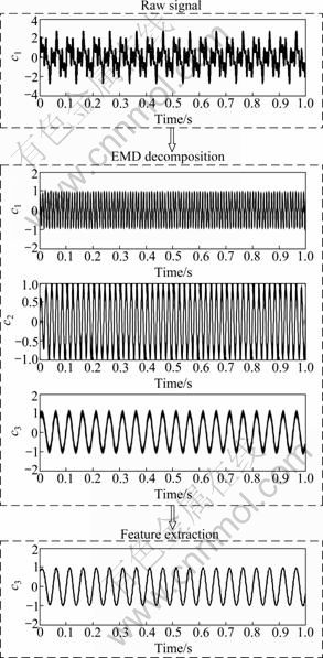
Fig. 1 Flowchart for feature extraction of EMD method
4 Experimental set-up
For the direct relationship between mechanical vibrations generated by the engine and noise emission exists, the vibration measurement is easier to fix and the measuring position can be set accurately and repeatedly, and it is also stronger against external noise.
4.1 Measurement point
It is necessary to carefully select the adequate position where the vibration accelerometer will pick up the vibration signal. In order to select the best location, some measurements on different points have been carried out and the results are compared later under the same test conditions.

Fig. 2 Spectrum (a) and CWT diagram (b) of signal f(t)
The recommended measuring position is shown in Fig. 4. In view of the layout and installation of engine, the sensor is fixed on the main structure of the diesel engine correctly, and then, it facilitates the location process. A cylinder block modal analysis has been made in order to find a sensor location, and the measuring positions should have sufficient stiffness so as to avoid local vibration modes, and allow good vibration transmissibility. Position has been selected as measurement point which is allocated on the block, marked with ��*�� symbol.
4.2 Test determination
The analysis was carried out on four-cylinder direct injection diesel engine, and the engine is installed on a special test bench with the necessary running facilities. Vibration sensor is then installed by screwing them to the block and the engine starts up. Afterwards, the engine is warmed up at a constant speed (800 r/min) until the water temperature reaches 85 ��.
Figure 5 illustrates the measurement chain used to acquire data regarding vibration. The signal from one piezoelectric accelerometer is measured. Through a magnetic pick-up, the engine speed and the top dead centre (TDC) position of first cylinder are collected. Then, through a digital signal processor (DSP) governed by a personal computer (PC), signals will be digitalized, processed and stored. The PC itself is in charge of controlling the engine��s working conditions and all parameters related to testing. For 10 s, the average of 1 024 temporal samples from the accelerometer, TDC and engine speed signals are acquired by the PC through the DSP card.

Fig. 3 EMD decomposition results of f(t) (a) and wavelet transform of first IMF namely c1 (b)

Fig. 4 Schematic layout of measurement point
5 Case studies
5.1 Feature extraction in experiment
From the simulation process above, we see that the EMD technique may be applied to obtain the vibration characteristics of diesel engine. Now, turn to the experiment verification. The acceleration signals at the engine block contain relatively more energy from high to low frequency band. Then EMD is adopted to obtain the IMF components, and obtain the instantaneous envelopment from each IMF in different frequencies and time scales.
An in-line four-cylinder diesel engine with speed of 1 800 r/min was used in this work. The sampling frequency was 2 048 Hz. Figure 6(a) shows the time domain waveform of an acceleration signal picked up from the surface of diesel engine block. Accordingly, the auto-power spectrum is given in Fig. 6(b). It is obvious that the main energy of the signal concentrates below the frequency 1 000 Hz without time information.
The frequencies of natural vibrations have low frequency and primary energy. The engine also has some frequency bands with low vibration energy which are not easy to distinguish from the complex vibration signal, as shown in Fig. 6(b).

Fig. 5 Procedure for measurement chain

Fig. 6 Acceleration signal of engine block (a) and auto-power spectrum of signal (b)
Using the EMD method firstly, the signal is decomposed into six IMF components, fimf1, fimf2, ��, fimf6 and a residue r. The six components are illustrated in Fig. 7, in which the residue r is omitted. Correspondingly, the wavelet transforms of fimf2 and fimf4 are shown in Fig. 8. From the results in Fig. 7, we can see that the EMD method acts as a set of filters and has decomposed the original vibration signal into six frequency bands. Components fimf1, fimf2 and fimf3 are the primary structure vibration energies of collected signal, and the main frequency bands are contained among these IMFs.
The ignition frequency is about 60 Hz with the engine rotating at 1 800 r/min. The time length of the signal calculated in this work is about 0.4 s. The results of fimf2 and fimf4 using the EMD technique are shown in Fig. 8. It can be seen that the IMFs around 60 Hz and 180 Hz which are multiples of the ignition frequency, vary with time. So, it can be easily seen that the vibration characteristic of engine is generated by the motion and excitation of engine components.
5.2 Feature extraction in finite element simulation
Since the response history data in the finite element simulation are free of any noise pollution, in other words, the finite element model of engine block represents the ideal cases, and vibration-based extraction is used to determine structural improvement which is treated between the original and improved engine block.
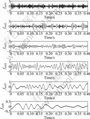
Fig. 7 Six IMF components of vibration signal
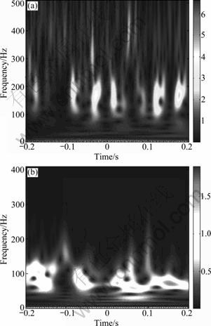
Fig. 8 Wavelet transforms of fimf2 (a) and fimf4 (b)
The three-dimensional model created by Pro/Engineer made some simplify to structures which have no large effect on the characteristics of engine block, but the major structure dimensions and shapes retain completely in order to have an accuracy correct finite element analysis. Then, define the same free boundary conditions and the properties of elements in the finite element model. Adopt the testlab produced by LMS company in the analysis of experiment, and obtain multi-point response of block through single-point excitated by hammer impact. The original finite element model of engine block is shown in Fig. 9(a), and Fig. 10 shows the comparison between the experiment and finite element modal analysis of engine block.

Fig. 9 FEM model of block: (a) Original block; (b) Improved block
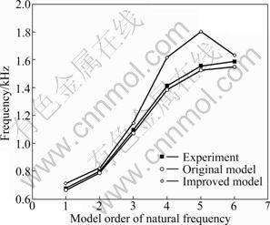
Fig. 10 Comparison between experiment and finite element modal analysis of engine block
The modal of diesel engine block is key factor for the vibration prediction of engine in the finite element and multi-body dynamics analysis. Figure 10 shows that the results of the experiment and finite element modals are in good similarity, which verifies the accuracy of the finite element model of engine block, provides the information of the load and time history for the kinetic analysis, and lays good foundations for the vibration prediction of engine block.
Regard the loads, such as the combustion explosion pressure, percussion piston force and main bearing force, to be the loading condition, and simulate the constraint according to the actual situation of the diesel [18]. The optimization of engine block is performed with the finite element model analysis.
Surface optimization is a type of conceptual design in finding the best layout of ribs in the production structure, and the purpose of the design is to alter the frequency, stiffness and structure shape through the defining of the location and appearance dimension. Surface optimization is performed to find a final optimum design shape, and the design variables for surface optimization are related to the design spaces. Using the experimental and simulation methods, the reasonableness of the improvement schemes is verified, which is determined by surface optimization.
The purpose of surface optimization is to enhance the whole engine block stiffness, decrease modal density, and reduce the vibration of engine block. The modal density for finite element block model is calculated. Lower density means that this contribution for structure is less, which can be removed. The results of this analysis assist designer to find essential areas from design areas. The optimization process is demonstrated as follows:
1) Definition of optimization
Areas modified in engine block surface optimization are defined in Fig. 9(a). The engine block is designed by the ribs, with the purpose for increasing the stiffness, decreasing the modal density and reducing the engine block velocity intensity. Objective of optimization is to minimize the vibration intensity, especially, decrease the amplitude of velocity in some special frequency bands.
2) Optimization results
Utilize the prediction of vibration, and regard the vibration severity as the final evaluation of the improved engine block. The original and improved models of engine block are shown in Fig. 9. The comparison between the original and improved modals of the engine block is shown in Fig. 10. The vibration velocity and intensity of the engine block are given in Table 1. The x, y and z directions represent the transverse, portrait and vertical directions of engine block, respectively, and vibration intensity is expressed as
 (7)
(7)
Table 1 Vibration intensity results of improved block
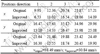
From the results of modal analysis and vibration velocity analysis corresponding to the original and improved engine blocks, it can be seen that the ribs enhance the block structural stiffness, increase the natural frequency of block modal, and decrease the vibration velocity of engine block.
As indicated by the results above, the main block frequency can be identified with no difficulty, and we can get each IMF change during the simulation process. The signals of original and improved engine blocks are shown in Figs. 11(a) and (b), respectively.
Figure 11 shows no obvious difference between the signals for these two engine blocks. Therefore, the signals of original are decomposed and engine blocks are improved by EMD method. This section is designed to explore if the EMD technique remains applicable for identifying frequencies changes in the signal processing process. To end, for the purpose of comparison, a comparison research of simulation results is conducted, and the comparison results of one component fimf2 are shown in Fig. 12. Accordingly, these IMFs are transformed using wavelet transform. The energy-time and frequency-time distributions of the IMFs are shown in Fig. 13.
In comparison with the Fourier spectrum of the IMFs shown above, block-related frequencies have been greatly enhanced by use of the EMD. The block frequency set can be clearly identified, and the amplitudes of special frequencies of engine are reduced effectively, especially for some frequency bands. We can further confirm for the structural weak regions and main vibration sources, IMFs show a good effect, which are beneficial to the engine block surface optimization. Each IMF should be considered to reduce the engine vibration, and define the design area of surface optimization.

Fig. 11 Signals of engine block: (a) Original block; (b) Improved block
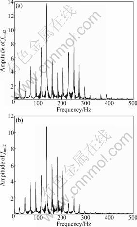
Fig. 12 Comparison of amplitude of fimf2: (a) Original block; (b) Improved block
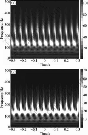
Fig. 13 Comparison of instantaneous frequencies of fimf2: (a) Original block; (b) Improved block
Figure 13 presents that some obvious changes between these two signals can be found, and this indicates that the signal energy of the IMFs is more sensitive to structural improvement. The results also prove that vibration-based feature extraction for determining structural improvement schemes based on EMD and wavelet analysis is reasonable and effective, and it can be used for improving engine block for lower vibration level target.
6 Conclusions
1) Vibration-based feature extraction based on EMD and wavelet analysis is proposed. The simulation and experiments demonstrate that the performance is ideal in signal processing.
2) The IMFs are adopted to reflect the dynamic characteristic of engine block. FFT and CWT are used to extract the information of each IMF, and the amplitude and signal energy are selected for the comparison.
3) The simulation of engine block verifies that feature extraction of determining dynamic characteristics can help to provide valuable information that can contribute towards the relationship between the improvements and weaknesses of engine block, allowing for rapid identification of the root cause of problems.
4) According to the analysis of vibration signals measured under improvement schemes with ribs, we can extend the method of vibration-based feature extraction to other improvement schemes with parameters variation.
References
[1] LEE N, PARK W, RUOTOLO R, TROMBLEY D. NVH development of EU5 2.0L and 2.2L diesel engine [C]// SAE 2011 World Congress and Exhibition. Detroit, MI, United States: SAE, 2011.
[2] WANG Y, JIANG Y C. New time-frequency distribution based on the polynomial Wigner-Ville distribution and L class of Wigner-Ville distribution [J]. IET Signal Processing, 2010,4(2): 130-136.
[3] YAN Z H, MIYAMOTO A, JIANG Z W. Frequency slice wavelet transform for transient vibration response analysis [J]. Mechanical Systems and Signal Processing, 2009, 23(5): 1474-1489.
[4] SHEEN Y T, HUNG C K. Constructing a wavelet-based envelope function for vibration signal analysis [J]. Mechanical Systems and Signal Processing, 2004, 18(1): 119-126.
[5] SUBASI A. Application of adaptive neuro-fuzzy inference system for epileptic seizure detection using wavelet feature extraction [J]. Computers in Biology and Medicine,2007, 37(2): 227-244.
[6] LOUTRIDIS S, DOUKA E, TROCHIDIS A. Crack identification in double-cracked beams using wavelet analysis [J]. Journal of Sound and Vibration, 2004, 277(4/5): 1025-1039.
[7] HUANG N E, SHEN Z, LONG S R, WU M L C, SHIH H H, ZHENG Q N, YEN N C, TUNG C C, LIU H H. The empirical mode decomposition and the Hilbert spectrum for nonlinear and non-stationary time series analysis [J]. Proceedings of the Royal Society of London Series, 1998, 454(1971): 903-995.
[8] HUANG N E. Review of empirical mode decomposition [J]. Wavelet Applications, 2001, 4391: 71-80.
[9] CHENG J S, YU D J, YANG Y. Research on the intrinsic mode function (IMF) criterion in EMD method [J]. Mechanical Systems and Signal Processing, 2006, 20(4): 817-822.
[10] LOUTRIDIS S J. Instantaneous energy density as a feature for gear fault detection [J]. Mechanical Systems and Signal Processing, 2006, 20(5): 1239-1253.
[11] WU Fang-ji, QU Liang-sheng. Diagnosis of subharmonic faults of large rotating machinery based on EMD [J]. Mechanical Systems and Signal Processing, 2009, 23(2): 467-475.
[12] DU Qiu-hua, YANG Shu-nian. Application of the EMD method in the vibration analysis of ball bearings [J]. Mechanical Systems and Signal Processing, 2007, 21(6): 2634-2644.
[13] PAREY A, EI BADAOUI M, GUILLET F, TANDON N. Dynamic modelling of spur gear pair and application of empirical mode decomposition-based statistical analysis for early detection of localized tooth defect [J]. Journal of Sound and Vibration, 2006, 294(3): 547-561.
[14] ZOU Y, TONG L, STEVEN G P. Vibration-based model-dependent damage identification and health monitoring for composite structures-A review [J]. Journal of Sound and Vibration, 2000, 230(2): 357-378.
[15] DIEBALA A, OUELAA N, HAMZAOUI N. Detection of rolling bearing defects using discrete wavelet analysis [J]. Meccanica, 2008, 43(3): 339-348.
[16] HUANG N E, WU M L, QU W D, LONG S R, SHEN S S P. Applications of Hilbert-Huang transform to non-stationary financial time series analysis [J]. Applied Stochastic Models in Business and Industry, 2003, 19(3): 245-268.
[17] LI He-long, DENG Xiao-yan, DAI Hong-liang. Structural damage detection using the combination method of EMD and wavelet analysis [J]. Mechanical Systems and Signal Processing, 2007, 21(1): 298-306.
[18] DU Xian-feng, LI Zhi-jun, BI Feng-rong, ZHANG Jun-hong, WANG Xia, SHAO Kang. Structural topography optimization of engine block to minimize vibration based on sensitivity analysis [J]. Advanced Materials Research, 2011, 291/292/293/294: 318-326.
(Edited by DENG L��-xiang)
Foundation item: Project(50975192) supported by the National Natural Science Foundation of China; Project(10YFJZJC14100) supported by Tianjin Municipal Natural Science Foundation of China
Received date: 2011-06-13; Accepted date: 2011-09-27
Corresponding author: BI Feng-rong, Associate Professor, PhD; Tel: +86-22-27401351; E-mail: fr_bi@tju.edu.cn

