TIG合金化制备AZ91镁合金表面Al-TiC涂层
来源期刊:中国有色金属学报(英文版)2020年第6期
论文作者:Chinmaya Kumar PADHEE Manoj MASANTA A. K. MONDAL
文章页码:1550 - 1559
关键词:AZ91镁合金;Al-TiC涂层;TIG合金化;显微硬度;干滑动磨损
Key words:AZ91 magnesium alloy; Al-TiC coating; TIG alloying; micro-hardness; dry sliding wear
摘 要:尝试以TIG电弧为热源,通过Al和TiC的混合物进行表面合金化以改善AZ91镁合金的表面性能。通过扫描电镜(SEM)和X射线衍射(XRD)分析AZ91合金层的显微组织演化。采用维氏显微硬度计和销-盘磨损试验分别研究显微硬度和干滑动磨损行为。结果表明,在一定的电流和扫描速度下,AZ91合金基体上形成近均匀的合金层。合金层的硬度值达305 HV0.25,与AZ91合金基体相比,合金层的磨损几乎可以忽略不计。
Abstract: An attempt was made to improve the surface properties of the AZ91 Mg alloy through surface alloying of a mixture of Al and TiC with the help of TIG arc as heat source. The microstructural evolution of the alloyed layer on the AZ91 alloy was analysed through SEM and XRD technique. The micro-hardness and the dry sliding wear behaviour were assessed by Vickers micro-hardness tester and pin-on-disc wear test setup, respectively. It is revealed that almost uniform alloyed layer forms on the AZ91 alloy substrate for a specific current and scan speed employed in the present experiments. The alloyed layer exhibits hardness value up to 305 HV0.25, and almost negligible wear as compared to the as-received AZ91 alloy substrate.
Trans. Nonferrous Met. Soc. China 30(2020) 1550-1559
Chinmaya Kumar PADHEE1, Manoj MASANTA1, A. K. MONDAL2
1. Department of Mechanical Engineering, National Institute of Technology Rourkela, Rourkela 769008, India;
2. Department of Metallurgical Engineering, Indian Institute of Technology (BHU) Varanasi, Varanasi 221005, India
Received 22 November 2019; accepted 30 April 2020
Abstract: An attempt was made to improve the surface properties of the AZ91 Mg alloy through surface alloying of a mixture of Al and TiC with the help of TIG arc as heat source. The microstructural evolution of the alloyed layer on the AZ91 alloy was analysed through SEM and XRD technique. The micro-hardness and the dry sliding wear behaviour were assessed by Vickers micro-hardness tester and pin-on-disc wear test setup, respectively. It is revealed that almost uniform alloyed layer forms on the AZ91 alloy substrate for a specific current and scan speed employed in the present experiments. The alloyed layer exhibits hardness value up to 305 HV0.25, and almost negligible wear as compared to the as-received AZ91 alloy substrate.
Key words: AZ91 magnesium alloy; Al-TiC coating; TIG alloying; micro-hardness; dry sliding wear
1 Introduction
Magnesium and its alloys are the lightweight materials with desirable properties like low density, high specific strength, excellent castability, machinability, and hot formability, which make them suitable candidates in automobile and aerospace industries [1]. The Mg alloys are also used in electronic industry as a replacement of plastic due to its electromagnetic shielding and damping capacity [2]. However, wider applications of Mg alloys are restricted in specific components because of their low hardness, poor wear and corrosion resistances. Henceforth, relevant research becomes essential on the alloying and surface treatment techniques to improve their surface properties.
Various surface treatment methods like laser surface melting, laser cladding, TIG cladding, plasma spraying, and micro-arc oxidation were employed to improve the hardness, wear and corrosion resistance of various graded Mg alloys [3-6]. Among them, laser surface modification technique achieved foremost attention owing to its superior control of heat source, and capability to produce strong metallurgical bond between the coating and the substrate material [2,7]. Several research groups have also attempted to modify the surface properties of various graded magnesium alloys by using different cladding or alloying techniques [8-10].
AZ91 magnesium alloy have received considerable attention due to its optimum combination of ambient temperature strength, ductility, and good die-castability [11]. To improve the wear resistance of AZ91 magnesium alloy, laser surface cladding with a mixture of Al and Si powder was investigated [12,13]. It was found that the surface hardness of the Mg alloy was increased from 35 HV to 170 HV after the laser treatment. LIU et al [14] deposited the Al-Al2O3 clad layer on AZ91 magnesium alloy by laser surface cladding route, which improved the micro-hardness and the wear resistance of the alloyed surface significantly. WANG et al [6] showed that incorporation of Al2O3 nano-particles on the ceramic coating developed on AZ91 alloy by micro-arc oxidation method resulted in high hardness and anti-corrosion property of the alloyed surface. ZHENG et al [4] revealed that the deposition of Al-SiC composite layer on AZ91 alloy by laser cladding method improved the hardness and sliding wear resistance of the alloy remarkably. Deposition of NiAl/Al2O3 coating on AZ91 alloy by laser cladding method has produced strong metallurgic bond between the NiAl, Al2O3 and the substrate material, and improved the surface properties of the AZ91 alloy expressively [15].
The literature revealed that the surface modification of Mg alloys was accomplished predominantly by laser cladding or alloying techniques. Nevertheless, high capital cost of the laser source and processing difficulties make the method expensive and complex. In addition, low absorption of laser beam by the Mg alloy, diminishes its efficiency and enhances the processing cost further. On the other side, tungsten inert gas (TIG) cladding has great potential to produce a thick coating by scanning the arc over the pre-deposited coating layer according to requirement [16-18]. In this regard, work of ELAHI et al [3], which demonstrated surface alloying of AZ91 alloy by TIG melting with Al-Ni powder mixture opened the possibility of TIG cladding method to produce a hard and wear- resistant coating on AZ91 alloy for specific application. TiC is a hard ceramic used as coating material in engineering components because of its high hardness, excellent wear resistance, high melting point and thermal stability [17,19]. Application of TiC as coating material for different types of steel by laser surface modification or TIG cladding method was received considerable attention [20,21]. However, use of TiC coating on magnesium alloy for the improvement of its hardness and wear resistance was hardly explored.
In this work, an attempt has been made to improve the surface properties of the AZ91 magnesium alloy through surface alloying with the help of TIG arc as heat source and applying a layer of Al-TiC powder mixture on the substrate surface. The microstructural evolution during the surface alloying was analysed through SEM images of the alloyed layer and XRD technique. The micro- hardness, and the wear characteristic of the alloyed layer were assessed by Vickers micro-indentation method and pin-on-disc type sliding wear test respectively.
2 Experimental
For the present investigation, a commercially pure gravity-cast AZ91 magnesium alloy (Mg-8.8Al-0.7Zn-0.2Mn) was used as substrate material. The alloy was cut to the dimension of 75 mm × 45 mm × 8 mm using a band saw with proper cooling arrangement. The substrate of the AZ91 alloy of specified dimension was then prepared by polishing with emery paper (220 grade), and subsequent cleaning in acetone. To prepare the alloying precursor, commercial TiC particles (average size of 5 μm) and pure Al powder (size range of 10-25 μm; purity of 99.5%) were mixed in 1:1 mass ratio with the help of a turbular mixing machine.
Figure 1 illustrates the SEM micrograph of the as-received AZ91 magnesium alloy, which shows that the alloy mainly consists of primary α-phase (grey shaded region) and aluminium rich β-phase (Mg17Al12), which exists as precipitates along the grain boundaries (white shaded region). Similarly, the SEM images of Al and TiC powders are illustrated in Fig. 2. The image (Fig. 2(a)) shows that the Al powders distribute almost uniformly as irregularly shaped particles, and the size of the smaller particles is approximately 5 μm; whereas the larger size particles are within a range of 20-30 μm. On the other side, Fig. 2(b) shows that the TiC particles are partially agglomerated and size of the particles is below 5 μm.
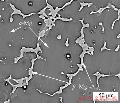
Fig. 1 SEM micrograph of as-received AZ91 alloy
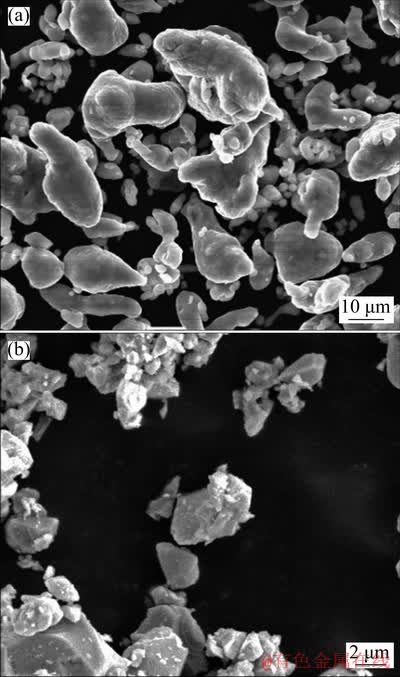
Fig. 2 SEM images of Al (a) and TiC (b) powder
A paste was prepared by blending the Al and TiC powder mixture using 10% polyvinyl alcohol (PVA) as a binder. The paste of the powder mixture was then applied on the polished surface of the AZ91 alloy substrate to make a 1 mm-thick layer. Finally, the powder mixture coated substrate was dried in a muffle furnace for 1 h at 80 °C in Ar atmosphere, and thus a pre-deposited Al-TiC layer with thickness of about 0.9 mm was obtained.
The TIG surface alloying was carried out using a TIG welding setup consisting of a motion unit that controls the arc movement at a specific speed. In addition, to protect the molten zone from atmospheric oxygen, a continuous flow of high purity argon gas was blown into the molten pool during the scanning of the TIG arc with a flow rate of 18 L/min. A thick aluminium plate was considered as base for faster removal of the excessive heat from the AZ91D Mg alloy plate during the scanning of TIG arc in order to avoid any burning of the substrate material. The TIG arc was created by using direct current at straight polarity condition. To produce and stabilize the arc, Ar gas was supplied through the TIG nozzle with a flow rate of 25 L/min. Figure 3 depicts the experimental setup used for the present TIG alloying using Al-TiC pre-deposited layer on AZ91D magnesium alloy. A number of trial experiments were conducted by varying the processing current from 30 to 80 A to obtain the optimum TIG alloying condition for the present set of experiments. For all the experiments, scan speed was maintained at 2 mm/s.
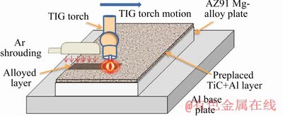
Fig. 3 TIG cladding experimental setup used to deposit Al-TiC composite coating on AZ91 alloy
During the TIG alloying process, it was evident that at currents of 30 and 40 A, due to inadequate heat, the metallurgical bond between the substrate and the coating was very weak and delamination of the coating from the substrate took place. It was also observed that at current above 70 A, the substrate started burning. Therefore, for subsequent analysis, only the samples processed at 50, 60 and 70 A were considered.
After formation of the composite layer, the cross-section of the individual track was sectioned using wire EDM for X-ray diffraction (XRD) analysis, scanning electron microscopy (SEM) and micro-hardness measurement. The standard metallography polishing of the cross-section was executed prior to hardness measurement and SEM analysis. The microstructural observation of the Al-TiC layer was performed using SEM operated in back scattered electron (BSE) mode. The distribution of the elements was analysed through energy dispersive spectroscopy (EDS). The phases present in the layer were recognized from the XRD patterns (Model: Rigaku Smart Lab X-ray diffractometer) operated with cobalt target. The micro-hardness values were measured along the depth of the coating at an interval of 50 μm using a Vickers micro-hardness tester (Model: Leco LM810).
The sliding wear test of a selective coated sample (70 A) was performed in dry condition against hardened steel disc with hardness value of HRC 58. Prior to wear test, the pin of 4 mm in diameter was extracted from the clad track with the help of wire EDM. The sliding wear test was executed by sliding the coated pin against the counter-plate under 5 N load and 260 mm/s sliding velocity using a pin-on-disc setup as per ASTM G99 standard. The height reduction considered as wear and the coefficient of friction (COF) of the coated pin as well as uncoated AZ91D magnesium alloy pin with respect to the test time were recorded through a data acquisition system.
3 Results and discussion
3.1 Coating morphology
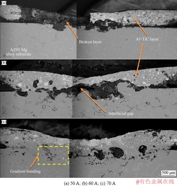
Fig. 4 SEM images of cross-section of Al-TiC coating produced on AZ91 alloy at different processing currents
Figure 4 illustrates the SEM images of the cross-section of Al-TiC coating produced by TIG arc scanning on AZ91 alloy at the processing currents of 50, 60 and 70 A. It is evident that for all the processing current, a thick layer of coating forms on the substrate surface. However, a significant variation in the morphology of the coating and the structure of the interfacial zone can be observed. At low processing current (50 A), as the induced heat through TIG arc is relatively less, the TiC+Al coating layer is not blended properly with the substrate, and a distinct interfacial gap can be seen between the coating and the substrate (Fig. 4(a)). Additionally, the TiC particles are not melted and blended with the Al matrix owing to inadequate heat, and consequently non-uniformity in the coating morphology occurs. It is also evident that the coating layer is partially fragmented and detached from the substrate, which perhaps occurs during the sample preparation as a consequence of the weak bond between the substrate and the coating. At a processing current of 60 A, the coating layer is partially blended with the substrate and relatively thicker layer forms. It is also seen that in this sample (Fig. 4(b)), the interface of the coating is partially removed from the middle portion of the track due to inadequate bonding or formation of the void during TIG arc scanning. In contrast, by employing current of 70 A, the coating layer is mixed with the substrate more uniformly and a thick layer forms, as shown in Fig. 4(c). Careful observation of the image reveals that the amount of the white shaded TiC particles is large at the top surface and reduces gradually towards the interface.
The thickness of the coating was measured at different locations of the track and the average coating thickness was calculated for the three different specimens and plotted in Fig. 5. The graph shows that the average coating thickness is increased from 610 to 760 μm with increasing the processing current from 50 to 70 A. Although the initial preplaced powder layer thickness is approximately 900 μm for all the specimens, it is expected that during the TIG arc scanning, part of the preplaced powder is evaporated and the coating layer thickness is reduced substantially. Furthermore, it is also possible that, during the preplacement of the powder mixture, a loosely bonded layer forms, and in the course of arc scanning the powder mixture layer becomes compacted and the overall thickness of the coating is reduced through melting and solidification cycle. Nevertheless, as discussed earlier, at relatively high processing current, the substrate surface is partially melted and blended with the coating material, which consequently enhances the coating thickness.
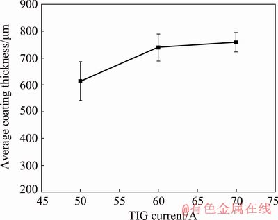
Fig. 5 Average coating thickness measured at cross section of Al-TiC coating produced on AZ91 alloy at different welding currents
Thus, with increasing the processing current, overall coating thickness is increased gradually through dilution of the coating material with the molten substrate.
Since the alloyed layer produced at the current of 70 A shows adequate uniformity in the thickness and morphology in combination with sufficient bonding with the substrate, an in-depth microstructural analysis was carried out for the said sample. Figure 6 shows the SEM images of the centre region of the clad layer (corresponding to selected region of Fig. 4(c)), and corresponding highly-magnified image. Figure 6(a) shows an almost uniform distribution of white shaded particle-like structure within the grey shaded matrix. Nevertheless, some agglomerated particles are also visible in the coating layer. The magnified image of this region shown in Fig. 6(b) exhibits that the size of these particle-like structures is in the range of 1-10 μm. The EDS elemental mapping corresponding to the image as illustrated in Fig. 7 indicates that the white shaded particles are rich in Ti and C as major elements, and the grey shaded region is composed of Al, Mg and O. Thus, it is concluded that the white shaded TiC particles are embedded within the matrix consisting of a solid solution of Al and AZ91 alloy. During TIG arc scanning over the layer of Al-TiC powder mixture, the intense heat of the arc melts the Al powder along with the surface of the alloy substrate. The TiC powder, on the other hand, owing to its high melting temperature, is melted partially or fragmented by cracking due to the development of thermal stress. These fragmented or partially-melted TiC particles are embedded in the matrix and create a metal matrix-like structure in the coating layer.
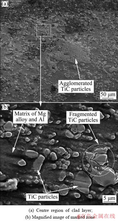
Fig. 6 SEM images of Al-TiC coating on AZ91 alloy at processing current of 70 A (corresponding to selected regions of Fig. 4(c))
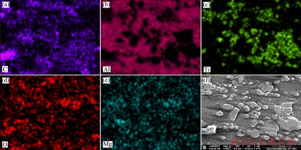
Fig. 7 EDS elemental mappings of centre zone of Al-TiC coating produced on AZ91 Mg alloy by TIG cladding method at current of 70 A (corresponding to Fig. 6(b))
The SEM image of the interface region for the Al-TiC coating layer on AZ91 alloy substrate produced at current of 70 A, as depicted in Fig. 8, shows that no interfacial gap forms between the clad layer and the substrate. A gradient microstructure, with a lower fraction of TiC particles at the bottom side of the clad layer, can be seen, which indicates the formation of a strong interface between the Al-TiC composite layer and the substrate.
3.2 XRD analysis
Figure 9 illustrates the XRD spectra taken from the as-received AZ91 alloy substrate and the Al-TiC coating deposited on it by TIG cladding route at current of 70 A. The XRD pattern of the AZ91 alloy shows the presence of primary Mg (α-Mg) and Mg17Al12 phases. On the contrary, the pattern from the Al-TiC coating exhibits the presence of Al, TiC, and Al4C3 phases along with primary Mg and Mg17Al12 phases. No peak of MgO is detected from the spectra taken from the coating surface, indicating that the oxidation of the AZ91 alloy substrate is prevented during the TIG arc scanning due to the presence of Al-TiC coating and application of Ar gas shrouding to create the inert atmosphere. The formation of Al4C3 phase in the coating layer may be accredited to the partial dissociation of the TiC at high temperature and subsequent reaction with the molten Al.
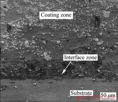
Fig. 8 SEM image of Al-TiC coating and AZ91 alloy interface for clad layer produced at processing current of 70 A
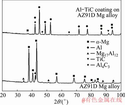
Fig. 9 XRD patterns of Al-TiC coated (processing current of 70 A) and uncoated AZ91 alloy
3.3 Micro-hardness
The micro-hardness values measured along the depth of the clad layer are plotted against the depth in Fig. 10. The plot reveals that the hardness values for all the clad layers produced at different processing currents are reasonably higher than the value of the substrate region. It is evident that the micro-hardness value at the coating region is fluctuating between 160 HV0.25 and 305 HV0.25 with the variation of processing current and depth of the coating. The hardness value at the substrate region is recorded in the range of 45-60 HV0.25.
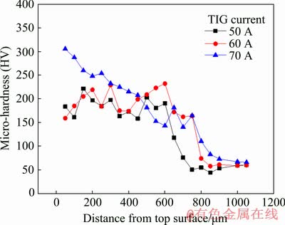
Fig. 10 Variation of microhardness value from top of Al-TiC composite coating towards AZ91 alloy substrate deposited by TIG cladding method at different processing currents
It is also evident that for the specimens prepared at processing currents of 50 and 60 A, the hardness value randomly changes within the clad layer and then is suddenly reduced at the substrate region. However, for the clad layer produced at current of 70 A, the hardness value is reduced gradually towards the coating substrate interface and becomes steady at the substrate region. A careful observation of the plot reveals that the clad layer hardness is reduced to the hardness value of the substrate after a depth of approximately 700 μm, which is almost equivalent to the coating thickness obtained through the SEM images of the coating cross-section.
The improved micro-hardness in the clad layer is obtained predominantly due to the presence of TiC particles embedded within the Al-Mg alloy matrix of the clad layer. The hardness value fluctuates along the depth of the clad layer because of non-uniform distribution of the TiC particles in the matrix, which can be evident from the macrostructure of the clad layer produced at processing currents of 50 and 60 A. However, it is seen that the amount of TiC particles is reduced gradually with the depth of the clad layer and consequently the hardness value diminishes steadily.
3.4 Dry sliding wear behaviour
To comprehend the improvement in the wear resistance of the Al-TiC coating deposited on AZ91 Mg alloy, the wear values of the coated specimen produced with current of 70 A, and the as-received substrate alloy were measured by performing pin-on-disc type sliding wear test against a harden die steel (HRC 58). The cumulative wear (against time) and the coefficient of friction (COF) were acquired from the data acquisition system in terms of the height loss of the pin specimens. Figure 11(a) shows the variation of wear in terms of height loss against the sliding time for the uncoated and Al-TiC coated AZ91 alloy. The uncoated alloy exhibits a final height loss of 80 μm, whereas the coated sample shows a final height loss of 25 μm at the end of 3 min of test. Careful analysis of the plot shows that for the coated sample, at the initiation of the test, a large variatiion in the height loss occurs, and after a certain preiod, the height loss becomes steady with almost negligible wear rate.
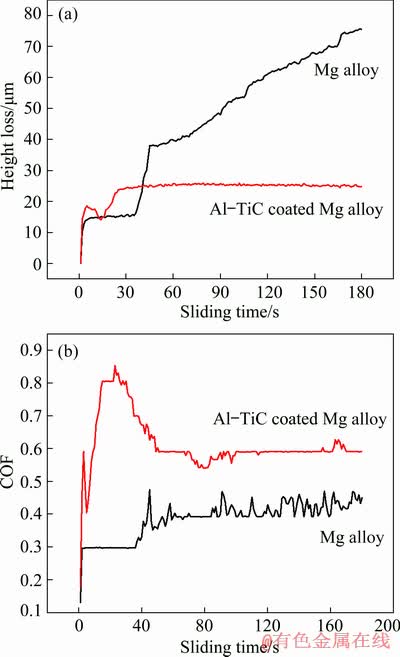
Fig. 11 Variation of wear (height loss of pin) (a) and COF (b) against sliding time for Al-TiC coated and uncoated AZ91 Mg alloy
Due to low hardness of the AZ91 alloy, its wear against hardened steel is significant, and with the test time the height loss of the pin specimen increases cumulatively and exhibits high wear value. On the other side, owing to the presence of hard TiC paritcles, the coated surface exhibits high resistance to the sliding wear, which predominantly occurs due to plastic defromation of the material against a harder counter-part. Here, the hardness of TiC is resonably high as compared to the hardened steel. Althouh the hardness value of the produced Al-TiC composite is lower than that of the counter body, the presence of extreemly hard TiC particles restrains the deformation and exhibits almost negligible removal of the coating material under the present test condition. Due to a certain level of irregularity in the coating surface, at the initiation of the test, the undulation from the coated surface and the fluctuation in the wear value are observed.
From the coefficient of friction (COF) plot as illustrated in Fig. 11(b), it is evident that the steady state COF value for uncoated AZ91 Mg alloy is approximately 0.4, whereas the steady state COF for Al-TiC coated AZ91 Mg alloy is 0.6. The higher COF in the coated surface perhaps is obtained due to the presence of TiC particles. From the plot, it may be also noticed that at the initiation of the test the COF value for the coating is reasonably higher (up to 0.8), and the value is reduced to 0.6 after a certain time. It is possible that due to the undulation in the coating surface, at the initiation of the test, the frictional force is higher, and accordingly a higher COF value is obtained. On the contrary, for uncoated pin, at the commencement of the test, the pin surface is smooth (as-received polished surface), and exhibits low COF (0.3); with the test time, due to oxidation nature of the Mg alloy, some oxide layer forms on the substrate surface and enhances the COF value.
In addition, to evaluate the performance of the produced Al-TiC alloy coating deposited on AZ91 Mg alloy, the wear test was also performed for a longer time period (30 min) and the result was compared with the earlier test results (obtained for 3 min), as illustrated in Fig. 12. From the plot, it is clearly evident that even after 30 min of test, the wear value of the coating is almost negligible as compared to the uncoated substrate. The test results indicate that the Al-TiC coating is a potential candidate to improve the surface properties of AZ91 Mg alloy and TIG cladding can be considered as a suitable and economical approach in this regard.
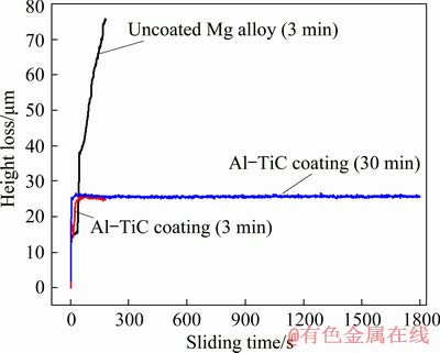
Fig. 12 Comparison of wear performance of Al-TiC coated AZ91 Mg alloy for longer test time against that of substrate
The SEM images of the worn surfaces of uncoated AZ91 magnesium alloy (after 3 min of test), and Al-TiC coated Mg alloy (after 3 and 30 min of test) are shown in Fig. 13. The images show that for uncoated AZ91 magnesium alloy, large size grooves or scratches appear on the worn surface. On the contrary, for the Al-TiC coated specimen (after 3 min of wear test), the coating material remains on the surface and minor scratches form. Conversely, for the coated specimen after 30 min of test, it is seen that some deformation in the coating surface occurs. Additionally, some minor cracks and cavities are also found on the worn surface. However, no major scratches are detected on the coating surface after the wear test.
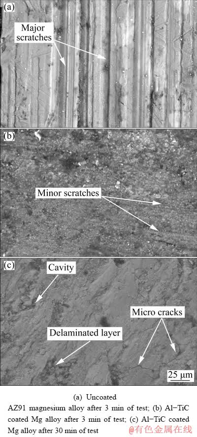
Fig. 13 SEM images of worn surfaces
As a soft material, when AZ91 magnesium alloy undergoes wear test, major scratches form on the contact surface. On the other hand, due to high hardness of the Al-TiC composite coating yielded on the AZ91 magnesium alloy, during the wear test, the coating layer resists to form any scratch or plastic deformation for a shorter duration of test. However, owing to continuous sliding of the coated specimen against the hard steel plate for a longer time of test, the coating material becomes plastically deformed and some micro-cracks form. In addition, some cavities are also yielded on the worn surface due to the delamination of the plastically deformed layer.
4 Conclusions
(1) The Al-TiC coating was deposited on AZ91 Mg alloy substrate by TIG alloying method using a precursor mixture of TiC and Al powder with suitable processing condition.
(2) The microstructural analysis shows that the coating morphology largely depends on the processing current. The formation of the interfacial gap or pores becomes predominate under inappropriate processing condition.
(3) The deposited alloy layer unveils substantially high hardness (up to 305 HV0.25) as compared to the AZ91 Mg alloy substrate (60 HV0.25). The variation of hardness value in the alloy layer is partially governed by the processing current, which influences the dilution of the alloy layer.
(4) The sliding wear test performed against harden steel disc (HRC 58) shows that the wear values of the coatings as compared to the uncoated AZ91 Mg alloy is almost negligible, even for a longer period of test.
(5) The coefficient of friction of the produced Al-TiC alloy layer is found approximately to be 0.6, which is higher than that of the uncoated AZ91 Mg alloy (0.4) under similar test condition.
References
[1] MORDIKE B L, EBERT T. Magnesium: Properties- applications-potential [J]. Materials Science and Engineering A, 2001, 302: 37-45.
[2] LIU J L, YU H J, CHEN C Z, WENG F, DAI J J. Research and development status of laser cladding on magnesium alloys: A review [J]. Optics and Lasers in Engineering, 2017, 93: 195-210.
[3] ELAHI M R, SOHI M H, SAFAEI A. Liquid phase surface alloying of AZ91D magnesium alloy with Al and Ni powders [J]. Applied Surface Science, 2012, 258: 5876-5880.
[4] ZHENG B J, CHEN X M, LIAN J S. Microstructure and wear property of laser cladding Al+SiC powders on AZ91D magnesium alloy [J]. Optics and Lasers in Engineering, 2010, 48: 526-532.
[5] REZAEE M, FARAHANI M, PAKRAVAN M, SHAHMIRZALO A. Corrosion resistance and hydrophilic properties of plasma sprayed Ni+5%Al coatings [J]. Heliyon, 2019, 5: e01920.
[6] WANG Y, WEI D, YU J, DI S. Effects of Al2O3 nano- additive on performance of micro-arc oxidation coatings formed on AZ91D Mg alloy [J]. Journal of Materials Science and Technology, 2014, 30: 984-990.
[7] MONDAL A K, KUMAR S, BLAWERT C, DAHOTRE N B. Effect of laser surface treatment on corrosion and wear resistance of ACM720 Mg alloy [J]. Surface and Coatings Technology, 2008, 202: 3187-3198.
[8] CARCEL B, SAMPEDRO J, RUESCAS A, TONEU X. Corrosion and wear resistance improvement of magnesium alloys by laser cladding with Al-Si [J]. Physics Procedia, 2011, 12: 353-363.
[9] HAZRA M, MONDAL A K, KUMAR S, BLAWERT C, DAHOTRE N B. Laser surface cladding of MRI 153M magnesium alloy with (Al+Al2O3) [J]. Surface and Coatings Technology, 2009, 203: 2292-2299.
[10] TAN C, ZHU H, KUANG T, SHI J, LIU H, LIU Z. Laser cladding Al-based amorphous-nanocrystalline composite coatings on AZ80 magnesium alloy under water cooling condition [J]. Journal of Alloys and Compounds, 2017, 690: 108-115.
[11] LIN P Y, ZHANG Z H, REN L Q. The mechanical properties and microstructures of AZ91D magnesium alloy processed by selective laser cladding with Al powder [J]. Optics and Laser Technology, 2014, 60: 61-68.
[12] YANG Y, WU H. Improving the wear resistance of AZ91D magnesium alloys by laser cladding with Al-Si powders [J]. Materials Letter, 2009, 63: 19-21.
[13] LEI Y W, SUN R L, TANG Y, NIU W. Experimental and thermodynamic investigations into the microstructure of laser clad Al-Si coatings on AZ91D alloys [J]. Surface and Coatings Technology, 2012, 207: 400-405.
[14] LIU Y H, GUO Z X, YANG Y, WANG H Y, HU J D, LI Y X, CHUMAKOV A N, BOSAK N A. Laser (a pulsed Nd:YAG) cladding of AZ91D magnesium alloy with Al and Al2O3 powders [J]. Applied Surface Science, 2006, 253: 1722-1728.
[15] QIAN J G, ZHANG J X, LI S Q, WANG C. Study on laser cladding NiAl/Al2O3 coating on magnesium alloy [J]. Rare Metal Materials and Engineering, 2013, 42: 466-469.
[16] MRIDHA S, BAKER T N. Overlapping tracks processed by TIG melting TiC preplaced powder on low alloy steel surfaces [J]. Materials Science and Technology, 2015, 31: 337-343.
[17] SAHOO C K, MASANTA M. Microstructure and wear characteristic of hard and wear resistance TiC coating deposited on aluminium by tungsten inert gas (TIG) cladding process [J]. Journal of the Brazilian Society of Mechanical Sciences and Engineering, 2018, 40: 247.
[18] SAROJ S, SAHOO C K, MASANTA M. Microstructure and mechanical performance of TiC-Inconel825 composite coating deposited on AISI 304 steel by TIG cladding process [J]. Journal of Materials Processing Technology, 2017, 249: 490-501.
[19] DU B, WANG X, ZOU Z. Microstructure and tribological behavior of laser in situ synthesized TiC-reinforced Fe-based composite coatings [J]. Tribology Letters, 2011, 43: 295-301.
[20] USHASHRI K, MASANTA M. Hard TiC coating on AISI304 steel by laser surface engineering using pulsed Nd:YAG laser [J]. Materials and Manufacturing Processes, 2015, 30: 730-735.
[21] SAHOO C K, SONI L, MASANTA M. Evaluation of microstructure and mechanical properties of TiC/TiC-steel composite coating produced by gas tungsten arc (GTA) coating process [J]. Surface and Coatings Technology, 2016, 307: 17-27.
Chinmaya Kumar PADHEE1, Manoj MASANTA1, A. K. MONDAL2
1. Department of Mechanical Engineering, National Institute of Technology Rourkela, Rourkela 769008, India;
2. Department of Metallurgical Engineering, Indian Institute of Technology (BHU) Varanasi, Varanasi 221005, India
摘 要:尝试以TIG电弧为热源,通过Al和TiC的混合物进行表面合金化以改善AZ91镁合金的表面性能。通过扫描电镜(SEM)和X射线衍射(XRD)分析AZ91合金层的显微组织演化。采用维氏显微硬度计和销-盘磨损试验分别研究显微硬度和干滑动磨损行为。结果表明,在一定的电流和扫描速度下,AZ91合金基体上形成近均匀的合金层。合金层的硬度值达305 HV0.25,与AZ91合金基体相比,合金层的磨损几乎可以忽略不计。
关键词:AZ91镁合金;Al-TiC涂层;TIG合金化;显微硬度;干滑动磨损
(Edited by Bing YANG)
Corresponding author: Manoj MASANTA; Tel: +91-661-2462530; Fax: +91-661-2462501; E-mail: manoj.masanta@gmail.com,
masantam@nitrkl.ac.in
DOI: 10.1016/S1003-6326(20)65318-3

