Elastoplastic model for discontinuous shear deformation ofdeep rock mass
来源期刊:中南大学学报(英文版)2011年第3期
论文作者:王明洋 范鹏贤 钱七虎 邓宏见
文章页码:866 - 873
Key words:deep rock mass; discontinuous deformation; elasto-plastic model
Abstract: Deep rock mass possesses some unusual properties due to high earth stress, which further result in new problems that have not been well understood and explained up to date. In order to investigate the deformation mechanism, the complete deformation process of deep rock mass, with a great emphasis on local shear deformation stage, was analyzed in detail. The quasi continuous shear deformation of the deep rock mass is described by a combination of smooth functions: the averaged distribution of the original deformation field, and the local discontinuities along the slip lines. Hence, an elasto-plastic model is established for the shear deformation process, in which the rotational displacement is taken into account as well as the translational component. Numerical analysis method was developed for case study. Deformation process of a tunnel under high earth stress was investigated for verification.
J. Cent. South Univ. Technol. (2011) 18: 866-873
DOI: 10.1007/s11771-011-0775-6![]()
WANG Ming-yang(王明洋)1, FAN Peng-xian(范鹏贤)1, QIAN Qi-hu(钱七虎)1, DENG Hong-jian(邓宏见)2
1. Engineering Institute of Engineering Corps, PLA University of Science and Technology,
Nanjing 210007, China;
2. Institute of Structural Mechanics, China Academy of Engineering Physics, Mianyang 621900, China
? Central South University Press and Springer-Verlag Berlin Heidelberg 2011
Abstract: Deep rock mass possesses some unusual properties due to high earth stress, which further result in new problems that have not been well understood and explained up to date. In order to investigate the deformation mechanism, the complete deformation process of deep rock mass, with a great emphasis on local shear deformation stage, was analyzed in detail. The quasi continuous shear deformation of the deep rock mass is described by a combination of smooth functions: the averaged distribution of the original deformation field, and the local discontinuities along the slip lines. Hence, an elasto-plastic model is established for the shear deformation process, in which the rotational displacement is taken into account as well as the translational component. Numerical analysis method was developed for case study. Deformation process of a tunnel under high earth stress was investigated for verification.
Key words: deep rock mass; discontinuous deformation; elasto-plastic model
1 Introduction
Along with the increasing exploitation of underground space and resources, the frequent catastrophes in deep-seated rock engineering, such as large shear deformation, rock burst, roof spalling and mining-induced earthquake appear on the scene, and have interested the scholars and engineers. However, the understanding of these complex physical and mechanical behaviors of rocks still remains in the primary stage and cannot yet fully meet the needs of engineering design [1].
Previous research on deep rock mass was mainly focused on two areas: the first one is physical modeling under mining or laboratory conditions based on monitoring and observations [2-7], while the other is theoretical analysis [8-11], using the continuum mechanics, micromechanics, or damage mechanics, to study the relationship between the stability of rock mass and its physical and mechanical properties.
Experiments and observations indicate that the deformation of rock mass undergoes brittle-ductile transformation under high confining stress [5]. The mechanism of its plastic deformation is connected with the localization of shear along certain surfaces, along which the tangential deformation vectors experience a violent break. The classical descriptions of large shear deformation of solid materials are generally based on the assumption of sufficient smoothness of the deformation field, and thus not sophisticated enough to characterize the discontinuous deformation field. Therefore, a discontinuous and nonlinear mathematical method is needed to analyze the problems that relate to large shear deformation. In the past decades, several attempts were made to develop a discontinuous description of the localized shear deformation of deep rock mass and other solid materials [12-14]. However, the mathematical difficulty makes the establishment of a practical procedure very hard to implement.
In this study, the shear deformation process of deep rock mass is focused on and a mathematical description of discontinuous local shear deformation field is proposed, based on which an elasto-plastic model is established. A finite element method analysis programme is developed. And one case study is done to follow up the model.
2 Mathematical description
2.1 Description of discontinuous deformation field
When the rocklike materials undergo large shear deformation, the tangential deformation along the interfaces is discontinuous. However, with several constraints, such discontinuities can be described by a combination of two smooth functions, one of which represents the averaged distribution of the original displacement field, and the other describes the local discontinuities. Herein, the lines along which the deformation vector is discontinuous are called slip lines, and the jump value of the deformation discontinuities between the two sides of slip line is called local shear deformation.
In the plane problems, define areas in which deformation field is smooth and continuous as elements. Thus, the boundaries of elements are slip lines. Along the slip lines, the deformation field is discontinuous, while the first derivative of deformation is continuous.
Consider a vector variable ![]() and its corresponding vector function
and its corresponding vector function ![]() (e1, e2 are standardized orthogonal basis). Assume that the function of original deformation field
(e1, e2 are standardized orthogonal basis). Assume that the function of original deformation field ![]() is averaged and smoothed as
is averaged and smoothed as ![]() with
with ![]() at the center of element
at the center of element ![]() Herein, the values of derivative
Herein, the values of derivative ![]() on both sides of the discontinuity are assumed to be the same.
on both sides of the discontinuity are assumed to be the same.
Form a two order tensor A with smooth components.
![]() k, m=1, 2 (1)
k, m=1, 2 (1)
On the boundary of two adjacent elements (with their centers at ri and ri+1), the value of discontinuity approximately equals A(ri)(ri+1-ri).
Thus, the original deformation field can be described by a combination of a corresponding smooth vector field u(r) and a tensor field A(r).
Supposing that the density of medium remains unchanged under shear and the component of original deformation field that is normal to the boundary of element is continuous, the four components of tensor A can be determined by two invariables Γ (major shear strain) and Ω:

The value of variable Ω can be expressed by the following equation:
![]() (2)
(2)
The variable Ω describes the difference of curls between the original and averaged deformation field.
For describing the net of slip lines (one set of slip lines is normal to the other set), an orthogonal curvilinear coordinate system (λ1, λ2) is employed, as shown in Fig.1.
![]() (3)
(3)
where x1, x2 are the Cartesian coordinates. As shown in Fig.1, θ is the angle between the direction of the major principal stress and axis Ox1, and the tangent of λ1 inclines at angle θ-π/4 to the axis Ox1.
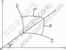
Fig.1 Cartesian and curvilinear coordinate
Assume that under certain conditions the deformed area enters the plastic zone completely, and the plasticity condition bears no relation to the first invariant stress tensor.
Let ![]() ,
, ![]() , where a1, a2 are the
, where a1, a2 are the
Lame constants relating to the transformation between the orthogonal curvilinear and Cartesian coordinates, and l1, l2 are the lengths of arcs along the corresponding curves.
Hence, we have
![]()
![]() (4)
(4)
Besides the direction of slip lines, the second parameter that describes the net of slip lines is the dimension of element. Herein, two sets of orthogonal curves are chosen, with constants λ1 and λ2 divided into segments, having dimensions of ![]()
![]()
![]() The whole plastic zone is thus discretized into elements. The boundary lengths of element at point (λ1, λ2) are
The whole plastic zone is thus discretized into elements. The boundary lengths of element at point (λ1, λ2) are ![]() and
and ![]()
![]() and
and ![]() are the distributing functions of slip lines.
are the distributing functions of slip lines.
Because the plasticity of the element relates to its dimension, it can be assumed that the stresses in the element also depend on the element’s dimension. In other words, the density of slip lines net is determined by the stress field. The problem how slip lines transit from an area with higher stress to an area with lower stress is not well studied yet. Herein, the deformation studied is after slip lines net has formed, and the functions ![]() ,
,![]() that describe the density of slip lines are assumed to be predefined.
that describe the density of slip lines are assumed to be predefined.
2.2 Shear deformation along slip lines
Although the total displacement consists of deformation along the slip lines and deformation within the elements, discontinuities occur only along the slip lines.
Define Un, un as the cast of the original deformation vector and the averaged deformation vector on the direction tangent to the slip line, respectively.
Therefore, the local shear deformation along one side of a slip line can be expressed as
![]()
![]()
![]() (5)
(5)
Similarly, the local shear deformation along the other side of the slip line is
![]()
![]()
![]() (6)
(6)
![]() only exist along the slip lines and describe the exact values of the shear deformation of elements along these lines. Apparently, the local deformation relates to the elements dimension.
only exist along the slip lines and describe the exact values of the shear deformation of elements along these lines. Apparently, the local deformation relates to the elements dimension.
The possible tangential stress of the slip lines can be determined by the corresponding local deformation:
![]() ,
, ![]()
Herein and afterward, the superscript “0” implies that the corresponding variable represents the parameter along the slip line.
2.3 Balance equation
The transferring and dissipating of energy are closely coupled with the emerging, displacing and developing of interfaces within the rock mass itself. And the discontinuous interfaces result in the discontinuity of deformation field and asymmetry of stress tensor. Hence, the local deformation resulted from the discontinuous interfaces has both the displacement of rotation as well as that of translation.
Because of the asymmetry of the stress tensor resulted from the slip lines, distributed moment must exist along the discontinuous lines to maintain the balance. Define F1, F2 as volume forces, and μ11, μ22 as moments of distribution. Based on the balance conditions of momentum and momentum moment, the balance equation in the cartesian coordinate system is derived:
 (7)
(7)
Forces between two adjacent elements transfer only through stress distributed on the boundary. Distributed moments μ11, μ22 are produced from the asymmetry of distributed stress. The stress on the boundaries of elements can be decomposed into the symmetrical component, and the antisymmetric component, responsible only for the force and the moment, respectively.
Assume W to be the elastic energy stored in area D within elasto-plastic medium in the orthogonal curvilinear coordinate system. W can be calculated by the expression as
![]() (8)
(8)
Assume that the energy satisfying the balance conditions and boundary conditions is the minimum of all the possibilities. When W reaches its minimum, there is a supplemented equation:
![]() (9)
(9)
The deformation process is a time-dependent process, but the deformation of the deep rock mass develops very slow actually. Hence, the rotational deformation can be regarded as an internal variable. In order to simplify the problem, the control balance equations of static state are adaptable.
2.4 Geometrical equations
Because the ultimate deformation of rock-like material is generally minute, we can assume that the gradient orientation of deformation velocity field is consistent with the orientation of the principal axial of the stress field. Thus, the description of large deformation is simplified. The relationship between the deformation field and the stress field can be established by the increment of velocity or that of deformation.
The deformation gradient of the averaged deformation field in the cartesian coordinate system and its increment can be expressed as
 ,
,  (10)
(10)
The tensor of the deformation grads F0 in the orthogonal curvilinear coordinate system can be calculated by

 (11)
(11)
For simplification, Eq.(11) is rewritten as
![]() (12)
(12)
where
![]()
![]()
The matrix R is the transform matrix from the cartesian coordinate system to the orthogonal curvilinear coordinate system:

Similarly, there is ΔF0=RΔF as well.
3 Elasto-plastic model of local shear deformation stage
The deformation process of the deep rock mass can be divided into three stages. The first stage is the elastic stage, in which the relationship between the strain and the stress is linear. The second stage is the quasi plastic stage. In this stage, the plastic deformation is still minute as well as local shear deformation, and ignoring the dissymmetrical stress is acceptable. The third stage, the local shear deformation stage, is the most complex stage. Because there are plenty of literatures devoted to the first two stages, only the third stage is investigated here in detail.
3.1 Stress-strain relationship along slip lines
The deformation of elements is recoverable, while the local deformation along the slip lines is not recoverable. Because the deformation vectors are orthogonal with the element boundaries, the compression deformations of the original discontinuous deformation field and the averaged smooth deformation field are consistent with each other.
Generally, shear stresses ![]() are not equal to each other. They are the combinations of stress system
are not equal to each other. They are the combinations of stress system ![]() and
and ![]() :
:![]() ,
,![]() . According to the law of symmetry, the elastic shear deformation exists only when
. According to the law of symmetry, the elastic shear deformation exists only when ![]()
Let G be the shear modulus. The value of elastic deformation is
![]() (13)
(13)
Substituting Eq.(13) into Eq.(5) and Eq.(6), the following equations are obtained:
![]()
![]() (14)
(14)
![]()
![]() (15)
(15)
For the plane stress problems with elastic deformation within elements, the stress-strain relationship of slip lines in the local coordinate system can be depicted by equations set (16). In the following equations, μ is Poisson ratio, and T(r12), T(r21) are the stress-deformation functions along slip lines.
 (16)
(16)
The first two equations of equations set (16) describe the elastic deformations of elements, and the latter two characterize the local shear deformations along the slip lines.
Referring to the geometric equations, constitutive equations along the slip lines in the local curvilinear coordinate system can be rewritten as
 (17)
(17)
The increment format of constitutive equations can also be written in a similar form:
 (18)
(18)
3.2 Dimension factor of shear deformation element
The dimension factor of shear slip elements is related to the distribution of stress. Assuming the function of dimension to be constant, it can be determined alone by the Lame constants of the local orthogonal coordinate system. At the same time, the orientation of the local shear slip can be determined by the stress state combined with the strength criterion.
In the local shear slip field, the coordinates of the local orthogonal coordinate system can be calculated by coordinates in the cartesian coordinate system through the following equation:
 (19)
(19)
The Lame constants of the local orthogonal coordinate system can be calculated by the following expression:


3.3 Rotational component of deformation field
The rotational deformation field is needed in the computation of stress-deformation relationship. It can be determined by two methods. One is by determining the function conditions through which the slip lines interact with each other. This method needs actual tests to provide material parameters. The other method is through determining the evolution function of the rotational deformation field by the least-energy principle. The latter method is adopted here.
The energy dissipation along the slip lines can be expressed as
![]()
![]()
![]() (20)
(20)
where |J| is the Jacobian determinant of the energy function.
The shear force along the slip lines must satisfy equations set (16).
Applying Lagrange bound variational method to the above equation, it is deduced:

![]()

 (21)
(21)
Applying the variational approach again to Eq.(21), we obtain
![]()
![]()
![]()
![]()
Combining the above four equations, the evolution equation of the rotational deformation field is obtained:
![]()
![]()
![]() (22)
(22)
From Eq.(17), we have
![]() (23)
(23)
![]() (24)
(24)
Combining Eqs.(22), (23) and (24) together, equations set (25) are derived:
 (25)
(25)
Equations set (25) is based on the least-energy principle, and characterizes the rotational component of stress-deformation relation along the slip lines.
4 Numerical analysis
4.1 Numerical analysis program and studied cases
Existing numerical methods generally do not take the dissymmetry of stress tensor and the rotational deformation into account [15]. Hence, a new program for plane problems is developed to simulate the local shear deformation process.
The program engaged here comprises three main parts: the fore treatment processor, the main program, and the post processor. Data of the discrete model are provided by the fore treatment processor. Based on the discrete model, the main programme executes numerical calculation. At last, the post processor produces the analysis results and makes them visible.
Based on the proposed model, a problem about excavating in rock under high earth stress, which can be approximately regarded as plane strain problems, is studied.
A circular tunnel with a diameter of 5 m was excavated in a 100 m × 100 m rectangular area (refer to Fig.2). The compressive stress on the boundary of the tunnel was released linearly in 10 ms. Three cases were designed to explore the influence of parameters (including unloading modulus, tensile strength and earth stress) on the local shear deformation process of deep rock mass. The material parameters are listed in Table 1.
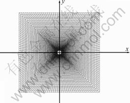
Fig.2 Sketch map of outline and discretization
Table 1 Material parameters of studied case

4.2 Results and discussion
In Case 1, the tensile stress emerged in the area near the inner boundary. With the increase of the distance from the boundary, the circumferential stress increased to 26 MPa, exceeding the earth stress, and then gradually returned to the earth stress. The maximum displacement toward the centre of the tunnel took place on the boundary and reached 7.2 mm in 12 ms. Local shear deformation zone appeared, in which tensile failure zone was developed. Their radii were 5.02 m and 2.59 m, respectively. The stress state of surrounding rock at the 12 ms is shown in Fig.3(a).
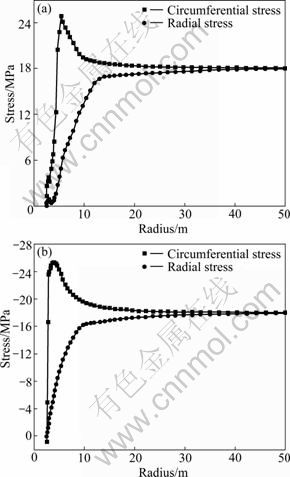
Fig.3 Curves of circumferential and radial stress at 12 ms: (a) Case 1; (b) Case 2
Case 2 shows a similar trend to case 1, as shown in Fig.3(b). But the local shear deformation zone, with 2.81 m in radius, was much smaller. And no tensile failure zone developed. The shrinking of the local shear deformation zone and absence of tensile failure zone indicated that the unloading modulus had a noteworthy influence on the local shear deformation. The local shear deformation zone increased with the unloading modulus.
In Case 3, the material with a larger earth stress and little tensile strength is considered to investigate the progressive failure process of surrounding rock.
When the stress was first released, the circumferential compressive stress concentrated on the boundary of the tunnel. Before the failure, the circumferential stress decreased, while the radial stress increased, along with the increase of the distance from the inner boundary, and eventually both of them approached the remote earth stress. But during the stress releasing, the shear deformation developed, the circumferential stress of the zone nearby the boundary decreased, and the peak moved diverges from the boundary. After the unloading process, the peak value of circumferential stress reached its maximum, about 80 MPa, or 1.6 times larger than the initial earth stress. After the peak value, the circumferential stress gradually decreased to the remote earth stress. The radial stress increased as the distance increased all times. The stress state of surrounding rock at the 15 ms is shown in Fig.4. Some of the time-dependent results are listed in Table 2.
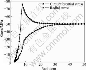
Fig.4 Curves of circumferential and radial stress of Case 3 at 15 ms
Table 2 Results of Case 3 versus time

The results of Case 3 showed that, with a larger earth stress and a little tensile strength, the surrounding rock had an acceleration trend of deforming, and developed a rather larger shear deformation zone and tensile failure zone.
Based on the results of the three studied cases, some preliminary insight into the deformation process of deep rock mass can be drawn.
As the stress of the boundary is gradually released, shear stress emerges and increases due to the variance among the principal stresses. And when the shear stress reaches and exceeds the critical strength, the surrounding rock turns into the post-peak deformation stage, in which the boundary conditions are met by the development of the local shear deformation and the slippage along the weak discontinuity. In the early stage of local shear deformation, the radial stress of the vicinity of inner boundary is very close to the elastic solution, while the circumferential stress is much less than the elastic solution. Both the radial stress and the circumferential stress of the region far from the inner boundary are approximately identical to the close-form analytical solution [16]. The stress of the vicinity of the inner boundary decreases after the failure of rock. However, in an annular region with certain radius, the circumferential stress exceeds the elastic stress solution, forming a so-called supporting compressive zone. In the supporting compressive zone, tensile stress appears, and if the tensile stress exceeds the tensile strength, new unloading surface will be formed.
From the articles devoted to relative problems, we can find some other collateral evidences to support the model proposed. For example, slip line net is found in the vicinity of tunnel boundary in-situ observation, and the zonal disintegration phenomena of deep-seated engineering. Because the tension fracture of compressed rock is very possible, the high stress in the supporting compressive zone might be a main reason for the zonal disintegration of deep rock mass. When the rock in that zone cracks, a new unloading surface will be formed. Then, a similar process repeats and another tensile cracking zone forms.
5 Conclusions
1) An elasto-plastic model of local shear deformation of deep rock mass is established. In the proposed model, the discontinuous deformation field is described by a combination of two smoothing functions, one of which represents the averaged deformation field, and the other describes the local discontinuities. The equations are derived based on equilibrium conditions, constitutive relationship, geometrical conditions and least-energy principle.
2) The deformation process of the surrounding rock of a circular tunnel under high earth stress is investigated by a newly developed program to verify the model. The elasto-plastic model coincides with the present understanding of deep rock mass.
3) Some factors influencing the deformation and failure properties are not taken into consideration here, so as to simplify the problem. Further theoretical and experimental investigations are therefore required to investigate the influence of high temperature, the transferring of energy, the scale effect of failure and so on.
References
[1] HE Man-chao. Present state and perspective of rock mechanics in deep mining engineering [C]// Chinese Society of Rock Mechanics and Engineering. Proceedings of the 8th Rock Mechanics and Engineering Conference. Beijing: Science Press, 2004: 88-94. (in Chinese)
[2] KURLENYA M V, OPARIN V N. Problems of nonlinear geomechanics: Part Ⅱ [J]. Journal of Mining Science, 2000, 39(4): 305-326.
[3] HE Man-chao, XIE He-ping, PENG Su-ping, JIANG Yao-dong. Study on rock mechanics in deep mining engineering [J]. Chinese Journal of Rock Mechanics and Engineering, 2005, 24(16): 2803-2813. (in Chinese)
[4] WANG Ming-yang, SONG Hua, ZHENG Da-liang, CHEN Shi-lin. On mechanism of zonal disintergration within rock mass around deep tunnel and definition of “deep rock engineering” [J]. Chinese Journal of Rock Mechanics and Engineering, 2006, 25(9): 1171-1176. (in Chinese).
[5] FAIRHURST C. Experimental physics and rock mechanics: Results of laboratory study [M]. Tokyo: A A BALKEMA, 2001.
[6] EBERHARDT E. Brittle rock fracture and progressive damage in uniaxial compression [D]. Saskatoon: University of Saskatchewan, 1998.
[7] PATERSON M S, WONG Teng-fong. Experimental rock deformation―The brittle field [M]. Berlin: Springer-Verlag, 2005: 59-143.
[8] KURLENYA M V, MIREKOV V E, KHAN G N. Stress-strain state in the vicinity of an extended working [J]. Soviet Mining Science, 1985, 20(4): 245-251.
[9] XIE He-ping, GAO Feng. The mechanics of cracks and a statistical strength theory for rocks [J]. International Journal of Rock Mechanics and Mining Science, 2000, 37(3): 477-488.
[10] CHEN Shi-lin, QIAN Qi-hu, WANG Ming-yang. Problems of deformation and bearing capacity of rock mass around deep buried tunnels [J]. Chinese Journal of Rock Mechanics and Engineering, 2005, 24(13): 2203-2211. (in Chinese)
[11] SHARAN S K. Analytical solutions for stresses and displacements around a circular opening in generalized Hoek-Brown rock [J]. International Journal of Rock Mechanics and Mining Science, 2008; 45(1): 78-85.
[12] REVUZHENKO A F, Shemyakin E I. Problem of plane strain of hardening and softening plastic materials [J]. Journal of Applied Mechanics and Technical Physics, 1977, 18(3): 406-420.
[13] WANG Ming-yang, ZHOU Ze-ping, QIAN Qi-hu. Tectonic, deformation and failure problems of deep rock mass [J]. Chinese Journal of Rock Mechanics and Engineering, 2006, 25(3): 448-455. (in Chinese)
[14] DENG Hong-jian. The elastic-plastic model for the local shear deformation of rock and the numerical analysis method [D]. Nanjing: PLA University of Science and Technology, 2007. (in Chinese)
[15] JING L. A review of techniques, advances and outstanding issues in numerical modelling for rock mechanics and rock engineering [J]. International Journal of Rock Mechanics and Mining Science, 2003, 40(2): 283-353.
[16] PENG Su-ping, ZHANG Jin-cai. Engineering geology for underground rocks [M]. Berlin: Springer-Verlag, 2007: 295-314.
(Edited by PENG Chao-qun)
Foundation item: Project(50825403) supported by the National Science Fund for Distinguished Young Scholars; Project(2010CB732003) supported by the National Key Basic Research Program of China; Project(51021001) supported by the Science Fund for Creative Research Group of the National Natural Science Foundation of China
Received date: 2010-03-16; Accepted date: 2010-06-01
Corresponding author: FAN Peng-xian, PhD candidate; Tel: +86-25-80822033; E-mail: fan-px@hotmail.com

