
Oxidation behavior of Ni(Co)CrAlYHf(Si) coatings on DS superalloy at 1 150 ℃
Huang Zhao-hui(黄朝晖), Tan Yong-ning(谭永宁), Zhao Xi-hong(赵希宏),
LI Jian-ping (李建平), ZHANG Qiang(张 强)
National Defence Key Laboratory for Advanced High Temperature Structural Materials,
Beijing Institute of Aeronautical Materials, Beijing 100095, China
Received 20 April 2006; accepted 30 June 2006
Abstract: Two Ni(Co)CrAlY coatings were deposited by EB-PVD method on a DS superalloy of Ni-Al-Cr-Co-W-Mo-Ta-Hf system. SEM, XEDS and XRD were used to study the oxidation behavior of the coatings. The two coatings show a good protection for the DS superalloy. The results of the isothermal oxidation test at 1 150 ℃ for 100 h show that the oxidation tendency obeys the parabolic law, and the oxidation rate constant Kp of the coated specimens decreases to about 1/3 of that for the bare superalloy. After oxidation, a continuous alumina-based scale is formed at the surfaces of the coated samples. Y2O3, NiO and SiO2 are also detectable in the oxide scale. A large number of Al in the coating is consumed due to high-temperature diffusion and oxidation reactions, and the NiAl phases in the coating are almost completely transformed to Ni3Al phases. For the Hf-bearing coating, some HfO2 particles exist at the interface between the coating and the substrate. Although internal oxidation occurs, the coating still shows a good adhesion with the superalloy substrate even after oxidation for 100 h. For the bare DS superalloy, after 100 h oxidation at 1 150 ℃, only discontinuous alumina-based oxide particles exist on the surface. Oxide spallation occurs for the bare alloy.
Key words: Ni(Co)CrAlY coating; DS superalloy; interdiffusion; oxidation behavior
1 Introduction
Advanced gas turbine engines operate with very high combustor exit temperatures to achieve the maximum engine performance and efficiency. The development of single crystal superalloy over the past 20 years has allowed the turbine inlet temperatures of aircraft engines to increase significantly. It is not likely that the temperature capability of superalloys will increase much further, but the requirement for high turbine operating temperatures is not diminished. Therefore, the life and service temperature of modern aircraft engine airfoils are still meeting serious challenges[1, 2]. Coating technology has shown a high potential in increasing the life and service temperature of engine airfoils[3, 4]. In particular, MCrAlY (M=Ni and/or Co) overlay coating produced by electron-beam physical vapor deposition (EB-PVD), as the third generation coating, has been widely utilized in advanced transport aircraft engines[5, 6]. Additionally, MCrAlY coating has also been adapted as bond coat for thermal barrier coatings (TBCs)[7]. The bond coat plays an important role in increasing the bonding strength between the metal substrate and the top ceramic coat and in prolonging the life of the TBCs. The previous research results show that oxidation of the bond coat is the main reason for the failure of the TBCs[8, 9].
It should be noted that, although a large amount of studies have been conducted on MCrAlY oxidation behavior, many of them only focus on oxidation behavior of the MCrAlY coating at or below 1 100 ℃. So far, the oxidation behavior of the MCrAlY coating at temperatures higher than 1 100 ℃ has been scarcely reported. In this paper, two MCrAlY coatings were chosen and deposited on a DS superalloy by EB-PVD method,the isothermal oxidation test was conducted at 1 150 ℃, and the change of microstructures of the coatings was investigated.
2 Experimental
A DS superalloy of Ni-Al-Cr-Co-W-Mo-Ta-Hf system is used as base metal, in which traces of elements B and C are contained. A solid solution treatment was conducted on the as-cast superalloy bars, and then pecimens with a size of 30 mm×10 mm×1.5 mm were cut from the superalloy bars. Two MCrAlY coatings were deposited by EB-PVD method on the specimens respectively, with a thickness of about 25 μm. The nominal composition of coating A is Ni-(18-22)Cr- (7-10)Al-(0.1-0.5)Y-(0.2-1.0)Si (mass fraction, %). For coating B, it is Ni-(10-15)Co-(18-23)Cr-(8-12)Al- (0.1-0.5)Y-(0.2-0.6)Hf(mass fraction, %). Subsequently, the coated specimens were subjected to a diffusion treatment of 870 ℃, 4 h followed by 1 050 ℃, 4 h in vacuum.
An isothermal oxidation test at 1 150 ℃ for 100 h was performed in static air and a muffle furnace for both the bare DS superalloy and the coated specimens. During the oxidation the specimens were cooled to room temperature at an interval of 25 h for mass measurement. The change of the surface state of the specimens was also recorded.
The microstructures of the coatings before and after oxidation, and the surface morphology of the coatings after oxidation, were examined by a scanning electron microscope (SEM). Some micro-zones were analyzed by X-ray energy-dispersive spectrometer (XEDS). The X-ray diffraction (XRD) spectrometer was used to determine the surface phases of the oxidized specimens.
3 Results and discussion
3.1 Microstructure of coatings and element distribution
The coating after vacuum diffusion treatment contains a deposite layer and a diffusion layer, as shown in Fig.1. The former has a thickness of 25 mm, and the latter 5-7 μm. Fig.2 shows the content changes of elements with depth from surface to substrate for coating A after vacuum heat treatment. The diffusion rate of elements Ta, W, Co and Mo is small, and they are detectable only within the diffusion zone close to the superalloy substrate. The content of element Al in the coating is almost the same as that in the diffusion layer and in the adjacent substrate, indicating that the diffusion rate of Al is very high. The diffusion behavior of element Cr is also evident. The interdiffusion of these elements between the coating and the superalloy substrate changes the interface microstructure as some phase transformation occurs during the interdiffusion process. The XRD results (Fig.3) show that both of the coatings are composed of β-NiAl, γ′-Ni3Al, over-saturated γ-Ni solid solution and α-Cr. The following reaction has previously been reported during the diffusion treatment: γ-Ni(Cr)+β-NiAl→γ′-Ni3Al+α-Cr.
3.2 Microstructures of coatings after oxidation
Fig.4 presents BSE images of the cross-section of the coatings. After oxidation, the coatings become thinner, that is, the coating thickness decreases from 25 μm before oxidation to less than 10 μm. The diffusion layer has disappeared.
Internal oxidation occurs during oxidation to different extent, but more important, a continuous alumina-based oxide scale has been formed at the surface layer. In the cross-section of coating A, after 100 h oxidation at 1 150 ℃, continuous black oxide scale (marked “B” in Fig.4(a)), dispersed grey particles (marked “A” in Fig.4(a)) and white irregular blocky phases (marked “D” in Fig.4(a)) are visible. Considered the XEDS results of the micro-zones (Table 1) together with the XRD results (Fig.5) of the surface of the coating
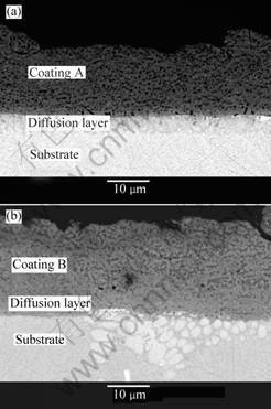
Fig.1 Back- scattered electron (BSE) images of cross-section of coating A (a) and coating B (b)
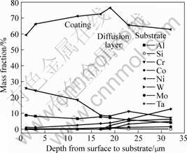
Fig.2 Concentration changes of elements with depth from surface to substrate for coating A after vacuum heat treatment
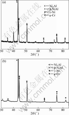
Fig.3 XRD patterns of coating A (a) and coating B (b)
after oxidation, the black oxide (micro-zone “B”) can be verified as Al2O3, and the grey particle (micro-zone “D”) and the white blocky phase (micro-zone “A”) are
deduced to be Al2O3 with a considerable amount of Y2O3. Concerned with coating B, the bright blocky phase (marked “C” in Fig.4(b)) is verified as HfO2. Pint et al[10] pointed out that high content of element Hf in a coating might promote the occurrence of internal oxidation. In fact, element Hf is indeed contained in coating B, so it is easy to understand that the HfO2 amount is evidently higher than that in coating A after oxidation.
Although internal oxidation occurs at the interface between the coating and the superalloy substrate, no cracking can be observed at the interface, signifying a good adhesion between the coating and the DS superalloy substrate.
The formation of Al2O3 can be described as follows: β-NiAl+O2→γ′-Ni3Al+Al2O3. Therefore, the NiAl phases in the coating have been almost completely transformed to Ni3Al phases.
3.3 Phase analysis of coating surface after oxidation
As described previously, the XRD results (Fig.5) indicate that the main phase of the oxidized surfaces of the coatings is Al2O3. Additionally, oxides of Cr2O3 and Y2O3 also exist on the oxidized surfaces. For coating A, the X-ray diffraction peak of SiO2 is detectable. The appearance of AlTaO4 on the oxidized surface of coating B further signifies that element Ta has diffused from the superalloy substrate into the coating. After oxidation at 1 150 ℃ for 100 h, the formed alumina-based oxide scale gives a compacted microstructure and remains intact (Fig.6(a)) except several oxidized spots. However, for the bare DS superalloy, after oxidation, only
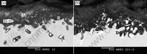
Fig.4 BSE images of cross-section of coating A (a) and the coating B (b)
Table 1 XEDS analysis results of micro-zones marked in Fig.4
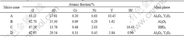
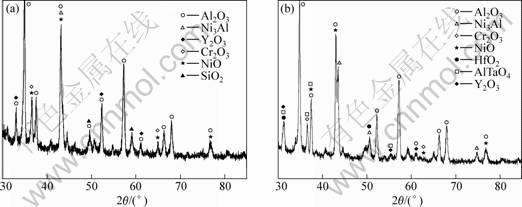
Fig.5 XRD patterns of oxidized surface of coating A (a) and coating B (b)
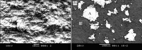
Fig.6 SEM images of surface of coating A (a) and bare alloy (b) after oxidation at 1150 ℃ for 100 h
Table 2 XEDS analysis results of micro-zones marked in Fig.6(b)
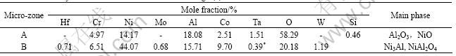
discontinuous alumina-based oxides exist at the oxidized surface (Fig.6(b) and Table 2). According to observation results, oxide spallation occurs during the oxidation. The results of XEDS (Table 2) and XRD (Fig.7) show that the oxidation products of the DS superalloy consist of NiO, Ni(Al,Cr)2O4, AlTaO4 and Al2O3, in which the X-ray diffraction peak of Al2O3 is very weak.
3.4 Oxidation kinetics
The change of total mass gain of the coatings with oxidation time is plotted in Fig.8(a). The experimental data for the bare DS superalloy are also included in Fig.8(a) for comparison. In the initial oxidation stage, the continuous alumina-based oxide scale is not formed, but elements Ni and Cr participate in the oxidation reactions, resulting in the formation of NiO and Cr2O3. Such oxides can not offer an effective protection for the substrate, so the surface shows a high oxidation rate. After 25-50 h, the oxidation behavior comes to a stable stage. This is in accordance with the formation of a continuous alumina-based oxide scale at the outer surface. In fact, the oxidation tendency obeys the parabolic law. The parabolic oxidation rate constant, Kp, can be calculated from the curve fitting of Fig.8(b). Kp decreases from 12.18 g2/(m4?h) for the bare superalloy to 4.40 g2/(m4?h) for coating A and 4.08 g2/(m4?h) for coating B,
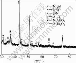
Fig.7 XRD patterns of oxidized surface of bare alloy after oxidation at 1 150 ℃ for 100 h
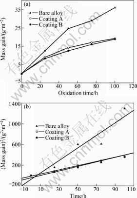
Fig.8 Oxidation kinetics of isothermal oxidation at 1 150 ℃ for 100 h for two coatings and bare alloy: (a) Change of total mass gain with oxidation time; (b) square of total mass gain versus oxidation time for coated specimens and bare alloy
respectively. In other words, Kp of the coated specimens is only 1/3 of that of the bare DS superalloy. Evidently, the oxidation resistance at 1 150 ℃ is improved by the Ni(Co)CrAlY coatings. The oxidation behavior at 1 150 ℃ for longer time will be studied in the next investigation.
4 Conclusions
1) The oxidation kinetics curve of the isothermal oxidation at 1 150 ℃ for 100 h for the Ni(Co)CrAlY coatings fabricated by EB-PVD method obeys the parabolic law, and the oxidation rate constant Kp of the coated specimens decreases from 12 g2/(m4?h) for the bare superalloy to 4.40 g2/(m4?h) (coating A) and 4.08 g2/(m4?h) (coating B), respectively.
2) The two coatings show a good protection at 1 150℃ for the DS superalloy. During high temperature oxidation, the microstructures of the coatings change due to high-temperature diffusion and oxidation reactions. As a result, a continuous alumina-based scale is formed at the surface of the coated samples. A large number of Al is consumed, and the NiAl phases in the coating have almost completely been transformed to Ni3Al phases. Additionally, the thickness of the coatings decrease from 25 μm before oxidation to less than 10 μm after 100 h oxidation at 1 150 ℃.
3) For the bare DS superalloy, after 100 h oxidation at 1 150 ℃, only discontinuous alumina-based oxide particles exist at the surface. Oxide spallation occurs for the bare alloy.
4) The as-received coating contains a deposite layer and a diffusion layer, but after oxidation for 100 h, the diffusion layer disappears, and only an oxide layer mainly composed of alumina is formed at the surface. Y2O3, NiO and SiO2 are also detectable in the oxide layer. For the Hf-bearing coat, some HfO2 particles exist at the interface between the coating and the substrate. Although internal oxidation occurs, the coating still shows a good adhesion with the superalloy substrate.
References
[1] Goulette M J.The future costless―high temperature materials from an aeroengine perspective[C]//Kissinger R D,Deye D J,Anton D L,Cetel A D,Nathal M V,Pollock T M,Woodfond D A. Superalloys 1996. Warrendale: TMS, 1996: 3-6.
[2] Seth B B. The utility gas turbine perspective[C]//Pollock T M, Kissinger R D, Bowman R R, Green K A, McLean M, Olson S, Schirra J J. Superalloys 2000. Warrendale: TMS, 2000: 3-18.
[3] Walston W S. Coating and surface technologies for turbine airfoils[C]//Green K A, Pollock T M, Harada H, Howson T E, Read R C, Schirra J J, Walston S. Superalloys 2004. Warrendale: TMS, 2004: 519-588.
[4] Goward G W. Protective coatings-purpose, role, and design[J]. Materials Science and Technology, 1986, 2(3): 194-200.
[5] Mevrel R, Duret C, Pichoir R. Pack cementation processes[J]. Materials Science and Technology, 1986, 2(3): 201-206.
[6] Mevvel R. State of the art on high-temperature corrosion-resistant coatings[J]. Mater Sci & Eng A, 1989, 120-121(11): 13-24.
[7] Stiger M J, et al. Thermal barrier coatings for the 21st century[J]. Z Metallked, 1999, 90(12): 1069-1078.
[8] Padture N P, Gell M, Jordan E H. Thermal barrier coatings for gas-turbine engine applications[J]. Science, 2002, 296(4): 280-284.
[9] Rabiei A, Evans A G. Failure mechanisms associated with the thermally grown oxide in plasma-sprayed thermal barrier coatings[J]. Acta Mater, 2000, 48(9): 3963-3976.
[10] Pint B A, Haynes J A, More K L, et al. Compsitional effects on aluminide oxidation performance: objectives for improved bond coats[C]//Pollock T M, Kissinger R D, Bowman R R, Green K A, McLean M, Olson S, Schirra J J.Supperalloy 2000. Warrendale: TMS, 2000: 629-638.
(Edited by CHEN Can-hua)
Corresponding author: HUANG Zhao-hui; Tel: +86-10-62496345; E-mail: zhaohui.huang@bian.ac.cn

